US1237199A - Mail-box. - Google Patents
Mail-box. Download PDFInfo
- Publication number
- US1237199A US1237199A US12122916A US12122916A US1237199A US 1237199 A US1237199 A US 1237199A US 12122916 A US12122916 A US 12122916A US 12122916 A US12122916 A US 12122916A US 1237199 A US1237199 A US 1237199A
- Authority
- US
- United States
- Prior art keywords
- box
- receptacle
- auxiliary
- dominant
- Prior art date
- Legal status (The legal status is an assumption and is not a legal conclusion. Google has not performed a legal analysis and makes no representation as to the accuracy of the status listed.)
- Expired - Lifetime
Links
Images
Classifications
-
- A—HUMAN NECESSITIES
- A47—FURNITURE; DOMESTIC ARTICLES OR APPLIANCES; COFFEE MILLS; SPICE MILLS; SUCTION CLEANERS IN GENERAL
- A47G—HOUSEHOLD OR TABLE EQUIPMENT
- A47G29/00—Supports, holders, or containers for household use, not provided for in groups A47G1/00-A47G27/00 or A47G33/00
- A47G29/12—Mail or newspaper receptacles, e.g. letter-boxes; Openings in doors or the like for delivering mail or newspapers
- A47G29/1209—Rural letter-boxes
Definitions
- This invention relates to an imp rofved mailbox, and oneof the objects of'the 'inventio'n is to" providea'device of this nature,
- Another object of the invention isfto improve and simplify and render more pract1- cal the construction of mail box set forth,
- One of the featuresof the invention is to provide arack'and gear connection between a mail box closure and a revolublymou'nted auxiliary mail receptacle, in combination with retaining means for holding the rack and gear connection in cooperation, wherebyth'e closure or'lid, when raised, will' i'otate the auxiliary mail receptacle so that its opening may register with an opening of the first mail box, for the reception of mail matter.
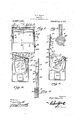
- Figure 1 is a vertical sectional view through the improved mail box constructed in accordance with the invention.
- Fig. 2 is a sectional view on line 2 2 of Fig. 1. a
- Fig. 3 is a sectional view, showing the revolubly mounted auxiliary'mail box in end elevation.
- Fig. 4 is an enlarged detail sectional view on line 4.4 of Fig. 8.
- Fig. 5 is a detail sectional view of the rack retaining roller and its holder, and showing the wheels 11 and 21 in elevation.
- 1 designates the main or dominant mail box, which may be any suitable shape or configuration, and which is provided with a "has I end as ,rthralgh sha the-mail 1 forthepostmanpassft" .e-
- plates 18 may be adjusted slightly. These plates are provided with semi-circular forks 20, which arch over the rollers 21, which are grooved, and are designedto engage the racks 16 to hold their teeth in mesh with the s ecification 6f IaettersfPate iit. WP-atented "14; 19.17.
- - ranged intheddininantjniail box isa partial i" H1: w CYlll'ldFlCttl auxillary mail box 7, having an casing "any-In marunscrew 1'10 ale-"êtteeth of the segmental gears.
- the semi-circular forks or fingers 20 engage the grooves of the rollers or wheels 21 as shown.
- plates 18 with their fingers constitute retaining members for the rollers or wheels 21, whereas the plates and their fingers or forks combined with the rollers or. wheels constitute containing means, to hold the racks in engagement with the segmental gears.
- the auxiliary mail box will be returned, withits opening 8 facing downwardly, and as the auxiliary box is being returned, the flat face 9 acts as a chute, so as to cause the mail to fall directly toward the bottom of the dominant box.
- the flat portion or face 9 also acts as a chute when inserting the mail matter,that is, when the opening 8 is registering with said plates 24.
- One end of thedominant mail box at its lower portion is provided with a hinged closure 27, which may be opened for the extraction of the mail matter in the bottom of the dominant box. However, this closure 27 may be held locked by the suitable padlock 28.
- auxiliary mailbox 7 On the interior of the auxiliary mailbox 7 an angular frame or angular sides 7 and 7 b are provided, which combined with the flat surface or side 9 form the auxiliary mail box or receptacle rectangular on its interior, which renders it easier and more convenient when removing the mail, when such is required, or allows the mail to more easily deposit into the lower part of the main casing or mail box 1. For instance, such construction prevents the mail from binding against the cylindrical side of the auxiliary mail receptacle.
- the under face of the closure or lid 2 is provided with'a pair of ears 2, between which upon Copies of this patent ma be obtained for a pivot pin 2 a coin box 2 is pivoted, which coin box is designed to close against the under face of the lid, there being asuitable coil spring 2 acting to hold the coin box against the under face of the lid, as shown clearly in Figs. 2 and 3 of the drawings.
- a mail box comprising a dominant mail receptacle, a partly revoluble auxiliary mail receptacle mounted-in the upper end of the dominant receptacle and having segmental gears upon its opposite ends, said auxiliary mail receptacle having a rectangular interior contour,the dominant receptacle having a hinged closure provided with racks pivotally connected to the under or inner face of the closure and meshing with the gears, and means upon the inner faces of the ends of the dominant receptacle to retain said racks in.
- said means comprising slotted plates adjustably secured upon the inner faces of the ends of the domi nant receptacle, each plate having semi.-cir cular arched parts, and grooved rollers en gaging between the racks and said arched parts to retain the racks in mesh with the gears.
Description
H. u. GRAVES,.
I MAIL BOX. APPLICATION-FILED SEPT. 20, me.
Patentd Aug. 14, 1917-,
' HENRY D. GRAVES, or Gasm-mnarmmm IVDAIL=130Xi To-aZZ whom it'may'concem." v g 1 Be it-known that I, HENRY GRAVES, a
citizen Orin; United States, residing at Grant Park, in the countyfof Kankak'e'e,
State of Illinois, have invented a new and useful Mail-Box, andI do hereby declare the following to be a full, clear, and exact description of the invention, such as will enable others skilled in the art to which it appertains to makev and use the same.
This invention relates to an imp rofved mailbox, and oneof the objects of'the 'inventio'n is to" providea'device of this nature,
which practical detail features of con struction are involved. Another object of the invention isfto improve and simplify and render more pract1- cal the construction of mail box set forth,
shown and claimed in the patent Henry D. D. Graves, issued Sept. 28, 1915, Patent No. 1,155,146. r r I H One of the featuresof the invention is to provide arack'and gear connection between a mail box closure and a revolublymou'nted auxiliary mail receptacle, in combination with retaining means for holding the rack and gear connection in cooperation, wherebyth'e closure or'lid, when raised, will' i'otate the auxiliary mail receptacle so that its opening may register with an opening of the first mail box, for the reception of mail matter.
In practical fields the details of construction may necessitate alterations, falling within the scope of what is claimed.
The invention comprises further features" and combination of parts, as hereinafter set forth, shown in the drawings and claimed.
In the drawings:
Figure 1 is a vertical sectional view through the improved mail box constructed in accordance with the invention.
Fig. 2 is a sectional view on line 2 2 of Fig. 1. a
Fig. 3 is a sectional view, showing the revolubly mounted auxiliary'mail box in end elevation.
Fig. 4 is an enlarged detail sectional view on line 4.4 of Fig. 8.
Fig. 5 is a detail sectional view of the rack retaining roller and its holder, and showing the wheels 11 and 21 in elevation.
Referring more especially to the drawings, 1 designates the main or dominant mail box, which may be any suitable shape or configuration, and which is provided with a "has I end as ,rthralgh sha the-mail 1 forthepostmanpassft" .e-
nd e ending-pee the iii g i' a 1 ref'talh the mall matterin the receptacle. Ar-
area-e5 eynaantnwan er I 7. S'ecuredaxiallytdfthe a pears near the mental gears 11 "having anal-1y a'r'r an gedpinties 1-2, which are mounted in Bearings 13 "of t ep p asnends rthsabmiaa t' mail bo 1;} r the"app eman tes t e 1161 at 10:
14, an anarchist 'rsthe shag rina rare I k r r and downwardly rom he? cover of closure, and areinmeshwithf'fthe segmntallge'ars 11. s nse t 't aiip' i't l' d' or; we. 'nan't mail box "an-a upon" the "inner'fa'ces' of said ,ends, by means o f screws 17 are plates w nch "provide-swat" slate is). The, screws 17 pass'through the slots 19, so that by loosening and tightening the screws, the
- ranged intheddininantjniail box isa partial i" H1: w CYlll'ldFlCttl auxillary mail box 7, having an casing "any-In marunscrew 1'10 ale-"siegteeth of the segmental gears. The semi-circular forks or fingers 20 engage the grooves of the rollers or wheels 21 as shown. The
will be observed, thatwhen raising the 010- sure or lid, the racks will operate the segoarried bythe opposite ends of the auxiliary mail box, the said box will be partially r0- tated, until the opposite edge 22 of the openmental gears, and owing to the gears being ing 8 will register with the edges 23 of the plates 24, which are secured to the inner faces of the front and rear walls of the dominant mail box. I These plates 24, and also the plate 25 constitute means, to prevent an instrument of any kind from being inserted, between the walls of the dominant and auxiliary mail boxes, for fraudulently removing the mail matter from the bottom of the dominant mail box. It is to be noted that when the closure or lid 2 is thrown to the position in Fig. 2, the auxiliary mail box will be returned, withits opening 8 facing downwardly, and as the auxiliary box is being returned, the flat face 9 acts as a chute, so as to cause the mail to fall directly toward the bottom of the dominant box. The flat portion or face 9, also acts as a chute when inserting the mail matter,that is, when the opening 8 is registering with said plates 24. One end of thedominant mail box at its lower portion is provided with a hinged closure 27, which may be opened for the extraction of the mail matter in the bottom of the dominant box. However, this closure 27 may be held locked by the suitable padlock 28. On the interior of the auxiliary mailbox 7 an angular frame or angular sides 7 and 7 b are provided, which combined with the flat surface or side 9 form the auxiliary mail box or receptacle rectangular on its interior, which renders it easier and more convenient when removing the mail, when such is required, or allows the mail to more easily deposit into the lower part of the main casing or mail box 1. For instance, such construction prevents the mail from binding against the cylindrical side of the auxiliary mail receptacle. The under face of the closure or lid 2 is provided with'a pair of ears 2, between which upon Copies of this patent ma be obtained for a pivot pin 2 a coin box 2 is pivoted, which coin box is designed to close against the under face of the lid, there being asuitable coil spring 2 acting to hold the coin box against the under face of the lid, as shown clearly in Figs. 2 and 3 of the drawings.
The invention having been set forth, what is claimed as new and useful is:
A mail box comprising a dominant mail receptacle, a partly revoluble auxiliary mail receptacle mounted-in the upper end of the dominant receptacle and having segmental gears upon its opposite ends, said auxiliary mail receptacle having a rectangular interior contour,the dominant receptacle having a hinged closure provided with racks pivotally connected to the under or inner face of the closure and meshing with the gears, and means upon the inner faces of the ends of the dominant receptacle to retain said racks in. mesh with the gears, said means comprising slotted plates adjustably secured upon the inner faces of the ends of the domi nant receptacle, each plate having semi.-cir cular arched parts, and grooved rollers en gaging between the racks and said arched parts to retain the racks in mesh with the gears.
In testimony whereof I have signed my name to this specification in the presence of two subscribing witnesses.
' HENRY D. GRAVES.
Witnesses:
MARY MoEoKER, I CHARLES RAYI-IORN.
five cents each, by addressing the Commissioner of Patents, Washington, .D. C.
Priority Applications (1)
| Application Number | Priority Date | Filing Date | Title |
|---|---|---|---|
| US12122916A US1237199A (en) | 1916-09-20 | 1916-09-20 | Mail-box. |
Applications Claiming Priority (1)
| Application Number | Priority Date | Filing Date | Title |
|---|---|---|---|
| US12122916A US1237199A (en) | 1916-09-20 | 1916-09-20 | Mail-box. |
Publications (1)
| Publication Number | Publication Date |
|---|---|
| US1237199A true US1237199A (en) | 1917-08-14 |
Family
ID=3305017
Family Applications (1)
| Application Number | Title | Priority Date | Filing Date |
|---|---|---|---|
| US12122916A Expired - Lifetime US1237199A (en) | 1916-09-20 | 1916-09-20 | Mail-box. |
Country Status (1)
| Country | Link |
|---|---|
| US (1) | US1237199A (en) |
Cited By (3)
| Publication number | Priority date | Publication date | Assignee | Title |
|---|---|---|---|---|
| US20090314828A1 (en) * | 2008-03-20 | 2009-12-24 | Hjorth Consultant, Inc. | Security receptacle |
| US10251503B1 (en) * | 2017-08-14 | 2019-04-09 | Michael Fulps | Secure delivery/drop box for parcels and products |
| US11206940B2 (en) * | 2019-01-24 | 2021-12-28 | Darryl Reed Kaechele | Secure container for receiving and preventing unauthorized access to articles |
-
1916
- 1916-09-20 US US12122916A patent/US1237199A/en not_active Expired - Lifetime
Cited By (4)
| Publication number | Priority date | Publication date | Assignee | Title |
|---|---|---|---|---|
| US20090314828A1 (en) * | 2008-03-20 | 2009-12-24 | Hjorth Consultant, Inc. | Security receptacle |
| US8020752B2 (en) * | 2008-03-20 | 2011-09-20 | Hjorth Consultant, Inc. | Security receptacle |
| US10251503B1 (en) * | 2017-08-14 | 2019-04-09 | Michael Fulps | Secure delivery/drop box for parcels and products |
| US11206940B2 (en) * | 2019-01-24 | 2021-12-28 | Darryl Reed Kaechele | Secure container for receiving and preventing unauthorized access to articles |
Similar Documents
| Publication | Publication Date | Title |
|---|---|---|
| US1237199A (en) | Mail-box. | |
| US1238899A (en) | Book-holder. | |
| US2604260A (en) | Mailbox | |
| US1139491A (en) | Mail-box. | |
| US1030376A (en) | Record-holding cabinet. | |
| US1514146A (en) | Deposit and collection receptacle | |
| US464275A (en) | Street letter-box | |
| US1197576A (en) | Display-rack. | |
| US1250998A (en) | Mail-box. | |
| US1155146A (en) | Mail-box. | |
| US3847457A (en) | Tamper proof storage and dispensing unit for cans of oil and the like | |
| US550502A (en) | Thirds to arthur j | |
| US483525A (en) | Island | |
| US1306795A (en) | Ticket-cabinet | |
| CH566747A5 (en) | Small box for storage and filing of photographic slides - has rectangular compartment with shelves inclining as saw teeth relative to one another | |
| US1450772A (en) | Milk-bottle receptacle | |
| US1010519A (en) | Mail-box. | |
| US1194950A (en) | Best available copt | |
| US1161564A (en) | Dispensing-cabinet. | |
| US1190758A (en) | Sheet-receiving cabinet. | |
| US977660A (en) | Milk-can. | |
| US1698409A (en) | Telephone cabinet | |
| US1305865A (en) | Milk-bottle beceptacle | |
| US929369A (en) | Mail-box. | |
| US1028705A (en) | Garbage-can holder. |