US1237185A - Tool-holder. - Google Patents
Tool-holder. Download PDFInfo
- Publication number
- US1237185A US1237185A US13984716A US13984716A US1237185A US 1237185 A US1237185 A US 1237185A US 13984716 A US13984716 A US 13984716A US 13984716 A US13984716 A US 13984716A US 1237185 A US1237185 A US 1237185A
- Authority
- US
- United States
- Prior art keywords
- tool
- bar
- rest
- opening
- section
- Prior art date
- Legal status (The legal status is an assumption and is not a legal conclusion. Google has not performed a legal analysis and makes no representation as to the accuracy of the status listed.)
- Expired - Lifetime
Links
Images
Classifications
-
- B—PERFORMING OPERATIONS; TRANSPORTING
- B23—MACHINE TOOLS; METAL-WORKING NOT OTHERWISE PROVIDED FOR
- B23B—TURNING; BORING
- B23B29/00—Holders for non-rotary cutting tools; Boring bars or boring heads; Accessories for tool holders
- B23B29/03—Boring heads
- B23B29/034—Boring heads with tools moving radially, e.g. for making chamfers or undercuttings
- B23B29/03403—Boring heads with tools moving radially, e.g. for making chamfers or undercuttings radially adjustable before starting manufacturing
- B23B29/03407—Boring heads with tools moving radially, e.g. for making chamfers or undercuttings radially adjustable before starting manufacturing by means of screws and nuts
-
- Y—GENERAL TAGGING OF NEW TECHNOLOGICAL DEVELOPMENTS; GENERAL TAGGING OF CROSS-SECTIONAL TECHNOLOGIES SPANNING OVER SEVERAL SECTIONS OF THE IPC; TECHNICAL SUBJECTS COVERED BY FORMER USPC CROSS-REFERENCE ART COLLECTIONS [XRACs] AND DIGESTS
- Y10—TECHNICAL SUBJECTS COVERED BY FORMER USPC
- Y10T—TECHNICAL SUBJECTS COVERED BY FORMER US CLASSIFICATION
- Y10T408/00—Cutting by use of rotating axially moving tool
- Y10T408/57—Tool-support with means to receive tool-position indicator
-
- Y—GENERAL TAGGING OF NEW TECHNOLOGICAL DEVELOPMENTS; GENERAL TAGGING OF CROSS-SECTIONAL TECHNOLOGIES SPANNING OVER SEVERAL SECTIONS OF THE IPC; TECHNICAL SUBJECTS COVERED BY FORMER USPC CROSS-REFERENCE ART COLLECTIONS [XRACs] AND DIGESTS
- Y10—TECHNICAL SUBJECTS COVERED BY FORMER USPC
- Y10T—TECHNICAL SUBJECTS COVERED BY FORMER US CLASSIFICATION
- Y10T408/00—Cutting by use of rotating axially moving tool
- Y10T408/83—Tool-support with means to move Tool relative to tool-support
- Y10T408/85—Tool-support with means to move Tool relative to tool-support to move radially
- Y10T408/858—Moving means including wedge, screw or cam
- Y10T408/8598—Screw extending perpendicular to tool-axis
Definitions
- Ki ali/a To all whomit may concern:
- boring bars such as used in upright 01' hori-' zontal boring machines.
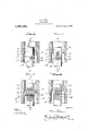
- Figure 1 is an elevation illustrating a boring bar constructed in accordance with my invention as the same appears when in use.
- Fig. 2 is a side elevation of the boring bar, with the cutting tool in section, taken at a right angle to Fig. 1, the section being on line 22 of Fig. 1.
- Fig. 3 is a detail diametrical section, taken through and showing the relative arrangement of the tool support and feeding device, the bar, and the screw through the medium of which said support and feeding device is adjusted and adjustably fixed, the section being on line 3-3 of Fig. 2.
- Fig. 4 is a section on line 4 4: of Fig. 3.
- Fig. 1 in Fig. 1 indicates an opening in which my improved device is illustrated at work.
- the bar 2 of the improved device is provided at 3 with a diametrically-disposed opening, and in communication with the lower portion of the said opening 3 and extending in the same direction as the same is a smooth groove 4, of semi-circular form in cross-section.
- a graduated scale 5 is preferably, though not necessarily, provided as illustrated.
- a cutting tool 6 Arranged in the opening 3 and extending diametrically of the bar 2 is a cutting tool 6, and also arranged in the lower portion of the opening is the tool rest and feeder 7. It will be noticed here that the lower portion of the opening 3 is of dovetail form in crosssection as is also the tool rest and feeder 7. This, however, is merely a preferred form,
- the support and feeder 7 and the opening portion 'in whichit is disposed may be of any other desired form in cross section without aifecting my invention.
- the tool rest and feeder is'provided with a flange 8 which abuts against the rear end of the tool, and at its opposite side, with reference'to the tool, the rest and feeder is provided with a threaded'groove 9, ofsemicircular form in cross-sectiomrThis roove9 is opposed to the groove 1in the ar 2, and the two are" adapted to receive the screw 10 which has for its function to adjustand' a djustably fix the rest 7 and the tool 6 so as to properly holdthe latter to its work.
- the said screw 10 has an angular protuberance 11 at its outer end or is otherwise adapted for the en-v gagement of a-turning device, and it is provided with a pointer 12, designed to cooperate with the before described scale 5.
- the said pointer 12 and scale 5 are employed in order to enable the operator to see the extent to which the cutting tool is adjusted, but it is obvious that they may be omitted in the discretion of the manufacturer-of my improved device, without departure from the scope of my claims.
- the cutting tool is held to its work and against retrograde movement by the rest 7, which in turn, is held by the screw 10 bearing in the bar 2. It will be manifest that the flange 8 on the rest 7 will preclude backward movement of the tool when a hard spot in the work is encountered; also, that by virtue of the screw connection intermediate the rest 7 and the bar 2, the tool may be quickly and accurately advanced to compensate for wear or may otherwise be adjusted and adjustably fixed.
- the tool advances into the work in the direction indicated by arrow in Fig. 1, and hence it will be observed that the screw 10 may be turned about its axis to attain the adjustment desired without the necessity of removing the bar 2 from the work.
- a tool-holding construction the combination of a bar having a diametrically disposed opening and also having a smooth groove, of semicircular form in cross-section, communicating with and extending in the same direction as said opening, a tool rest and feeder having a flange at its rear end adapted to be opposed to the rear end of a tool and also having a threaded groove of semi-circular form in cross section opposed to the smooth groove in the bar, and a screw interposed between the bar and the tool rest and engaging the threaded portions of the tool rest and adapted to adjust and adjustably fix the latter.
- a bar having a diametricallydisposed opening, and a groove, of semi-circular form in cross-section, communicating with and extending in the same direction as said opening and also having a graduated scale adjacent to the outer end of said groove;
- a tool rest and feeder having a flange at its rear end adapted tobe opposed to the rear end of a tool and also having a threaded groovevof semi-circular form in cross-section opposed to the groove in the bar, and a screw interposed between and engaging the threaded portion of the tool rest and feeder and having a pointer adapted to cooperate with the scale of the bar.
Description
A. L. EWE N.
TOOL HOLDER.
APPLICATION FILED oEc.ao.-191s.
Patented Aug. 14, 1917.
g L i 4 m h W AF II. w
Ki ali/a To all whomit may concern:
Be it known that I, ADAM L. EWEN, a citizen of the United States, residing at North Smithfield, in the county of Providence and State of Rho'de Island, have invented new and useful Improvements in Tool-Holders, of which the following is a.
boring bars such as used in upright 01' hori-' zontal boring machines.
In the accompanying drawings, which are hereby made a part hereof.
Figure 1 is an elevation illustrating a boring bar constructed in accordance with my invention as the same appears when in use.
Fig. 2 is a side elevation of the boring bar, with the cutting tool in section, taken at a right angle to Fig. 1, the section being on line 22 of Fig. 1.
Fig. 3 is a detail diametrical section, taken through and showing the relative arrangement of the tool support and feeding device, the bar, and the screw through the medium of which said support and feeding device is adjusted and adjustably fixed, the section being on line 3-3 of Fig. 2.
Fig. 4 is a section on line 4 4: of Fig. 3.
Similar numerals of reference designate corresponding parts in all of the views of the drawings.
1 in Fig. 1 indicates an opening in which my improved device is illustrated at work.
The bar 2 of the improved device is provided at 3 with a diametrically-disposed opening, and in communication with the lower portion of the said opening 3 and extending in the same direction as the same is a smooth groove 4, of semi-circular form in cross-section. On the face of the bar and adjacent to the outer end of the said smooth groove a graduated scale 5 is preferably, though not necessarily, provided as illustrated.
Arranged in the opening 3 and extending diametrically of the bar 2 is a cutting tool 6, and also arranged in the lower portion of the opening is the tool rest and feeder 7. It will be noticed here that the lower portion of the opening 3 is of dovetail form in crosssection as is also the tool rest and feeder 7. This, however, is merely a preferred form,
Specification of Letters Patent.
,. ran srarrns rA'rnNT OFFICE,
ADAM L. EwEmor NORTH SMITHFIELD, nnonr. ISLAND.
Patented Aug. 14, 1917.
Application filed December 30, 1916. serial No. 139,847.
and I would have it understoodthat the support and feeder 7 and the opening portion 'in whichit is disposed may be of any other desired form in cross section without aifecting my invention. :At itsrear end the tool rest and feeder is'provided with a flange 8 which abuts against the rear end of the tool, and at its opposite side, with reference'to the tool, the rest and feeder is provided with a threaded'groove 9, ofsemicircular form in cross-sectiomrThis roove9 is opposed to the groove 1in the ar 2, and the two are" adapted to receive the screw 10 which has for its function to adjustand' a djustably fix the rest 7 and the tool 6 so as to properly holdthe latter to its work. The said screw 10 has an angular protuberance 11 at its outer end or is otherwise adapted for the en-v gagement of a-turning device, and it is provided with a pointer 12, designed to cooperate with the before described scale 5. The said pointer 12 and scale 5 are employed in order to enable the operator to see the extent to which the cutting tool is adjusted, but it is obvious that they may be omitted in the discretion of the manufacturer-of my improved device, without departure from the scope of my claims.
In the practical use of my novel construction, the cutting tool is held to its work and against retrograde movement by the rest 7, which in turn, is held by the screw 10 bearing in the bar 2. It will be manifest that the flange 8 on the rest 7 will preclude backward movement of the tool when a hard spot in the work is encountered; also, that by virtue of the screw connection intermediate the rest 7 and the bar 2, the tool may be quickly and accurately advanced to compensate for wear or may otherwise be adjusted and adjustably fixed.
The tool advances into the work in the direction indicated by arrow in Fig. 1, and hence it will be observed that the screw 10 may be turned about its axis to attain the adjustment desired without the necessity of removing the bar 2 from the work.
I would further have it understood that my improvements are susceptible of being arranged in the bar 2 at any point intermediate the ends of the said bar, as the character of different pieces of work requires.
It will be noted that incidental to the use of the holder the screw 10 will operate against the vertical wall of the groove and inthe threaded part of the rest 7.
Having described my invention, what I claim and desire to secure by Letters Patent, is:
1. In a tool-holding construction, the combination of a bar having a diametrically disposed opening and also having a smooth groove, of semicircular form in cross-section, communicating with and extending in the same direction as said opening, a tool rest and feeder having a flange at its rear end adapted to be opposed to the rear end of a tool and also having a threaded groove of semi-circular form in cross section opposed to the smooth groove in the bar, and a screw interposed between the bar and the tool rest and engaging the threaded portions of the tool rest and adapted to adjust and adjustably fix the latter.
2. In a tool-holding construction, the combination of a bar having a diametricallydisposed opening, and a groove, of semi-circular form in cross-section, communicating with and extending in the same direction as said opening and also having a graduated scale adjacent to the outer end of said groove; a tool rest and feeder having a flange at its rear end adapted tobe opposed to the rear end of a tool and also having a threaded groovevof semi-circular form in cross-section opposed to the groove in the bar, and a screw interposed between and engaging the threaded portion of the tool rest and feeder and having a pointer adapted to cooperate with the scale of the bar.
Intestimony whereof I have hereunto. set
my hand in presence of two subscribing witnesses.
ADAM L. EWEN.
Witnesses: i
EDGAR L. SPAULDING, EVELYN W. SPAULDING.
Gopies of this patent may be obtained for five cents each, by addressing the Commissioner of Patents,
Washington, D. C.
Priority Applications (1)
| Application Number | Priority Date | Filing Date | Title |
|---|---|---|---|
| US13984716A US1237185A (en) | 1916-12-30 | 1916-12-30 | Tool-holder. |
Applications Claiming Priority (1)
| Application Number | Priority Date | Filing Date | Title |
|---|---|---|---|
| US13984716A US1237185A (en) | 1916-12-30 | 1916-12-30 | Tool-holder. |
Publications (1)
| Publication Number | Publication Date |
|---|---|
| US1237185A true US1237185A (en) | 1917-08-14 |
Family
ID=3305003
Family Applications (1)
| Application Number | Title | Priority Date | Filing Date |
|---|---|---|---|
| US13984716A Expired - Lifetime US1237185A (en) | 1916-12-30 | 1916-12-30 | Tool-holder. |
Country Status (1)
| Country | Link |
|---|---|
| US (1) | US1237185A (en) |
Cited By (2)
| Publication number | Priority date | Publication date | Assignee | Title |
|---|---|---|---|---|
| US4163624A (en) * | 1977-02-09 | 1979-08-07 | Komet Stahlhalter- Und Werkzeugfabrik Robert Breuning Gmbh | Toolholder for recessing operations, in particular a boring bar |
| US20190270614A1 (en) * | 2018-03-02 | 2019-09-05 | Otis Elevator Company | Rope cleaning device |
-
1916
- 1916-12-30 US US13984716A patent/US1237185A/en not_active Expired - Lifetime
Cited By (2)
| Publication number | Priority date | Publication date | Assignee | Title |
|---|---|---|---|---|
| US4163624A (en) * | 1977-02-09 | 1979-08-07 | Komet Stahlhalter- Und Werkzeugfabrik Robert Breuning Gmbh | Toolholder for recessing operations, in particular a boring bar |
| US20190270614A1 (en) * | 2018-03-02 | 2019-09-05 | Otis Elevator Company | Rope cleaning device |
Similar Documents
| Publication | Publication Date | Title |
|---|---|---|
| US1237185A (en) | Tool-holder. | |
| US908804A (en) | Tool-holder. | |
| US85329A (en) | Charles h | |
| US407972A (en) | Tool holder and rest for lathes | |
| US859336A (en) | Double-acting tool for planers and shapers. | |
| US1017112A (en) | Tool-holder. | |
| US228429A (en) | Device for cutting screw-threads | |
| US10744A (en) | Drill foe | |
| US228882A (en) | Screw-tap | |
| US1233174A (en) | Adjustable holder for boring-tools. | |
| US1118141A (en) | Boring-bar. | |
| US537049A (en) | Surgical pump | |
| US680775A (en) | Lathe-dog. | |
| US775672A (en) | Tap or thread-cutter. | |
| US332833A (en) | Metal-turning lathe | |
| US333937A (en) | Tapping-machine | |
| US641380A (en) | Automatic machine-chuck. | |
| US853394A (en) | Bur-wheel support for knitting-machines. | |
| US1067260A (en) | Actuating mechanism for lathes. | |
| US593066A (en) | Said sweetser and said george ii | |
| US1315640A (en) | Tool-holder | |
| US598196A (en) | Attachment for screw-threading machines | |
| US589110A (en) | Drilling apparatus | |
| US143242A (en) | Improvement in gear-cutting attachments to lathes | |
| US398575A (en) | Paper-cutter |