US1237131A - Method of manufacturing reinforced inner tubes of pneumatic tires and mandrels therefor. - Google Patents
Method of manufacturing reinforced inner tubes of pneumatic tires and mandrels therefor. Download PDFInfo
- Publication number
- US1237131A US1237131A US14866117A US14866117A US1237131A US 1237131 A US1237131 A US 1237131A US 14866117 A US14866117 A US 14866117A US 14866117 A US14866117 A US 14866117A US 1237131 A US1237131 A US 1237131A
- Authority
- US
- United States
- Prior art keywords
- tube
- mandrel
- rubber
- fabric
- mandrels
- Prior art date
- Legal status (The legal status is an assumption and is not a legal conclusion. Google has not performed a legal analysis and makes no representation as to the accuracy of the status listed.)
- Expired - Lifetime
Links
Images
Classifications
-
- B—PERFORMING OPERATIONS; TRANSPORTING
- B29—WORKING OF PLASTICS; WORKING OF SUBSTANCES IN A PLASTIC STATE IN GENERAL
- B29D—PRODUCING PARTICULAR ARTICLES FROM PLASTICS OR FROM SUBSTANCES IN A PLASTIC STATE
- B29D23/00—Producing tubular articles
- B29D23/24—Endless tubes, e.g. inner tubes for pneumatic tyres
-
- B—PERFORMING OPERATIONS; TRANSPORTING
- B29—WORKING OF PLASTICS; WORKING OF SUBSTANCES IN A PLASTIC STATE IN GENERAL
- B29C—SHAPING OR JOINING OF PLASTICS; SHAPING OF MATERIAL IN A PLASTIC STATE, NOT OTHERWISE PROVIDED FOR; AFTER-TREATMENT OF THE SHAPED PRODUCTS, e.g. REPAIRING
- B29C41/00—Shaping by coating a mould, core or other substrate, i.e. by depositing material and stripping-off the shaped article; Apparatus therefor
- B29C41/24—Shaping by coating a mould, core or other substrate, i.e. by depositing material and stripping-off the shaped article; Apparatus therefor for making articles of indefinite length
-
- B—PERFORMING OPERATIONS; TRANSPORTING
- B29—WORKING OF PLASTICS; WORKING OF SUBSTANCES IN A PLASTIC STATE IN GENERAL
- B29K—INDEXING SCHEME ASSOCIATED WITH SUBCLASSES B29B, B29C OR B29D, RELATING TO MOULDING MATERIALS OR TO MATERIALS FOR MOULDS, REINFORCEMENTS, FILLERS OR PREFORMED PARTS, e.g. INSERTS
- B29K2021/00—Use of unspecified rubbers as moulding material
-
- Y—GENERAL TAGGING OF NEW TECHNOLOGICAL DEVELOPMENTS; GENERAL TAGGING OF CROSS-SECTIONAL TECHNOLOGIES SPANNING OVER SEVERAL SECTIONS OF THE IPC; TECHNICAL SUBJECTS COVERED BY FORMER USPC CROSS-REFERENCE ART COLLECTIONS [XRACs] AND DIGESTS
- Y10—TECHNICAL SUBJECTS COVERED BY FORMER USPC
- Y10T—TECHNICAL SUBJECTS COVERED BY FORMER US CLASSIFICATION
- Y10T152/00—Resilient tires and wheels
- Y10T152/10—Tires, resilient
- Y10T152/10495—Pneumatic tire or inner tube
- Y10T152/10666—Automatic sealing of punctures [e.g., self-healing, etc.]
- Y10T152/10675—Using flowable coating or composition
- Y10T152/10702—Using flowable coating or composition within or part of construction of inflating inner tube
- Y10T152/10711—Sealant in plural layers or plural pockets
Definitions
- nouns e. WELGH, or rnInaim rmA ramsrztvame.
- the invention relates to tubes andv tires
- the invention comprehends an inner pneumatic tube for tires,-which is parts, in the, making of the tube, so arranged and related that in the finished article there will presented a nitary structure or homogeneous construction in which the very adaptation of the structures and compositions used to form the artiele, and the less operations ineulfm'd, in the assembling andconnection of the valve mechanism with cat on in whichsimilar charactersbfiefer method employed in the formation, will 'brin X about" a construction resisting the .usua wear, and affording self-mendinger healing h ualities, the usual val"e mechanism emp oyedjbeing also so related to the i a tube proper. that the tendencof weakness at. the joint-or connection oft e alve mechanism with the tube, will be,-overcome,fand
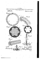
- a Fig. 4 is a sectional view takenthrough the tube removed from the mandrel, the dotted lines indicating the appearance when inflated.
- Fig. 5 is a fragmentary perspective view showing a portion of the straight mandrel.
- Fig. 6 is a fragmentary sectional view taken through the in drel and the valve to be employedwith't e tube, showing the manner of holding the valve in position upon the mandrel while the tube is being formed
- T Fig. 7 is a fragmentary sectional V1eW' taken through the valve showing the same in position on the tube, after the same has been removed from the mandrel.
- I provide a mandrellO' of an annular or circumferential shape, and having a removable section 11 which can be ciated with the body of the mandrel to form a continuous constructiomthe section being provided for the purpose of facilitating the removal of the finished tube, after the same -has been formed upon the mandrel.
- the mandrel is formed with longitudinal or circumferentially arranged channels or grooves 12, so that the entire periphcry of themandrel is of corrugated effect, the formation of the grooves naturally pro viding longitudinal clrcumferential ribs 13 grooves or channels, and to Figs. 2 and 3 it will be noted.
- FIG. 5 there is disclosed a straight mandrel 10 having grooves or channels 12, and of course ribs 13 similar to the ribs 13, the
- a layer of fabric 14 is wrapped around the mandrel and ispressed into the grooves or channels 12, the layer of fabric I tothe shape thereof in every particular, wit the fabric following the periphery of the mandrelin the grooves or channels and coverlng the IlbS 13. It will of course-be under- .stood that in a similar mannerthe fabric is wrapped around the straight mandrel, .shown in Fig. 5, so that it will conform to thej p'eripheral formation thereof, thusproviding plaits 15, and result in an undusuitably assobe seen that the head integral therewith.
- the-fabric also forming grooves or channels 15 in the grooves or' channels 12.
- plastic rubber composition indicated by the numeral 17
- this plastic rubber is d1sposed to fill up the grooves or channels 16 in the fabric, and also cover the plates 15, so that-the surface of the applied coat orlayer ofplastic rubber composition will be substantially circular in cross section.
- a covering orla er of rubber 18 is then wrapped aroun or applied to the already formed body of the tube, as shown in Fig.
- said layer of rubber being also circular in cross section, and uniformly wrapped around to entirel inclose the plastic rubber composition, s'o t at the plastic rubber composition will lie between the fabric layer and the outer layer or covering of rubber, it being readilyseen that there will be more of the lastic rubber between the groove or channei portions of the fabric and the outer layer of rubber, than between the ribbed portions of the fabric or the plaits 15 and.
- the assembled elements are now subjected to vulcanization in the usual' or any preferred manner, and it will be seen that the same will become a homogeneous or unitary construction, so that when the tube is subsequently removed from the mandrel, either by sliding it off of'the straight mandrel, or by slitting the tube and removing the 'section 11 of the circumferentialmandrel, and then sliding off the tube, the said tube Will consist of an innerfabric construction, and an outer rubber construction, with an interposed plastic rubber formation, or vice versa,'in the event the. tube is reversed to have the fabric layer on the outside and the layer of rubber on the inside.
- the inner .head end 19 of a valve 20 including a tubular stem 21 is arranged in one-of the grooves or channels12 of the mandrel, and'115 a stem or rod 22 is inserted through the tubular portion of the valve stem, and has its one end threaded into a suitable opening 23 in the mandrel, thus holding the valve rigidly in position upon the mandrel.
- the fabric is then applied to the mandrel as described heretofore, and will surround the inner end of the stem, as will also the plastic rubbercomposition and the covering of rubber, and when these parts are subsequently subjected .to vulcanization, it will end'of the valve and the inner end ofthe stem will also become a part of the inner tube, and appear to be rod 22, after the vulcanization process is completed, is removed from the mandrel and the tube can then be slid off with the valve as a component part thereof, thus obviating the necessity of separately attaching, patching and vulcanizing the valve to the tube, as is now usually done, the tube with the valve applied thereto in the manner mentioned and vulcanized into a homogeneous construction, this being followed out with or without the particular valve application disclosed herein.
- the i said interposed layer or portion of live and movable plastic composition also greatly adding to the strength of the completed tube and its cushioning effect when the tube is in use, while at the same time the interposed plastic rubbe'r composition will on account of the vulcaiiizing process, securely bind the fabric and rubber coverings'or layers to each other, whether the rubber layer is on the outside and the fabric on he inside, as shown, or whether the fabric is on the outside and the rubber on the inside, as might be accomplished by simply reversing or turning inside out the completed tube.
- a tube of the character described there is provided a construction of simple formation, embodying a minimum amount of material, and by which there is provided a tube that in use, and when associated with theusual shoe or tire, will be su'l'liciently blow-out proof and of self-healing or mending qualities, due to the provision of the plastic composition rubber.
- the latter is of extreme importance in that the tube, by reason of its formation, will be absolutely pinchproof; that is to say, in the'application of the tube to a tire and the mounting-of the same upon the felly of a wheel, the tube will not be pinched as is ofttimes the case with present tubes now generally used, and
- a tube of the character mentioned will be less liable to be rim-cut than the ordinary tubes now generally used due also to the formation of the tube and the use of the plastic composition rubber, related as it is to the inner and outer coverings set forth herein.
- a mandrel for making tubes comprising an annular body, substantially circular in cross sectionand formed to provide ridges and hollows, said ridges and hollows extending circumferentially of said annular body.
- a mandrel for making tubes comprising acircular body on which the tube is Wrapped, a removable section or sections for said body and normally forming a part thereof, said section or sections permitting the removal of the completed tube, and channels formed in said body and sections and extrinding cireumferentially of said mandre 3.
- a mandrel comprising a body for the formation of the tube thereon, and having one or more channels extending circumfercntially thereof, and means associated with said body for the positioning of the valve in the tube when the tube is formed on the body.
Description
II. G. WELCH. METHOD OF MANIJFACTURING REINFORCED INNER TUBES 0F PNEUMATIC TIRES AND MANDRELS THEREFOR.
APPLICATION FILED FEB. H; 19.
. Patented Augyl i, 1917.
vymuzsszs UNITED STATES. PATENT ()FFIOE.
nouns. e. WELGH, or rnInaim rmA ramsrztvame.
METHOD orgumnrac runme nnmroncnn INNER TUBES or rnnmmn'rrc 'rmns Ann nmmmts :rnnmnroa.
- Be it known that I, HOMER G. WELGH, a citizen of'the United States, residingmt 809 Finance Bldg.,Philadelphia, 'in the county of Philadelphia 'and State of Pennsylvania,
- have invented newand useful Improvements in Methods of Manufacturing Reinforced Inner Tubes 'of Pneumatic Tires and Man- .drels Therefor, of which the following is a specification.
The invention relates to tubes andv tires,
of the confined air; constructed to conformto the character of tires generally used in connection with pneumatietubes and-by virtufeaof its own construction formed to insure -of, simple formatiom and has its component atube oflasting durability" and strength, to withstand rupture after inflation. when subi'le ted to theforces and pressures occasioned r y the for which it'is intended.
Still "further, the invention comprehends an inner pneumatic tube for tires,-which is parts, in the, making of the tube, so arranged and related that in the finished article there will presented a nitary structure or homogeneous construction in which the very adaptation of the structures and compositions used to form the artiele, and the less operations ineulfm'd, in the assembling andconnection of the valve mechanism with cat on in whichsimilar charactersbfiefer method employed in the formation, will 'brin X about" a construction resisting the .usua wear, and affording self-mendinger healing h ualities, the usual val"e mechanism emp oyedjbeing also so related to the i a tube proper. that the tendencof weakness at. the joint-or connection oft e alve mechanism with the tube, will be,-overcome,fand
" the tube.
r I It is well knownthat in'the manufacture of. reinforced inner tubes for pneumatic es, the;re -is employed the usual mandrel finished, Frovide strong and durable tubes,
'structions, will not render its best qualities heal the opening made, and prevent the ir,
wardly therethrough.-
ta es ue" Patent. t t g in I Application fllcd rebruary 14, 1917. Serial No. 148,661.
To alll whom it'may concern:
construction which when subsequentl csub- I ected to vulcanization, will brmga out ie finished article capable of being 3 after removal from the mandrel, and-"which Wlll provlde and form the cushioningeffect. 60 necessary to pneumatic tires. t'lnmthesef;
known constructions, however, the relatives arrangement-of the layers of fabric and box does not of necessity, when the article o devoid 0 weak portions or spots, ands-ems hodying puncture-healing qualities,-nor does 1t provide for a tube that will insure uniform mflatlon, these defects being'not-on'ly due to the manner of making the tube and the maternal employed, or the relativevar rangement of the materials employedybutlto. the peculiar. qualities-of rubber, and-which if not adapted to conform to certaineon T5 to thedes red end, namely, the provision-0f a'tube that can be inflated, and williwith stand the wear and tear, and other peculiar conditions to which tubes for tires are sub-1 I jected. 1 lyith this in mind, I aim to rovide a tube winch is formed on a peculiar y" constructed mandrel, that Ina be eitherstraight or cit cumferential, an which will result intheghspositlon; of fabric, aplastidrubber lik'e 5; composltion, and a covering Orfiditioiial layer of rubber, in which the construction of the mandrel and the formation andsjrrangement of the parts composing the-tube, will result, when the finished. tube"is-s'ubs- 19,0 quently inflated, ina substantially'unifofm distribution of the plastic rubber like-300111 position between the fabric laye i andfthe vlayer of'rubber, so that the insertion of ai' nail or other puncture-producing imple-aigg ment, wlll'cause the plastlc composition to" contained in the. tube from pain tdraw1ngs,"constit' ting a part of thisispee denote corresponding parf ifi. v1ews,' .and 111 who I aneleyation of th fii d new In' thefurth r disclosure of the invention, V reference lsito be'hadto, the aceompanyi g.
through the mandrel showing the manner of forming the tube thereon. a Fig. 4 is a sectional view takenthrough the tube removed from the mandrel, the dotted lines indicating the appearance when inflated. A
Fig. 5 is a fragmentary perspective view showing a portion of the straight mandrel.
Fig. 6 is a fragmentary sectional view taken through the in drel and the valve to be employedwith't e tube, showing the manner of holding the valve in position upon the mandrel while the tube is being formed, and T Fig. 7 is a fragmentary sectional V1eW' taken through the valve showing the same in position on the tube, after the same has been removed from the mandrel.
Referring more particularly to the views, I provide a mandrellO' of an annular or circumferential shape, and having a removable section 11 which can be ciated with the body of the mandrel to form a continuous constructiomthe section being provided for the purpose of facilitating the removal of the finished tube, after the same -has been formed upon the mandrel. Referring carefully to Figs. 2 and 3, it will be seen that the mandrel is formed with longitudinal or circumferentially arranged channels or grooves 12, so that the entire periphcry of themandrel is of corrugated effect, the formation of the grooves naturally pro viding longitudinal clrcumferential ribs 13 grooves or channels, and to Figs. 2 and 3 it will be noted.
between adjacent referring that the entiresurface of the mandrel, as Well as its associated section 11, have the grooves or channels formed therein. In Fig. 5 there is disclosed a straight mandrel 10 having grooves or channels 12, and of course ribs 13 similar to the ribs 13, the
when applied to the mandrel conformin only difference in construction being that the mandrel shown in Figs. l2 and 3 'is annular in shape; whereas, the mandrel shown in Fig. 5 is straight, in thenature of a bar, it being understoodthaf'th e formationof the tubeo'n either of the mandrels 'is substantially the same, except in the removal thereof when the tube is finished.
After'thesection 1.1 has been arranged upon the mandrel 10 in the annular form of mandrel, a layer of fabric 14. is wrapped around the mandrel and ispressed into the grooves or channels 12, the layer of fabric I tothe shape thereof in every particular, wit the fabric following the periphery of the mandrelin the grooves or channels and coverlng the IlbS 13. It will of course-be under- .stood that in a similar mannerthe fabric is wrapped around the straight mandrel, .shown in Fig. 5, so that it will conform to thej p'eripheral formation thereof, thusproviding plaits 15, and result in an undusuitably assobe seen that the head integral therewith. The
lated construction, the-fabric also forming grooves or channels 15 in the grooves or' channels 12.
After the fabric has been wrapped around the mandrel,.the. fabricis covered with a quantity of what might be termed, plastic rubber composition, indicated by the numeral 17, and this plastic rubber is d1sposed to fill up the grooves or channels 16 in the fabric, and also cover the plates 15, so that-the surface of the applied coat orlayer ofplastic rubber composition will be substantially circular in cross section. A covering orla er of rubber 18 is then wrapped aroun or applied to the already formed body of the tube, as shown in Fig. 3, said layer of rubber being also circular in cross section, and uniformly wrapped around to entirel inclose the plastic rubber composition, s'o t at the plastic rubber composition will lie between the fabric layer and the outer layer or covering of rubber, it being readilyseen that there will be more of the lastic rubber between the groove or channei portions of the fabric and the outer layer of rubber, than between the ribbed portions of the fabric or the plaits 15 and.
the outer layer of rubber.
The assembled elements are now subjected to vulcanization in the usual' or any preferred manner, and it will be seen that the same will become a homogeneous or unitary construction, so that when the tube is subsequently removed from the mandrel, either by sliding it off of'the straight mandrel, or by slitting the tube and removing the 'section 11 of the circumferentialmandrel, and then sliding off the tube, the said tube Will consist of an innerfabric construction, and an outer rubber construction, with an interposed plastic rubber formation, or vice versa,'in the event the. tube is reversed to have the fabric layer on the outside and the layer of rubber on the inside.
Prior'to the application of the fabric, the plastic rubber composition and the covering of rubber to the mandrel, however, the inner .head end 19 of a valve 20 including a tubular stem 21, is arranged in one-of the grooves or channels12 of the mandrel, and'115 a stem or rod 22 is inserted through the tubular portion of the valve stem, and has its one end threaded into a suitable opening 23 in the mandrel, thus holding the valve rigidly in position upon the mandrel. The fabric is then applied to the mandrel as described heretofore, and will surround the inner end of the stem, as will also the plastic rubbercomposition and the covering of rubber, and when these parts are subsequently subjected .to vulcanization, it will end'of the valve and the inner end ofthe stem will also become a part of the inner tube, and appear to be rod 22, after the vulcanization process is completed, is removed from the mandrel and the tube can then be slid off with the valve as a component part thereof, thus obviating the necessity of separately attaching, patching and vulcanizing the valve to the tube, as is now usually done, the tube with the valve applied thereto in the manner mentioned and vulcanized into a homogeneous construction, this being followed out with or without the particular valve application disclosed herein. y
Referring to Fig. 4 it will be seen that when'the finished tube is subjected to an air pressure by inflation, the fabric will tend to distend into a uniform circular construction, causing the thickened portions of plastic 'rubber to uniformly even out as between the layer of fabric and the outer.
covering of rubber, and thus provide a construction which, when a puncture-producing implement is inserted or projected into the tube, will result in the plastic rubber composition filling up the opening or hole produced, so as to prevent the leakage or outflow of air contained in the tube, the i said interposed layer or portion of live and movable plastic composition also greatly adding to the strength of the completed tube and its cushioning effect when the tube is in use, while at the same time the interposed plastic rubbe'r composition will on account of the vulcaiiizing process, securely bind the fabric and rubber coverings'or layers to each other, whether the rubber layer is on the outside and the fabric on he inside, as shown, or whether the fabric is on the outside and the rubber on the inside, as might be accomplished by simply reversing or turning inside out the completed tube.
From the foregoing it will be seen that in a tube of the character described, there is provided a construction of simple formation, embodying a minimum amount of material, and by which there is provided a tube that in use, and when associated with theusual shoe or tire, will be su'l'liciently blow-out proof and of self-healing or mending qualities, due to the provision of the plastic composition rubber. The latter is of extreme importance in that the tube, by reason of its formation, will be absolutely pinchproof; that is to say, in the'application of the tube to a tire and the mounting-of the same upon the felly of a wheel, the tube will not be pinched as is ofttimes the case with present tubes now generally used, and
which when pinched are weakened to an extent which causes blow-outs to occur.
Further, a tube of the character mentioned will be less liable to be rim-cut than the ordinary tubes now generally used due also to the formation of the tube and the use of the plastic composition rubber, related as it is to the inner and outer coverings set forth herein.
Having described my invention, I claim- 1. A mandrel for making tubes comprising an annular body, substantially circular in cross sectionand formed to provide ridges and hollows, said ridges and hollows extending circumferentially of said annular body. a
2. A mandrel for making tubes comprising acircular body on which the tube is Wrapped, a removable section or sections for said body and normally forming a part thereof, said section or sections permitting the removal of the completed tube, and channels formed in said body and sections and extrinding cireumferentially of said mandre 3. A mandrel comprising a body for the formation of the tube thereon, and having one or more channels extending circumfercntially thereof, and means associated with said body for the positioning of the valve in the tube when the tube is formed on the body.
4. The herein described method for making inner tubes for tires, consisting in' grooves of the mandrel, said plastic composition rubber also being placed around the valve stem, applying an outer covering over said plastic composition rubber and around said valve stem, vulcanizing the entire structure, and then disassociating the means for holding the valve stem from the mandrel and removing the completed tube from said mandrel.
In testimony whereof I afiix my signature.
HOMER G. WELCH.
Priority Applications (1)
| Application Number | Priority Date | Filing Date | Title |
|---|---|---|---|
| US14866117A US1237131A (en) | 1917-02-14 | 1917-02-14 | Method of manufacturing reinforced inner tubes of pneumatic tires and mandrels therefor. |
Applications Claiming Priority (1)
| Application Number | Priority Date | Filing Date | Title |
|---|---|---|---|
| US14866117A US1237131A (en) | 1917-02-14 | 1917-02-14 | Method of manufacturing reinforced inner tubes of pneumatic tires and mandrels therefor. |
Publications (1)
| Publication Number | Publication Date |
|---|---|
| US1237131A true US1237131A (en) | 1917-08-14 |
Family
ID=3304950
Family Applications (1)
| Application Number | Title | Priority Date | Filing Date |
|---|---|---|---|
| US14866117A Expired - Lifetime US1237131A (en) | 1917-02-14 | 1917-02-14 | Method of manufacturing reinforced inner tubes of pneumatic tires and mandrels therefor. |
Country Status (1)
| Country | Link |
|---|---|
| US (1) | US1237131A (en) |
Cited By (5)
| Publication number | Priority date | Publication date | Assignee | Title |
|---|---|---|---|---|
| US2582715A (en) * | 1949-05-10 | 1952-01-15 | Rubber & Tire Materials Compan | Curing tube |
| US2712338A (en) * | 1952-06-06 | 1955-07-05 | Hansford D Hurt | Inner tube for pneumatic tires |
| US20090294006A1 (en) * | 2006-05-23 | 2009-12-03 | Frantisek Hrabal | Chamber of a peristaltic pump for tire pressure adjustment |
| US10538132B2 (en) | 2011-11-22 | 2020-01-21 | Coda Innovations S.R.O. | Device for maintaining and changing the pressure in tires |
| US20210245560A1 (en) * | 2008-02-21 | 2021-08-12 | Coda Innovations S.R.O. | Device for adjustment of pressure in tires |
-
1917
- 1917-02-14 US US14866117A patent/US1237131A/en not_active Expired - Lifetime
Cited By (8)
| Publication number | Priority date | Publication date | Assignee | Title |
|---|---|---|---|---|
| US2582715A (en) * | 1949-05-10 | 1952-01-15 | Rubber & Tire Materials Compan | Curing tube |
| US2712338A (en) * | 1952-06-06 | 1955-07-05 | Hansford D Hurt | Inner tube for pneumatic tires |
| US20090294006A1 (en) * | 2006-05-23 | 2009-12-03 | Frantisek Hrabal | Chamber of a peristaltic pump for tire pressure adjustment |
| US20120211137A1 (en) * | 2006-05-23 | 2012-08-23 | Frantisek Hrabal | Chamber of a peristaltic pump for tire pressure adjustment |
| US10723184B2 (en) * | 2006-05-23 | 2020-07-28 | Coda Innovations S.R.O. | Chamber of a peristaltic pump for tire pressure adjustment |
| US20200331310A1 (en) * | 2006-05-23 | 2020-10-22 | Coda Innovations S.R.O. | Chamber with shape memory for tire pressure adjustment |
| US20210245560A1 (en) * | 2008-02-21 | 2021-08-12 | Coda Innovations S.R.O. | Device for adjustment of pressure in tires |
| US10538132B2 (en) | 2011-11-22 | 2020-01-21 | Coda Innovations S.R.O. | Device for maintaining and changing the pressure in tires |
Similar Documents
| Publication | Publication Date | Title |
|---|---|---|
| US3076737A (en) | Corrugated annularly reinforced hose and method for its manufacture | |
| US3058493A (en) | Flexible reinforced corrugated hose | |
| US3143156A (en) | Tire repair | |
| US844820A (en) | Method of forming pneumatic tires or tire-casings. | |
| US3028291A (en) | Method of making spirally corrugated reinforced flexible hose | |
| US1237131A (en) | Method of manufacturing reinforced inner tubes of pneumatic tires and mandrels therefor. | |
| US1798798A (en) | Hose and method of making the same | |
| US1607356A (en) | Air bag | |
| US586352A (en) | Pneumatic tire | |
| US2607392A (en) | Inner tube construction | |
| US2283183A (en) | Method of producing self-sealing tubes | |
| US1952427A (en) | Sealing ring | |
| US1828925A (en) | Joint and methods of making the same | |
| US1311738A (en) | Method of making puncture-proof tire-tubes | |
| US1318119A (en) | wallace | |
| US1897025A (en) | Hollow rubber article and method of making the same | |
| US1808091A (en) | Pneumatic tire tube | |
| US1549962A (en) | Air bag and method of constructing the same | |
| US1245859A (en) | Method of making tubes for automobile-tires. | |
| US1245838A (en) | Method of making tires. | |
| US1709797A (en) | Process of manufacturing punctureproof tubes | |
| US2673588A (en) | Method of making rubber tire-tubes | |
| US1455734A (en) | Inner tube for automobiles tires | |
| US2015459A (en) | Tire and method of making the same | |
| US1431596A (en) | Inner tube for tires |