US1237012A - Aerial hand-grenade. - Google Patents
Aerial hand-grenade. Download PDFInfo
- Publication number
- US1237012A US1237012A US10420916A US10420916A US1237012A US 1237012 A US1237012 A US 1237012A US 10420916 A US10420916 A US 10420916A US 10420916 A US10420916 A US 10420916A US 1237012 A US1237012 A US 1237012A
- Authority
- US
- United States
- Prior art keywords
- bomb
- shell
- gun
- charge
- grenade
- Prior art date
- Legal status (The legal status is an assumption and is not a legal conclusion. Google has not performed a legal analysis and makes no representation as to the accuracy of the status listed.)
- Expired - Lifetime
Links
Images

Classifications
-
- F—MECHANICAL ENGINEERING; LIGHTING; HEATING; WEAPONS; BLASTING
- F42—AMMUNITION; BLASTING
- F42B—EXPLOSIVE CHARGES, e.g. FOR BLASTING, FIREWORKS, AMMUNITION
- F42B12/00—Projectiles, missiles or mines characterised by the warhead, the intended effect, or the material
- F42B12/02—Projectiles, missiles or mines characterised by the warhead, the intended effect, or the material characterised by the warhead or the intended effect
- F42B12/20—Projectiles, missiles or mines characterised by the warhead, the intended effect, or the material characterised by the warhead or the intended effect of high-explosive type
- F42B12/201—Projectiles, missiles or mines characterised by the warhead, the intended effect, or the material characterised by the warhead or the intended effect of high-explosive type characterised by target class
- F42B12/204—Projectiles, missiles or mines characterised by the warhead, the intended effect, or the material characterised by the warhead or the intended effect of high-explosive type characterised by target class for attacking structures, e.g. specific buildings or fortifications, ships or vehicles
Definitions
- My invention relates in general to aerial warfare and in particular to explosive bombs or the character of those which are adapted to be dropped romaeroplanes or other flying machines.
- my invention Acomprehends a bomb-carrying gun of such organization that when it encounters the object to be struck, it first embeds itself in such object to a given distance and maintains -a iiXed vertical position thereim-that.
- Figure 1 represents in side elevation, a grenade embodying a preferred form of my invention.
- Fig. 2 represents an enlarged, central, vertical, sectional elevation through the grenade
- Fig. 3 represents a fragmentary enlarged detail of the lower portion of the gun-shell particularly illustrating the its adjuncts and a part of the head of the penetrating nose. In all of place.
- Fig. 4 represents a top plan view of' the grenade as represented in Fig. 1.
- Fig. 5 represents a sectional top ⁇ plan through the grenade of Fig.A 2 on the plane of the dotted line 5 -5 of said Fig. 2.
- Fig. 6 l plan View on the line (5e-6 of Fig. 2.
- Fig. 7 represents a View similar to that of Fig. 2, indicating, however, the position of the parts when the grenade has been represents a similar sectional top Afrom its axis, as shown earth serve both to prevent l dropped and plunged into the ground and' when the bomb-.expelling charge has shot the bomb almost clear of the gun-shell.
- Fig. l 8' represents a perspective of the flanged collar of the bomb' removed from the bomb and viewed from on top.
- Fig. 9 represents a similar View of the collar viewed from underneath.
- Fig. 10 represents a perspective view of one of the delay fuses.
- V Fig'. 11 represents a perspect1ve, v1ewed from above, of the primary charge cap revmoved from the breech block.
- Fig. 12 represents a similar view of the same,viewed from the bottom.
- v 1 designates a shell or casing which I term the gun-shell, within which is contained the bomb or torpedo 2.
- This gun-shell is a cylinder of sheet metal, at its upper or outer end formed with stabilizing wings or blades are preferably formed by stamping outlongitudinal segmental sections of the shell so that they protrude diametrically outward particularly in Fig. 4. They may, of course, be separately attached.
- the Vshell isV slotted or cut longitudinally so as .to form what I term spreading flanges 4, any desired plurality of which may be formedA by slots 5 of desired breadth stamped out of the substance of the walls of the shell. These flanges when spread by contact with the too deep penetration and to anchor the shell. y
- a gun-breech-mechanism Within the lower or outward end of the shell is inserted' a gun-breech-mechanism, or
- This breech block fills the interiorl of the lowerl end-portion of the shell, is cylindric and conveniently secured permanently withpreferably but not necessarily by being formed with circumferential external grooves 7 into which the walls of the into the circumferential internal beads 8, which lill within the grooves of the breech.
- the upper portion of the breech is hol- .lowed out to ⁇ form an enlarged vchamber which I term the explosive chamber 9, within which is contained the bomb-expelling charge of any preferred explosive 10.
- the lower portion of the breech is hollowed out to form a nose-chamber 11,'prefer' ably cylindric, within which is entered and located the head portion or head-block 12 of the penetrating nose 13 which latter is of conical form and preferably protrudes from the lower open end of the gun shell,-being in part, or as to its comcal or tapering area,
- the shell are'forced or crimped by being formedv -tion between the breech-mechanism and the preferably encompassed by the spreading anges 4, and in part, or as to its cylindric basal area l4.,preferably fitted within what I call a base-chamber 15 of the breech block.
- the head-block 12er upper portion ofthe 70 nose is upon its upper' innersurface-formed or provided with a firing pin 16 to strike and ire the explosive c'ap 17.
- the nose-piece 13 acts.l 1n conjunction with 4.flanges 4 to stop the descent of the shell through'the earth, since. the nose-piece forces the earth between the same and the flanges, outwardly against the anges, to spread the latter apart. y From the foregoing construction, it results that thevnose piece as an entirety is so related to the nose chamber 11 and the base and of course with respect to the gun-shell, Y
- the nose is normally retained in the osition represented in Figs.' 1, 2, 3 and 6, by a cotter pin 18, which is entered within and through a diametrically located pin tube 19 of copper or other relatively soft sheet metal, which passes through a cylindricgbore 20 drilled diametrically through the breech block and a correspondent bore 21 drilled through the head block 12 of ⁇ the nose 1 3,- so that in the assembling of the partst the two bores register and permit of the :fixed y introduction of the pin tube through'them 100 botl 1, so as to normally retain the nose in the position represented in Figs. l, 2. and 3, the, ⁇ cotter pin which, as stated, is introduced through the pin tube 19, assuring the retention of the nose.
- the bomb or torpedo 2 a hollow cylindric shell or casing, is formed with an inter'- nal bomb-chamber 29 within which is contained the bomb-bursting-explosive 30.
- the bombchamber 29 is closed at its upper or innerl end by the closure 31, and is open at its lower end and formed with acircumferential shoulder 32, Fig. 7, and with a tubular externally-threaded downward extension 33, which is fitted to be threaded within a threaded upper opening 34 of the breech block, so that in the introduction ofthe torpedo within the gun, the torpedo is screwed and so secured to vthe breech block.
- the threads which form the threaded ,connection between the torpedo and the breech block are, however, 4of slight depth, so that in the explosion of the bomb expelling charge 10, they may ⁇ be readily stripped or drawn apart to set the bomb free.
- Other forms of readily detachable connection may, however, be resorted to.
- This secondary delay fuse is conveniently a reverse counterpart of theprimary delay 1fuse vand is applied and formed as folrows:
- . 36 is a retaining flanged. collarv shown in d Figs. 8 and 9, also of pill-box shape an through its bottom.
- This cap-like collar 36 is externally threaded and is preferably adapted to be screwed into the lower threaded open end.
- a secondary charge cup 38 generally counterpart of the primary charge cup 23 but 24 in the primary charge cup' jso, as explained.
- 1t is of the essence of my invention that the timing or order of discharge of these five explosive charges should be both definite and in predetermined successive order and this is insured by the selected character of the explosives themselves.
- the discharge of the explosive cap cannot vtake. place until the grenade as an entirety .has embedded itself" to a certain distance within the ground or object to be struck, and so has driven the penetrating nose backward int-o the shell.
- the driving .of the nose into the ground also and lat the same time occasions the expansion of the spreading Yflanges of the gun-shell by the forcing out action of the earth or other substance of the obj ect-struck bet-Ween the conical surfaces of the nose and the internal surface of the flanges, so as to occasion the spreading out of the flanges in the manner typified in Fig. 7, and to further prevent the too deep sinking in of the grenade and occasion the retention of its lower portion within the ground or other object struck, as clearly shown in said figure.
- the explosion of the primary delay fuse which takes place as the result of the 'explosion of the fuse cap is a delayed charge which for a small fraction of a second delays the explosion of the bomb-expelling charge adapted to be reversely disposed.
- This cup 10 the explosion of which latter is sufficient to light-but not to e'xplodethe secondary delay fuse which later on occasions the exriod, calculated, however, not to take place,
- the explosion of the secondary delay fuse or charge is a delayed explosion taking place within a very short peand -so occasion the explosion of the bursting explosive'and of the bomb, until after the bomb has cleared the gun shell some predetermined distance, say, for instance, some .A eight or ten feet.
- an aerial grenade the combination of an outer tubular'Sheet-metal shell, having stabilizer blades integraltherewith, a breechblock secured withinv the lower end of the same, having a recess in its upper part containing anexpelling charge and a hollow portion, ope-n at the bottom, in its lower". part', a nose piece slidably mounted in said hollow portion, and protruding from ythe forward end'of the shell, a torpedo to the rear of said breech block, means for firing said expelling charge when said nose-piece is driven rearwardly, and means for firing the bursting charge in Vsaid torpedo after an 90 interval of time after the firing of said ex. pelling charge.
- An aerial grenade which comprises in combination 'a torpedo-carrying gun-shell, open and provided ywith stabilizers at its rear end, and open and provided with spreading'iianges at its forward end,- a gunbreech-mechanism within the gun-shell,-'a 105' ring mechanism forward ofl the gun-breechmechanism and in the outer end of the gunshell, and consisting of an outwardly protruding nose and a firing pin both within the gun-breech-mechanism,-a breakable con- 110 nection between the firing mechanism and the gun-breech-mechanism,-a torpedowithin the shell detachably connected with the gun-breech-mechanisln and containing a charge of bursting explosive, a firing fuse 115 within the gun-breechmechanism which is exploded when the firing-mechanism encounters an exterior object and after the breakable connection is broken,- -a primary delay fuse in the gun-breech-mechanlsm
- An aerial grenade which comprises in combination z-a torpedo-carrying gunfshell, open and provided with stabilizers at its rear end, and open and provided with l spreading anges at its forward end,-a gunbreech-mechanism within said shell embodying in successive order a iring fuse, a pr1 mary delay fuse, and a bomb-expelling charge,-a firing mechanism at the forward end of the shell which operates in connecvtion with Vsaid gun-breech-mechanism after an encounter with an exterior object, to re the iring use,-a torpedo within the Ygunshell detachably Y connected with the gunbreech-mechanism.. and embodying in successive order -a secondary -delay fuse and a bursting explosive charge.
- An aerial grenade which comprises in combination z-a'torpedo-carrymg gun-shell,
- a gun-breech-mechanism within said shell embodying in successive order a ring fuse, a primary delay fuse, and a bomb-expelling charge
- a firing mechanism at the forward end of the shell which operates in connection withV said gun-breech-mechanism after an encounter firing fuse
- a breakable connection between the firing mechanism and the gun-breechf with an exterior object to fire the' mechanism a torpedo within the gun-shell detachably connected with the gun-breechmechanism and embodying in successive order a secondary delay fuse and a bursting having a firing pinyat its upper .inner end
Description
I L. P. BARLDW.
AERIAL HAND GRENADE.
APPLICATION FILED JUNE lh |916.
Patented Aug.- 14, 1917.
ATTORNEYS f L. P. BARLOW. AERIAL HAND GRENADE. A APPLICAWTION FILED JUNE I7. 1916- 1,237,01 2, Patented Aug. 14, 1917.
2 SHEETS-SHEET 2,
At Y
ifi
Errea;
LESTER, P. BABLOW, or PHILADELrHIA,' PENNSYLVANIA, AssrerivosJ rro MABLIN ARMS CORPORATION, OF NEW YORK, N'. Y., A CORPORATION 0F NEW-YORK.
AERIAL HAND-GRENADE. i
following is a speciication.
My invention relates in general to aerial warfare and in particular to explosive bombs or the character of those which are adapted to be dropped romaeroplanes or other flying machines.
In this class of grenades, two requirements have to be met; first, the grenade as an entirety musty be adapted to drop perpendicularly or vertically so as to strike the earth or other object to be encountered at a right angle to the a-ssumedly horizontal plane of contact; and, second, provision must be made for the explosion of the bomb above Specification of Letters Patent. Patented Aug, 14, 1917, Application mea Jane 17, 1916. serial No. 104,209.
l these successively disposed and successively the object struck and not, as particularly 1nthe case of striking the earth, within the object struck, with the necessary result of a coniined explosion. When, however, the object struck is the earth, it is a further advantage, if not a necessary requirement, that the bomb proper after embedding itself for a given distance should eXtrude afurther given distance and should not penetrate too deeply.
These objects I accomplish by a grenade of the general type of construction which is represented in the accompanying drawings and hereinafter described, in which provision is made for stabilizing the grenade in its vertical descent, for preventing its too deep embedment, and, further, the bomb outwardly and upwardly from its carrying gun-shell before its explosion.
To the foregoing general ends, my invention Acomprehends a bomb-carrying gun of such organization that when it encounters the object to be struck, it first embeds itself in such object to a given distance and maintains -a iiXed vertical position thereim-that.
then, and in so doing, it explodes by concusfor expelling' Ialso that the bomb leaves takes place. at
and torpedo, .breech block and lthese three views, the cotter -pin is in exploded charges is accurately calculated, and :i's, as stated, such that the ultimate eX- plosion or that of the bomb or torpedo does not take place until after the bomb has been .completely expell d from the bomb-carrying gun-proper at the rear or that end which is always open as opposed to the forwardy or breech end or that which is closed by the breech-mechanism and the firing mechanism. Y As a result of the general organizationof my grenade, it results that, when dropped,
it not only falls breech downwardl so as to -I penetrate the earth or object struck,but the gun while the latter is presumably tion,-and that the explosion of the bomb a given distanceabove the gun, and not until it is wholly freevfrom the gun and the latter has come to a standstill.
By bringing the gun to a standstill before the ejection of the bomb, less downward motion has to be considered, and the expulin an upright posision of the bomb is accomplished When the i shell has been caused to penetrate but a short distance so that its tail or open-end is not embedded and partly inclosed within the earth, but left open to permit of and guide the outward throw of the bomb, y
A good construction but not'necessarily the only one to accomplish all of these desired objects is the following.
Referring to the drawings:
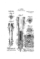
Figure 1 represents in side elevation, a grenade embodying a preferred form of my invention.
Fig. 2 represents an enlarged, central, vertical, sectional elevation through the grenade Fig. 3 represents a fragmentary enlarged detail of the lower portion of the gun-shell particularly illustrating the its adjuncts and a part of the head of the penetrating nose. In all of place. Fig. 4 represents a top plan view of' the grenade as represented in Fig. 1.
Fig. 5 represents a sectional top` plan through the grenade of Fig.A 2 on the plane of the dotted line 5 -5 of said Fig. 2.
Fig. 6 l plan View on the line (5e-6 of Fig. 2.
Fig. 7 represents a View similar to that of Fig. 2, indicating, however, the position of the parts when the grenade has been represents a similar sectional top Afrom its axis, as shown earth serve both to prevent l dropped and plunged into the ground and' when the bomb-.expelling charge has shot the bomb almost clear of the gun-shell.
Fig. l 8' represents a perspective of the flanged collar of the bomb' removed from the bomb and viewed from on top.
Fig. 9 represents a similar View of the collar viewed from underneath.
Fig. 10 represents a perspective view of one of the delay fuses.
V Fig'. 11 represents a perspect1ve, v1ewed from above, of the primary charge cap revmoved from the breech block.
Fig. 12 represents a similar view of the same,viewed from the bottom. I
Similar numerals of reference indicate corresponding parts. I
Referring to the drawings v 1 designates a shell or casing which I term the gun-shell, within which is contained the bomb or torpedo 2. This gun-shell is a cylinder of sheet metal, at its upper or outer end formed with stabilizing wings or blades are preferably formed by stamping outlongitudinal segmental sections of the shell so that they protrude diametrically outward particularly in Fig. 4. They may, of course, be separately attached.
At its lower or striking end, the Vshell isV slotted or cut longitudinally so as .to form what I term spreading flanges 4, any desired plurality of which may be formedA by slots 5 of desired breadth stamped out of the substance of the walls of the shell. These flanges when spread by contact with the too deep penetration and to anchor the shell. y
Within the lower or outward end of the shell is inserted' a gun-breech-mechanism, or
This breech block fills the interiorl of the lowerl end-portion of the shell, is cylindric and conveniently secured permanently withpreferably but not necessarily by being formed with circumferential external grooves 7 into which the walls of the into the circumferential internal beads 8, which lill within the grooves of the breech.
The upper portion of the breech is hol- .lowed out to `form an enlarged vchamber which I term the explosive chamber 9, within which is contained the bomb-expelling charge of any preferred explosive 10.
The lower portion of the breech is hollowed out to form a nose-chamber 11,'prefer' ably cylindric, within which is entered and located the head portion or head-block 12 of the penetrating nose 13 which latter is of conical form and preferably protrudes from the lower open end of the gun shell,-being in part, or as to its comcal or tapering area,
shell are'forced or crimped by being formedv -tion between the breech-mechanism and the preferably encompassed by the spreading anges 4, and in part, or as to its cylindric basal area l4.,preferably fitted within what I call a base-chamber 15 of the breech block. The head-block 12er upper portion ofthe 70 nose is upon its upper' innersurface-formed or provided with a firing pin 16 to strike and ire the explosive c'ap 17. v
The nose-piece 13, it will be observed, acts.l 1n conjunction with 4.flanges 4 to stop the descent of the shell through'the earth, since. the nose-piece forces the earth between the same and the flanges, outwardly against the anges, to spread the latter apart. y From the foregoing construction, it results that thevnose piece as an entirety is so related to the nose chamber 11 and the base and of course with respect to the gun-shell, Y
and that the device constitutes a firing mechamsm.
The nose is normally retained in the osition represented in Figs.' 1, 2, 3 and 6, by a cotter pin 18, which is entered within and through a diametrically located pin tube 19 of copper or other relatively soft sheet metal, which passes through a cylindricgbore 20 drilled diametrically through the breech block and a correspondent bore 21 drilled through the head block 12 of\the nose 1 3,- so that in the assembling of the partst the two bores register and permit of the :fixed y introduction of the pin tube through'them 100 botl 1, so as to normally retain the nose in the position represented in Figs. l, 2. and 3, the,` cotter pin which, as stated, is introduced through the pin tube 19, assuring the retention of the nose.
Assume the cotter pin first withdrawn from its tube when the grenade is dropped, and the nose still remaining in the position represented in Fig. 1,-it is obvious that vunder these conditions the upward and inward driving of the nose such as will be occasioned when it strikes the ground or other object tobe encountered, will cause the soft pin tube'to be cut through and so permit of the driving up of the nose, as shownV in Fig. 7, until its firing pin 16 encounters the fuse capV 17 and ex lodes it.v This device is, therefore, a breakab' e connecfiring-mechanism. A Y
Below the explosive chamber 9, and axial of and w1th1n .the breech, is formed what I -term the primary delay-chamber 22, preferably cylindric and internally threaded, within which is secured-what I term a pri- 125 mary charge-cup v23, which is of pill-box form and perforated through its bottom by thefp'erforations 24, as will be understood from Figs. A11 and 12.A
Within this primary charge-cup is insion of which y chamber 28 yin the Y 27 into the central perforation 26 of the primary delay fuse 25, will occasion the explosion of such fuse upwardly through the perforations 23 and into the bomb-expelling charge 10 within the explosion chamber 9, so as to l both it and the top closure 31 of the bomb.
explode said charge.A
The bomb or torpedo 2, a hollow cylindric shell or casing, is formed with an inter'- nal bomb-chamber 29 within which is contained the bomb-bursting-explosive 30. The bombchamber 29 is closed at its upper or innerl end by the closure 31, and is open at its lower end and formed with acircumferential shoulder 32, Fig. 7, and with a tubular externally-threaded downward extension 33, which is fitted to be threaded within a threaded upper opening 34 of the breech block, so that in the introduction ofthe torpedo within the gun, the torpedo is screwed and so secured to vthe breech block.
The threads which form the threaded ,connection between the torpedo and the breech block are, however, 4of slight depth, so that in the explosion of the bomb expelling charge 10, they may \be readily stripped or drawn apart to set the bomb free. Other forms of readily detachable connection may, however, be resorted to.
`Within the lower open end of the bomb is introduced a secondary delay fuse 35, the explosion of which occurs after the explosion of the bomb-expelling charge 10, and occasions the explosion of the bursting explosive charge 30 within the bomb.
This secondary delay fuse is conveniently a reverse counterpart of theprimary delay 1fuse vand is applied and formed as folrows:
. 36 is a retaining flanged. collarv shown in d Figs. 8 and 9, also of pill-box shape an through its bottom.
This cap-like collar 36 is externally threaded and is preferably adapted to be screwed into the lower threaded open end.
ofthe bomb, Fig. 7, so that it fills in the open bottom of the bomb chamber 29 and confines the bursting explosive 30 between Within this retaining collar 36 isintroduced, preferably by being threaded in, a secondary charge cup 38 generally counterpart of the primary charge cup 23 but 24 in the primary charge cup' jso, as explained. ltouched formed `with a central ring hole 37.-
successive explosive charges :-iirst, that of the fuse of the explosive cap 17 which is set 0H by the stroke of the firing pin 16 when the grenade has encountered the ground or other object to be struck and its nose has been not only driven into the ground or object but also forced inwardly and upwardly to touch voff said explosive cap ,-second,
that what I have called the primary delay fuse 25, which is set off by the explosion of the cap fuse and in `turn operates upon the bomb-expelling charge to set it od ;-third, the bomb-expelling charge 9` itself, which when set off, sets off the secondary delay fuse 35;-fourth, the secondary delay fuse,
off by the bombexpelling charge and which in turn sets o the charge of bursting explosive 30 within the bomb ;-and,vifth, the charge of bursting explosive within the bomb.
1t is of the essence of my invention that the timing or order of discharge of these five explosive charges should be both definite and in predetermined successive order and this is insured by the selected character of the explosives themselves.
Thus, the discharge of the explosive cap cannot vtake. place until the grenade as an entirety .has embedded itself" to a certain distance within the ground or object to be struck, and so has driven the penetrating nose backward int-o the shell.
The driving .of the nose into the ground also and lat the same time occasions the expansion of the spreading Yflanges of the gun-shell by the forcing out action of the earth or other substance of the obj ect-struck bet-Ween the conical surfaces of the nose and the internal surface of the flanges, so as to occasion the spreading out of the flanges in the manner typified in Fig. 7, and to further prevent the too deep sinking in of the grenade and occasion the retention of its lower portion within the ground or other object struck, as clearly shown in said figure. Thus, further, the explosion of the primary delay fuse which takes place as the result of the 'explosion of the fuse cap, is a delayed charge which for a small fraction of a second delays the explosion of the bomb-expelling charge adapted to be reversely disposed. This cup 10, the explosion of which latter is sufficient to light-but not to e'xplodethe secondary delay fuse which later on occasions the exriod, calculated, however, not to take place,
plosion of the bomb when completely ejected' from out the upper end of the gun shell.
Thus, further, the explosion of the secondary delay fuse or charge is a delayed explosion taking place within a very short peand -so occasion the explosion of the bursting explosive'and of the bomb, until after the bomb has cleared the gun shell some predetermined distance, say, for instance, some .A eight or ten feet.
In speaking of delayed explosions, it is to be understood that in the art of compoundtheir successive disposition within the shell. Y 2
ing and making various explosive mixtures,
it is possible to make them of 'such charac-v Thus, when-the gun shell has plunged a given distance into the .ground and?,y its place until after the bomb has been expelledv explosion will be that of spreading an'ges have been s'pread as shown 1n Fig. 7 so as to retain it in that position;
and when, also, the penetrating nose has been driven inward and upward, the-first the fuse cap 17 the second, that of thel primary delay charge 25,-the third, that of the bomb-expelling charge 10, which will occasion the expulsion f Yofthe bomb.,the fourth, that of the secondary delay charge 85 which will not take a predetermined distance out of the gun shell,- -and, fifth and last, that ofthe bursting charge 30 occasioned by the explosion of the secondary delay charge and resulting in the explosion of the bomb wholly above and beyond the gun shell and not within the ground where its explosion 'would be less effectual.
Having thus described myinvention, what I claim as new and desire to secure by Letters Patent, is :-l 1. In an aerial grenade, the combination of an outer shell, havingspreading flanges ,at its forward end, and a nose-piece between sald flanges, tapering upwardly and out-l wardly from its lowerend, to force earth outwardly against said flanges to-spread thesame when the grenade strikes the ground, the war nd first. Y
2. In an aerialgrenade, the comblnation of an outer tubular shell, open and providedwith spreading flanges` at its forward end, a
(grenade being constructed to fall for-V e Y Y Y recessed breech-block secured within said shell, la nose-piecel mounted the forward end o f said breech-block and extending be- -tw'een said iangesto be forced upwardly therein by impact againstthe ground, a torpedo within the. shell adapted to be'driven rearwardly therefrom, and normally resting 0n said block, and means operated by upward movement of saidv nose-pieceffor explelilng said torpedo rearwardlyhfrom said s e v Y A3. In an aerial grenade, the combination of an outer tubular'Sheet-metal shell, having stabilizer blades integraltherewith, a breechblock secured withinv the lower end of the same, having a recess in its upper part containing anexpelling charge and a hollow portion, ope-n at the bottom, in its lower". part', a nose piece slidably mounted in said hollow portion, and protruding from ythe forward end'of the shell, a torpedo to the rear of said breech block, means for firing said expelling charge when said nose-piece is driven rearwardly, and means for firing the bursting charge in Vsaid torpedo after an 90 interval of time after the firing of said ex. pelling charge. ,t 4; In an aerial grenade, the combination of an outer tubular shell of sheet-metal having stabilizing blades stamped out from the upper portionv thereof vto extend therefrom "in the axial direction of the shell, a torpedo in said shell, .and means for exploding said torpedo on impact.-
- 5. An aerial grenade, which comprises in combination 'a torpedo-carrying gun-shell, open and provided ywith stabilizers at its rear end, and open and provided with spreading'iianges at its forward end,- a gunbreech-mechanism within the gun-shell,-'a 105' ring mechanism forward ofl the gun-breechmechanism and in the outer end of the gunshell, and consisting of an outwardly protruding nose and a firing pin both within the gun-breech-mechanism,-a breakable con- 110 nection between the firing mechanism and the gun-breech-mechanism,-a torpedowithin the shell detachably connected with the gun-breech-mechanisln and containing a charge of bursting explosive,a firing fuse 115 within the gun-breechmechanism which is exploded when the firing-mechanism encounters an exterior object and after the breakable connection is broken,- -a primary delay fuse in the gun-breech-mechanlsm which is exploded by the explosion of the Y firing fuse,-a bomb-expelling explosive Y charge .within the gun-breech-mechamsm land above the primary delay fuse, which is exploded by the/explosion of the primary delay fuse,a',secondary delay fuse at the forward end ofY-the torpedo which is exploded vby the explosion of the bomb-expelling explosive charge,-anda bursting explosive charge-within the v torpedo which is exploded by the explosion of the. secondary delay fuse.
6. An aerial grenade, which comprises in combination z-a torpedo-carrying gunfshell, open and provided with stabilizers at its rear end, and open and provided with l spreading anges at its forward end,-a gunbreech-mechanism within said shell embodying in successive order a iring fuse, a pr1 mary delay fuse, and a bomb-expelling charge,-a firing mechanism at the forward end of the shell which operates in connecvtion with Vsaid gun-breech-mechanism after an encounter with an exterior object, to re the iring use,-a torpedo within the Ygunshell detachably Y connected with the gunbreech-mechanism.. and embodying in successive order -a secondary -delay fuse and a bursting explosive charge.
7 An aerial grenade, which comprises in combination z-a'torpedo-carrymg gun-shell,
open and provided with stabilizersat its" rear end, and open and provided with spreading flanges at its forward vend,a gun-breech-mechanism within said shell embodying in successive ordera ring fuse, a primary delay fuse, and a bomb-expelling charge,-a firing mechanism at the forward end of the shell which operates in connection withV said gun-breech-mechanism after an encounter firing fuse,- a breakable connection between the firing mechanism and the gun-breechf with an exterior object to fire the' mechanism,.-a torpedo within the gun-shell detachably connected with the gun-breechmechanism and embodying in successive order a secondary delay fuse and a bursting having a firing pinyat its upper .inner end,
a breakable connection between the firing mechanism and the gun-breechmechanism, atorpe'do within the shell detachably connected with the gun-breech-mechanism and embodying in successive order a secondary delay fuse and a bomb-expelling explosive charge.V l v A v In testimony whereof I have hereunto signed my name this fourteenth day of. June,
LESTER n isAnLow.
In the presence of- J. BoNsALL TAYLOR, JOHN A.
Priority Applications (1)
| Application Number | Priority Date | Filing Date | Title |
|---|---|---|---|
| US10420916A US1237012A (en) | 1916-06-17 | 1916-06-17 | Aerial hand-grenade. |
Applications Claiming Priority (1)
| Application Number | Priority Date | Filing Date | Title |
|---|---|---|---|
| US10420916A US1237012A (en) | 1916-06-17 | 1916-06-17 | Aerial hand-grenade. |
Publications (1)
| Publication Number | Publication Date |
|---|---|
| US1237012A true US1237012A (en) | 1917-08-14 |
Family
ID=3304831
Family Applications (1)
| Application Number | Title | Priority Date | Filing Date |
|---|---|---|---|
| US10420916A Expired - Lifetime US1237012A (en) | 1916-06-17 | 1916-06-17 | Aerial hand-grenade. |
Country Status (1)
| Country | Link |
|---|---|
| US (1) | US1237012A (en) |
Cited By (6)
| Publication number | Priority date | Publication date | Assignee | Title |
|---|---|---|---|---|
| US2435095A (en) * | 1942-06-24 | 1948-01-27 | Harry J Nichols | Projectile |
| US2449913A (en) * | 1944-04-05 | 1948-09-21 | Schermuly Conrad David | Water-borne flare and the like |
| US2708860A (en) * | 1954-09-09 | 1955-05-24 | Diving Corp | Power spear |
| US3774540A (en) * | 1971-12-01 | 1973-11-27 | Us Navy | Terradynamic brake |
| US4318343A (en) * | 1971-08-19 | 1982-03-09 | The United States Of America As Represented By The Secretary Of The Navy | Dual mode incendiary bomblet |
| US4458596A (en) * | 1982-07-06 | 1984-07-10 | The United States Of America As Represented By The Secretary Of The Navy | Multi-purpose bomblet |
-
1916
- 1916-06-17 US US10420916A patent/US1237012A/en not_active Expired - Lifetime
Cited By (6)
| Publication number | Priority date | Publication date | Assignee | Title |
|---|---|---|---|---|
| US2435095A (en) * | 1942-06-24 | 1948-01-27 | Harry J Nichols | Projectile |
| US2449913A (en) * | 1944-04-05 | 1948-09-21 | Schermuly Conrad David | Water-borne flare and the like |
| US2708860A (en) * | 1954-09-09 | 1955-05-24 | Diving Corp | Power spear |
| US4318343A (en) * | 1971-08-19 | 1982-03-09 | The United States Of America As Represented By The Secretary Of The Navy | Dual mode incendiary bomblet |
| US3774540A (en) * | 1971-12-01 | 1973-11-27 | Us Navy | Terradynamic brake |
| US4458596A (en) * | 1982-07-06 | 1984-07-10 | The United States Of America As Represented By The Secretary Of The Navy | Multi-purpose bomblet |
Similar Documents
| Publication | Publication Date | Title |
|---|---|---|
| ES2298520T3 (en) | DEVICE FOR DEACTIVATING EXPLOSIVE ARTEFACTS. | |
| US1300333A (en) | Explosive shell. | |
| CA1171733A (en) | Practice projectile | |
| US8468946B2 (en) | Low shrapnel door breaching projectile system | |
| US4488490A (en) | Percussion initiated spotting charge | |
| DE4225704A1 (en) | Warhead with a tandem charge | |
| US8413586B2 (en) | Door breaching projectile system | |
| KR100915706B1 (en) | 40mm training shot of a grenade launcher | |
| DE106263T1 (en) | ARMORED BULLET BLOCK PROVIDED WITH A DRIVE SLEEVE. | |
| US1237012A (en) | Aerial hand-grenade. | |
| NO316339B1 (en) | Br degree no degree stainless, ballistic blasting projectile | |
| DE3823823A1 (en) | SKULL HEAD | |
| CN105664407A (en) | Fire-fighting projectile | |
| US1235637A (en) | Aerial mortar. | |
| US2454281A (en) | Antipersonnel artillery mine | |
| US2137436A (en) | Explosive device | |
| RU159193U1 (en) | Shot with a shell simulator | |
| US1875985A (en) | Projectile | |
| RU2622063C2 (en) | Game bullet | |
| US4030418A (en) | Gravity deployed mine with combined upper clearing charge firing and delayed main charge initiation | |
| US8297190B1 (en) | Door breaching device with radially expandable explosive | |
| US11287236B1 (en) | Training cartridge with day/night/thermal visible signature | |
| US3289588A (en) | Caliber 50 spotting bullets | |
| US3289589A (en) | Caliber .50 spotting bullets | |
| US1343036A (en) | Aerial bomb |