US1235856A - Ornithopter. - Google Patents
Ornithopter. Download PDFInfo
- Publication number
- US1235856A US1235856A US7013916A US7013916A US1235856A US 1235856 A US1235856 A US 1235856A US 7013916 A US7013916 A US 7013916A US 7013916 A US7013916 A US 7013916A US 1235856 A US1235856 A US 1235856A
- Authority
- US
- United States
- Prior art keywords
- wings
- wing
- pivoted
- sections
- wing sections
- Prior art date
- Legal status (The legal status is an assumption and is not a legal conclusion. Google has not performed a legal analysis and makes no representation as to the accuracy of the status listed.)
- Expired - Lifetime
Links
- 230000033001 locomotion Effects 0.000 description 20
- 238000010276 construction Methods 0.000 description 3
- 238000010009 beating Methods 0.000 description 2
- IWEDIXLBFLAXBO-UHFFFAOYSA-N dicamba Chemical compound COC1=C(Cl)C=CC(Cl)=C1C(O)=O IWEDIXLBFLAXBO-UHFFFAOYSA-N 0.000 description 2
- 239000004744 fabric Substances 0.000 description 2
- 210000003746 feather Anatomy 0.000 description 2
- 230000005484 gravity Effects 0.000 description 2
- 230000006835 compression Effects 0.000 description 1
- 238000007906 compression Methods 0.000 description 1
- 230000003247 decreasing effect Effects 0.000 description 1
- 230000000694 effects Effects 0.000 description 1
- 239000000463 material Substances 0.000 description 1
- 239000002184 metal Substances 0.000 description 1
Images


Classifications
-
- B—PERFORMING OPERATIONS; TRANSPORTING
- B64—AIRCRAFT; AVIATION; COSMONAUTICS
- B64C—AEROPLANES; HELICOPTERS
- B64C33/00—Ornithopters
- B64C33/02—Wings; Actuating mechanisms therefor
Definitions
- FRANK EZRA SUMMERS OF MEMPHIS, MISSOURI.
- My invention relates to flying machines, and particularly to sustaining and propelling means of the ornithopter type for such machines.
- One object of my invention is to provide a sustaining and propelling surface comprising flapping wings having pivoted sections adapted to partially or wholly close on the down stroke and to feather or open fully on the up stroke, whereby a lifting and sustaining thrust is obtained on the down stroke and the wings permitted to move upward on the return stroke without material resistance while maintaining the continuity of flight of the machine.
- a further object of the invention is to provide flapping wings having pivoted wing sections which are adjustable, so that the ratio of lift to thrust can be changed during flight ⁇ or travel.
- a further object ofthe invention is to provide iiapping wings in which the lift and thrust are normally balanced, but in which the lift and thrust can be unbalanced during travel to stabilize the machine or to bank the machine for a turning action.
- a still further object of the invention is to provide iiapping wings with pivoted feathering sections which are adjustable to vary the curvature or pitch of the wing so as to vary its sustaining and propulsivel
- YA still further object of the invention is to provide lflapping wings with pivoted wing sections which are adjusted to working positions and' feathered byfair pressure, which are controllable to vary their working pitch or inclination, and which are yieldingly lcontrolled in their feathering, actions., c
- a still further object of the invention is to provide means for limiting 'the movements of the wing sections to working' position," and tovary their working pitch oil angle, and for adjusting the wing sections to change their working angles relative to one another, 'and to provide means for resiliently balancing the wings.
- a still further objectief the invention is to provide a supporting surface whereby the machine may be caused to Vhover or travel at any given speed.
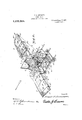
- Figure 1 is a top plan view of a supporting and propelling surface of the ornithopter type embodying my invention.
- Fig. 2 is a rear perspective view of the same.
- Fig. 3 is a vertical longitudinal section on line 3-3 of Fig. l.
- Fig. 4f is a top plan view, with portions broken away, of one of the wings on an enlarged scale.
- Fig. 5 is a vertical fore-and-aft section through one of the wings, showing the feathering action of the pivoted wing sec'- tion on the upward motion o-f the wing.
- Fig. 6 is a similar view showing the pivoted wing section in working position as on the descent of the wing.V
- Fig. 7 is a front elevation of the main l frame showing the mode of mounting the i'iapping wings.
- 1 designates the main frame of the machine, which may be of any suitable construction, and which includes parallel longitudinally extending frame bars 2, 3 ande, which are suitably connected and reinforced and braced.
- frame bars 2, 3 ande Arranged on opposite sides of the frame and hinged or pivoted to the bar 2 so as to swing in a vertical plane, are beating or flapping wings 5 and 6, the frames of the 4rigid portions of said wings being stayed or reinforced from the frame l by truss wires 8 having suitable tensioning devices or turn buckles 8.
- a truss bracket ⁇ 9 is rigidly connected to the frame l and reinforced therefrom by stays 9.
- Flexible connections l0 are also provided between the 'truss brackets' and the wingsV and include coiled springsv 1l, whereby the weightof the wings is balanced, thus allowing said wings to' beV easily operated.
- the wings may be vibrated or oscillated in a vertical plane by manual or motive power'of any suitable character, it being understood that suitable operating devices to enable the aviator to operate the wings may be employed,v as in my prior motive power plant may be employed.
- a aviators or pil'ots seat 12 1s supported upon the frame 1 and. other seats, or a car structure may be employed so that, in addition to the aviator,v
- one or more passengers may be carried.
- Each wing 5 vand. 6 comprises a frame formed: of front and rear wing spars 13 and 14, and suitable cross pieces 15, together with any preferred: type of bracing, the framework of the imperforate portions of the wings being provided with any suitable covering 16 of fabric or metal.
- the wings are preferably rigid and imperforate, while the outer portions of the wings are perforate and completed by hinged or pivoted wing sections 18 and 19;
- the wings are curved on a desired" radius longitudinally, or transversely to the line of flight, and are also curvedfin.
- the fore-and-aft curvature being preferably parabolical, so that the under surface of each wingY will beconcaved in both directions to confine the air against too rapid lateral esca-pe, while at the same ⁇ time providing for the aerodynamic compression of the air and the disposition of the wings at the proper angle of incidencefor a sustaining action.
- the curvature of the wings isY such,V that on each downward or beating motion of the wings both a. lifting thrust and a propelling thrust are obtained, to sustain. the machine in flight as well as propel it through the air.
- the pivoted wing sections18 and 119y are hinged-or pivoted at a point between their leadingI edgesfandv center of gravity to the front wing spar 13, so aste providefor a proper distribution of the load weight carried by the supporting surface, and coincidence of the centers of gravity and pressure.
- rlhe wing sections18 and 19 are preferably of the same structure as the body of the wing, each comprising a frame work and a suitable fabric or metallic covering tO diminish skin friction and air resistance, the distance between the pivotal point of each wing and. itstrailing edge being lessthan the distance between the wing spars 13 and 14 so that the pivoted winglsections are .adapted to swing vertically through the open portion of the wing'frame, asclearly shownin Figs. 5 and 6.
- stop bars 20 which are spring connected tothe front spar 13 of each wing, the spring connection"tending to move the stop bars upward and away' from the rear sparslt.
- the position of the stop bars may be controlled by means of a cable 21, the branched ends Vof which. are connected to stop bars 20, and
- the cable 21 runs, from the right hand wing' stop bars, vover-guide pulleys 22, to the lever 28. to. which it is connected', and from lever 28, over guide pulleys 3Oandy 22, to the left hand wing stop bars. 1t is clear thatby operating lever 28', one end of cable 21y will have a; pull'l'exerted on it, tlinsA pull,- ing down the stop bars 20 and decreasing the extent of upward flapping of one wing, while theother end of; the cable will be released, thusall'owing the st op bars 2O ⁇ of ⁇ the other wing tov spring-y upward, thereby in,h creasing the eXtentof flapping of,l said; other wing;
- aA lever 23 engaging a, rack 25-bymeans of a locking dog24 is provided.
- the lower-end of.' vlever, 23,y pilvotally carries. aL link.y 30, which, by meansofvr a pulley302 on. its end, engages a bight 29,. formedl incable' 21- betweenfthe pulleys 30.
- Elastic connections 26, including coiled spring 27, couple the pivoted wing sections .tofthe-wingframes, and serve tolimit the downward swinging,y or feathering movements of the pivoted wing'sections, and'provide for-their initial movement through the reactionk of the springs in the startingv ofthe wing sections ontheir working motion.
- Theinvention isprimarily designed, how-ever, for use in amotor drivenanachine of the ornithopter type, wherebyornithop- Aters or flapping ⁇ wingl machines; mayk be operated with .greater facility and eiiiciency and greater lifting, propelling and controlling power obtained, it being evident from the foregoing description that my invention provides a construction which is adapted to aiford reliable and eiiicient service in these connections.
- I have shown the wings connected by links or pitmen rods 31 with crank disks 32 on the shaft of a driving motor 33, whereby said wings are given a vibratory motion.
- Supporting and propelling means for ying machines comp-rising a framework, vertically movable wings hinged or pivoted to the framework, each wing having a vertically movable section hinged at its forward edge thereto, means for vibrating the wings, spring mounted stop bars for limiting the upward movement of the hinged wing sections, means for simultaneously adjusting the bars associated with both movable Wing sections to limit the upward movement of said movable win sections, and means for simultaneously adjusting the bars to effect adjustment of the respective movable wing sections in opposite directions.
- a supporting and propelling means for flying machines comprising a frame structure, pivoted vertically movable wings, each having a pivoted wing section hinged for vertical movements, means for permitting feathering motions of the pivoted wing sections on the downward movement of the wings, means for adjustably limiting the upward movement of the wing sections to working position on the downward movement of the wings, and controlling means whereby the pivoted wing sections may be adjusted to different angular or unbalanced positions, said means being adapted to simultaneously adjust said limiting means of both wing sections in the same or diiferent directions.
- Supporting and propelling means for flying machines comprising a framework, pivotally vertically movable wings, each having a pivoted vertically movable section, means for permitting feathering motion of the pivoted wing sections on the upward motion of the wings, adjustable stop devices for limiting the pivoted wing sections on their upward movements to working positions in the downward movements of the wings, means for adjusting the right and left hand stop devices in the same direction in unison, and means for adjusting the right and left hand stop devices in opposite directions in unison.
Landscapes
- Engineering & Computer Science (AREA)
- Aviation & Aerospace Engineering (AREA)
- Toys (AREA)
Description
F.'E. SUMMERS.
V ORNITHOPTER.
APPLICATION FILED IAN. 4. i916v attofcnu v F. E. SUMMERS.
ORNITHOPTER.
APPLICATION FILED 11111.11. 1916` 1,235,856. Patented Aug. 7, 1917.
3 SHEETS-SHEET 2.
F. E. SUMMERS.
ORNITHOPTER.
APPucATloN FILED 1AN.4,19|6.
1,235,856., v Patented Aug. -7,1917.
3 SHEETS-SHEET 3.
Wmme@ m Eran 7a: ESwmnzers,
action.
FRANK EZRA SUMMERS. OF MEMPHIS, MISSOURI.
ORNITHOPTER.
` Specification of Letters Patent.
Patented Aug. '7, 1917.
Application iled January 4, 1916. Serial No. 70,139.
To all whom t may concern:
Be it known that I, FRANK E. SUMMERS, a citizen of the United States, residing at 'Memphis in the county of Scotland and State of Missouri, have invented new and useful Improvements in Grnithopters, of which the following is a specilication.
My invention relates to flying machines, and particularly to sustaining and propelling means of the ornithopter type for such machines.
One object of my invention is to provide a sustaining and propelling surface comprising flapping wings having pivoted sections adapted to partially or wholly close on the down stroke and to feather or open fully on the up stroke, whereby a lifting and sustaining thrust is obtained on the down stroke and the wings permitted to move upward on the return stroke without material resistance while maintaining the continuity of flight of the machine.
A further object of the invention is to provide flapping wings having pivoted wing sections which are adjustable, so that the ratio of lift to thrust can be changed during flight `or travel. Y
A further object ofthe invention is to provide iiapping wings in which the lift and thrust are normally balanced, but in which the lift and thrust can be unbalanced during travel to stabilize the machine or to bank the machine for a turning action.
A still further object of the invention is to provide iiapping wings with pivoted feathering sections which are adjustable to vary the curvature or pitch of the wing so as to vary its sustaining and propulsivel YA still further object of the invention is to provide lflapping wings with pivoted wing sections which are adjusted to working positions and' feathered byfair pressure, which are controllable to vary their working pitch or inclination, and which are yieldingly lcontrolled in their feathering, actions., c
A still further object of the invention is to provide means for limiting 'the movements of the wing sections to working' position," and tovary their working pitch oil angle, and for adjusting the wing sections to change their working angles relative to one another, 'and to provide means for resiliently balancing the wings.
A still further objectief the invention is to provide a supporting surface whereby the machine may be caused to Vhover or travel at any given speed.
With these and other objects in-view, the invention consists of the features of construction, combination and arrangement of parts herein fully described and claimed, reference being had to the accompanying drawings in which Figure 1 is a top plan view of a supporting and propelling surface of the ornithopter type embodying my invention.
Fig. 2 is a rear perspective view of the same.
Fig. 3 is a vertical longitudinal section on line 3-3 of Fig. l.
Fig. 4f is a top plan view, with portions broken away, of one of the wings on an enlarged scale.
Fig. 5 is a vertical fore-and-aft section through one of the wings, showing the feathering action of the pivoted wing sec'- tion on the upward motion o-f the wing.
Fig. 6 is a similar view showing the pivoted wing section in working position as on the descent of the wing.V
Fig. 7 is a front elevation of the main l frame showing the mode of mounting the i'iapping wings. v l
Referring to the drawings, 1 designates the main frame of the machine, which may be of any suitable construction, and which includes parallel longitudinally extending frame bars 2, 3 ande, which are suitably connected and reinforced and braced. Arranged on opposite sides of the frame and hinged or pivoted to the bar 2 so as to swing in a vertical plane, are beating or flapping wings 5 and 6, the frames of the 4rigid portions of said wings being stayed or reinforced from the frame l by truss wires 8 having suitable tensioning devices or turn buckles 8. A truss bracket`9 is rigidly connected to the frame l and reinforced therefrom by stays 9.
Flexible connections l0 are also provided between the 'truss brackets' and the wingsV and include coiled springsv 1l, whereby the weightof the wings is balanced, thus allowing said wings to' beV easily operated.
In practice, the wings may be vibrated or oscillated in a vertical plane by manual or motive power'of any suitable character, it being understood that suitable operating devices to enable the aviator to operate the wings may be employed,v as in my prior motive power plant may be employed. In` Y the present instance an aviators or pil'ots seat 12 1s supported upon the frame 1 and. other seats, or a car structure, may be employed so that, in addition to the aviator,v
one or more passengers may be carried.
Each wing 5 vand. 6 comprises a frame formed: of front and rear wing spars 13 and 14, and suitable cross pieces 15, together with any preferred: type of bracing, the framework of the imperforate portions of the wings being provided with any suitable covering 16 of fabric or metal. rEhe inner portions 17 ofA the wings are preferably rigid and imperforate, while the outer portions of the wings are perforate and completed by hinged or pivoted wing sections 18 and 19; The wings are curved on a desired" radius longitudinally, or transversely to the line of flight, and are also curvedfin. a fore-and-aft direction, or between their lead and trail edges, the fore-and-aft curvature being preferably parabolical, so that the under surface of each wingY will beconcaved in both directions to confine the air against too rapid lateral esca-pe, while at the same `time providing for the aerodynamic compression of the air and the disposition of the wings at the proper angle of incidencefor a sustaining action. The curvature of the wings isY such,V that on each downward or beating motion of the wings both a. lifting thrust and a propelling thrust are obtained, to sustain. the machine in flight as well as propel it through the air. Y
The pivoted wing sections18 and 119y are hinged-or pivoted at a point between their leadingI edgesfandv center of gravity to the front wing spar 13, so aste providefor a proper distribution of the load weight carried by the supporting surface, and coincidence of the centers of gravity and pressure. rlhe wing sections18 and 19 are preferably of the same structure as the body of the wing, each comprising a frame work and a suitable fabric or metallic covering tO diminish skin friction and air resistance, the distance between the pivotal point of each wing and. itstrailing edge being lessthan the distance between the wing spars 13 and 14 so that the pivoted winglsections are .adapted to swing vertically through the open portion of the wing'frame, asclearly shownin Figs. 5 and 6.
On the downward or working stroke of each wing, the pivoted wing sections 18 and 19'Nswing'upwardly at a desired working `angle andy compress the4 air beneath them for sustaining and propelling impulses, as shown in Fig. 6, while onthe upward movement of the wings the pivotedl wing sections 18 and *1,9l swing downward under the pressure-of the air from above, so that they will feather or travel ,edgewise in a substantially vertical position, as shown in- Fig. 5.
The upward swinging movements of the pivoted wing sections are limited by stop bars 20, which are spring connected tothe front spar 13 of each wing, the spring connection"tending to move the stop bars upward and away' from the rear sparslt. The position of the stop bars may be controlled by means of a cable 21, the branched ends Vof which. are connected to stop bars 20, and
which may be operated topull: said. bars towardl 'spars 14 against the tensioni of the spring connections.
The cable 21 runs, from the right hand wing' stop bars, vover-guide pulleys 22, to the lever 28. to. which it is connected', and from lever 28, over guide pulleys 3Oandy 22, to the left hand wing stop bars. 1t is clear thatby operating lever 28', one end of cable 21y will have a; pull'l'exerted on it, tlinsA pull,- ing down the stop bars 20 and decreasing the extent of upward flapping of one wing, while theother end of; the cable will be released, thusall'owing the st op bars 2O\of` the other wing tov spring-y upward, thereby in,h creasing the eXtentof flapping of,l said; other wing;
In; order to simultaneously exert a pullV or to release the stop bars 2 0 of both the wings, aA lever 23 engaging a, rack 25-bymeans of a locking dog24; is provided. The lower-end of.' vlever, 23,y pilvotally carries. aL link.y 30, which, by meansofvr a pulley302 on. its end, engages a bight 29,. formedl incable' 21- betweenfthe pulleys 30. VBy;operating lever 23, the effectivev length off cable'21 will beincreased ordecreased andthe stop bars 20fof both wings correspondingly pulled, downl or permitted to spring; up. At the same time, it will.- be noted that; theV lever, 23, owing-to the pulleyl connection- 302, will inr nowise interfere with theoperation of thelever 28,4 so that great latitude inthe simultaneous adjustment ofi the stop bars 20, either similarly orjoppositely, is.- obtained.
In practice, of course, it is to be understood that thel invention may be embodied inV a manual driven or power driven machine orin an ordinary glider structure, the
lwingsbeingoperated in the case of. a glider structure, to give an* initialA starting impulse.. Theinvention isprimarily designed, how-ever, for use in amotor drivenanachine of the ornithopter type, wherebyornithop- Aters or flapping` wingl machines; mayk be operated with .greater facility and eiiiciency and greater lifting, propelling and controlling power obtained, it being evident from the foregoing description that my invention provides a construction which is adapted to aiford reliable and eiiicient service in these connections. In the present instance I have shown the wings connected by links or pitmen rods 31 with crank disks 32 on the shaft of a driving motor 33, whereby said wings are given a vibratory motion.
I claim 1. Supporting and propelling means for ying machines comp-rising a framework, vertically movable wings hinged or pivoted to the framework, each wing having a vertically movable section hinged at its forward edge thereto, means for vibrating the wings, spring mounted stop bars for limiting the upward movement of the hinged wing sections, means for simultaneously adjusting the bars associated with both movable Wing sections to limit the upward movement of said movable win sections, and means for simultaneously adjusting the bars to effect adjustment of the respective movable wing sections in opposite directions.
2. A supporting and propelling means for flying machines comprising a frame structure, pivoted vertically movable wings, each having a pivoted wing section hinged for vertical movements, means for permitting feathering motions of the pivoted wing sections on the downward movement of the wings, means for adjustably limiting the upward movement of the wing sections to working position on the downward movement of the wings, and controlling means whereby the pivoted wing sections may be adjusted to different angular or unbalanced positions, said means being adapted to simultaneously adjust said limiting means of both wing sections in the same or diiferent directions.
3. Supporting and propelling means for flying machines comprising a framework, pivotally vertically movable wings, each having a pivoted vertically movable section, means for permitting feathering motion of the pivoted wing sections on the upward motion of the wings, adjustable stop devices for limiting the pivoted wing sections on their upward movements to working positions in the downward movements of the wings, means for adjusting the right and left hand stop devices in the same direction in unison, and means for adjusting the right and left hand stop devices in opposite directions in unison.
In testimony whereof I aiiiX my signature in presence of two witnesses.
FRANK EZRA sUMMERs.
Witnesses J. M. JAYNE, WILLIAM L. SCOTT.
Copies of this patent may be obtained for ve cents each, by addressing the Commissioner of Patents, Washington, ZD. (2.
Priority Applications (1)
| Application Number | Priority Date | Filing Date | Title |
|---|---|---|---|
| US7013916A US1235856A (en) | 1916-01-04 | 1916-01-04 | Ornithopter. |
Applications Claiming Priority (1)
| Application Number | Priority Date | Filing Date | Title |
|---|---|---|---|
| US7013916A US1235856A (en) | 1916-01-04 | 1916-01-04 | Ornithopter. |
Publications (1)
| Publication Number | Publication Date |
|---|---|
| US1235856A true US1235856A (en) | 1917-08-07 |
Family
ID=3303678
Family Applications (1)
| Application Number | Title | Priority Date | Filing Date |
|---|---|---|---|
| US7013916A Expired - Lifetime US1235856A (en) | 1916-01-04 | 1916-01-04 | Ornithopter. |
Country Status (1)
| Country | Link |
|---|---|
| US (1) | US1235856A (en) |
-
1916
- 1916-01-04 US US7013916A patent/US1235856A/en not_active Expired - Lifetime
Similar Documents
| Publication | Publication Date | Title |
|---|---|---|
| US821393A (en) | Flying-machine. | |
| US1235856A (en) | Ornithopter. | |
| US1845913A (en) | Flying device | |
| US1766330A (en) | Flying machine | |
| US910683A (en) | Air-ship. | |
| US1192954A (en) | Flying-machine. | |
| US1004058A (en) | Flying-machine. | |
| US1202449A (en) | Flying-machine. | |
| US980489A (en) | Flying-machine. | |
| US1135009A (en) | Flying-machine. | |
| US1049498A (en) | Flying or soaring machine. | |
| US981714A (en) | Aeroplane flying-machine. | |
| US1014857A (en) | Flying-machine. | |
| US1009157A (en) | Flying-machine. | |
| US1011139A (en) | Aeroplane. | |
| US1127167A (en) | Aeroplane. | |
| US919834A (en) | Flying-machine. | |
| US992579A (en) | Flying-machine. | |
| US688135A (en) | Air-ship. | |
| US1069823A (en) | Flying-machine. | |
| US1011519A (en) | Alaeplane. | |
| US1022018A (en) | Flying-machine. | |
| US1014194A (en) | Aeroplane. | |
| US1657669A (en) | Flying machine | |
| US840078A (en) | Air-ship. |