US12355240B2 - Failure detection within a group of power flow control modules - Google Patents
Failure detection within a group of power flow control modules Download PDFInfo
- Publication number
- US12355240B2 US12355240B2 US18/486,292 US202318486292A US12355240B2 US 12355240 B2 US12355240 B2 US 12355240B2 US 202318486292 A US202318486292 A US 202318486292A US 12355240 B2 US12355240 B2 US 12355240B2
- Authority
- US
- United States
- Prior art keywords
- iim
- response
- command
- target
- flow control
- Prior art date
- Legal status (The legal status is an assumption and is not a legal conclusion. Google has not performed a legal analysis and makes no representation as to the accuracy of the status listed.)
- Active, expires
Links
Images


Classifications
-
- H—ELECTRICITY
- H02—GENERATION; CONVERSION OR DISTRIBUTION OF ELECTRIC POWER
- H02J—ELECTRIC POWER NETWORKS; CIRCUIT ARRANGEMENTS OR SYSTEMS FOR SUPPLYING OR DISTRIBUTING ELECTRIC POWER; SYSTEMS FOR STORING ELECTRIC ENERGY
- H02J3/00—Circuit arrangements for AC mains or AC distribution networks
- H02J3/001—Arrangements for handling faults or abnormalities, e.g. emergencies or contingencies
- H02J3/0012—Arrangements for handling faults or abnormalities, e.g. emergencies or contingencies characterised by the contingency detection means in AC networks, e.g. using phasor measurement units [PMU], synchrophasors or contingency analysis
-
- H—ELECTRICITY
- H02—GENERATION; CONVERSION OR DISTRIBUTION OF ELECTRIC POWER
- H02J—ELECTRIC POWER NETWORKS; CIRCUIT ARRANGEMENTS OR SYSTEMS FOR SUPPLYING OR DISTRIBUTING ELECTRIC POWER; SYSTEMS FOR STORING ELECTRIC ENERGY
- H02J13/00—Circuit arrangements for providing remote monitoring or remote control of equipment in a power distribution network
- H02J13/13—Circuit arrangements for providing remote monitoring or remote control of equipment in a power distribution network characterised by the transmission of data to equipment in the power network
- H02J13/1321—Circuit arrangements for providing remote monitoring or remote control of equipment in a power distribution network characterised by the transmission of data to equipment in the power network using a wired telecommunication network or a data transmission bus
- H02J13/1323—Circuit arrangements for providing remote monitoring or remote control of equipment in a power distribution network characterised by the transmission of data to equipment in the power network using a wired telecommunication network or a data transmission bus using optical fibres
Definitions
- FIG. 1 is a block diagram illustrating the conventional use of impedance injection modules in a power transmission system.
- power transmission system 100 includes a long power transmission line 105 , a generator 101 , a load 102 , transformers 105 - 01 and 105 - 02 , and multiple impedance injection modules 110 (shown as 110 - 01 , . . . , 110 - nn ).
- Long power transmission line 105 is used for power transmission between generator 101 and load 102 .
- Generator 101 and load 102 are connected or coupled to one another using transformers 105 - 01 and 105 - 02 .
- Impedance injection modules 110 are connected to transmission line 105 .
- Impedance injection modules 110 are used to improve the transmission's power factor, reliability, and efficiency.
- the impedance injection modules 110 are shown to be connected in series, though they can also be connected in parallel (shunt) or a combination of series and shunt.
- FIG. 1 shows a single-phase system, though typical transmission line systems are three-phased.
- FIG. 1 is a block diagram illustrating the conventional use of impedance injection modules in a power transmission system 100 .
- FIG. 3 is a block diagram illustrating a power line coordinator used in the system of FIG. 2 according to an embodiment.
- FIG. 5 is a flow diagram illustrating a process performed by the power line coordinator according to an embodiment.
- FIG. 6 is a flow diagram illustrating a process performed by the impedance injection module according to an embodiment.
- a power flow control system may include impedance injection modules (IIMs) distributed along and connected in series to one or more power transmission lines.
- IIMs impedance injection modules
- the system may further include dual-ring fiber optic networks, with each dual-ring fiber optic network including a pair of fiber rings that provide data flow in opposite directions.
- the system may further include redundant power line coordinators in communication with the IIMs through the dual-ring fiber optic networks.
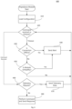
- a method for a power line coordinator may be provided.
- a command or a telemetry data request may be sent to a target IIM. It may be determined whether a response was received from the target IIM. If it is determined that the response was received from the target IIM, the response may be examined to determine whether it includes an alert. If it includes an alert, the alert may be analyzed, and a power flow control system may be reconfigured and configuration information of the power flow control system may be saved based on it.
- a method for an impedance injection module It may be determined whether a command has been received within a time period. In response to determining that the command has been received within the time period, it may be determined whether the command is a telemetry data request. In response to determining that the command is a telemetry data request, telemetry data collected and measured by the impedance injection module may be sent. Otherwise, in response to determining that the command is not a telemetry data request, the command may be performed and a response is sent.
- FIG. 2 is a block diagram illustrating a system having three dual-ring fiber optic networks connecting a fleet or group of impedance injection modules and a set of redundant power line coordinators according to an embodiment.
- a fleet of impedance injection modules shown as 110 - 01 , 110 - 02 , 110 - 03 , . . . , 110 nn , may be connected to three dual-ring fiber optic networks (labeled 250 - 270 ). It should be understood that while three dual-ring fiber optic networks are illustrated in FIG. 2 , any number of dual-ring fiber optic networks may be implemented within system 200 .
- the impedance injection module 110 may be connected to three-phase power transmission lines (not shown explicitly in the figure) and can be distributed along the power transmission lines. Each impedance injection module 110 may be connected to the three phases of the power transmission lines. For example, in FIG. 2 the three phases are labeled as A, B, and C. Impedance injection module 110 can change the impedance of each phase independently or in a coordinated fashion. Each impedance injection module 110 may operate independently from other IIMs. For example, IIM 110 - 01 can inject impedance on Phase A, whereas IIM 110 - 02 may not inject any impedance, and IIM 110 - 03 may inject impedance on Phase B, etc.
- Each phase of an IIM 110 may be connected to a dual-ring fiber optic network to allow data flow between the IIM 110 and power line coordinators 220 .
- fiber ring 250 a of dual-ring fiber optic network 250 a - b may provide data flow in a counterclockwise direction and fiber ring 250 b of dual-ring fiber optic network 250 a - b may provide data flow in a clockwise direction, or vice versa.
- fiber rings 260 a and 260 b of dual-ring fiber optic network 260 a - b may allow data flow in the counterclockwise and clockwise directions for phase B, respectively.
- fiber rings 270 a and 270 b of dual-ring fiber optic network 270 a - b may provide data flow in the counterclockwise and clockwise directions, respectively. Accordingly, each of dual-ring fiber optic networks 250 a - b , 260 a - b , and 270 a - b may allow data flow in opposite directions.
- redundant power line coordinators (or PLC) 220 -P and 220 -S may coordinate the communication within the fiber rings 250 a - b , 260 a - b , and 270 a - b .
- PLC 220 -P may be a primary power line coordinator, and PLC 220 -S may serve as a secondary power line coordinator.
- PLC 220 -S may take over as the primary power line coordinator in case of a failure of PLC 220 -P.
- PLCs 220 -S and 220 -P may be respectively connected to power supply 235 - 01 and 235 - 02 via a set of redundant power buses (shown as Power Bus 1 and Power Bus 2 ).
- Each of power supplies 235 - 01 and 235 - 02 may include appropriate backup measures, such as a battery, generator, etc., ensuring PLC operation during power supply disruptions.
- PLC 220 -P can issue commands or requests (e.g., telemetry data requests or data requests) to an IIM 110 via a fiber ring in either direction, e.g., using a counterclockwise fiber ring (such as fiber ring 250 a , 260 a , 270 a ) or a clockwise fiber ring (such as fiber ring 250 b , 260 b , 270 b ).
- PLC 220 -P may select a default direction (e.g., counterclockwise) during regular operation.
- PLC 220 -P can issue one or more commands on a per-phase basis.
Landscapes
- Engineering & Computer Science (AREA)
- Power Engineering (AREA)
- Arrangements For Transmission Of Measured Signals (AREA)
Abstract
Description
Claims (20)
Applications Claiming Priority (2)
| Application Number | Priority Date | Filing Date | Title |
|---|---|---|---|
| PK684/2022 | 2022-10-14 | ||
| PK6842022 | 2022-10-14 |
Publications (2)
| Publication Number | Publication Date |
|---|---|
| US20240128748A1 US20240128748A1 (en) | 2024-04-18 |
| US12355240B2 true US12355240B2 (en) | 2025-07-08 |
Family
ID=96259612
Family Applications (1)
| Application Number | Title | Priority Date | Filing Date |
|---|---|---|---|
| US18/486,292 Active 2043-10-17 US12355240B2 (en) | 2022-10-14 | 2023-10-13 | Failure detection within a group of power flow control modules |
Country Status (1)
| Country | Link |
|---|---|
| US (1) | US12355240B2 (en) |
Citations (21)
| Publication number | Priority date | Publication date | Assignee | Title |
|---|---|---|---|---|
| US4369523A (en) | 1979-06-19 | 1983-01-18 | Kokusai Denshin Denwa Co., Ltd. | Remote control system of an optical repeater |
| US4402903A (en) | 1981-09-04 | 1983-09-06 | Westinghouse Electric Corp. | Control system for coupling redundant logic channels |
| US4427620A (en) | 1981-02-04 | 1984-01-24 | Westinghouse Electric Corp. | Nuclear reactor power supply |
| US4661310A (en) | 1983-10-27 | 1987-04-28 | Westinghouse Electric Corp | Pulsed multichannel protection system with saturable core magnetic logic units |
| US5110189A (en) | 1990-11-16 | 1992-05-05 | Tamrock World Corporation | Redundant remote control system used on a continuous miner and method of using same |
| US5136410A (en) | 1990-01-09 | 1992-08-04 | Ibm Corporation | Optical fiber link control safety system |
| US5349457A (en) | 1991-12-19 | 1994-09-20 | Northern Telecom Limited | Fiber optic telephone loop network |
| US5809543A (en) | 1993-12-23 | 1998-09-15 | Unisys Corporation | Fault tolerant extended processing complex for redundant nonvolatile file caching |
| US5894362A (en) | 1995-08-23 | 1999-04-13 | Fujitsu Limited | Optical communication system which determines the spectrum of a wavelength division multiplexed signal and performs various processes in accordance with the determined spectrum |
| US6484126B1 (en) | 1997-06-06 | 2002-11-19 | Westinghouse Electric Company Llc | Digital plant protection system with engineered safety features component control system |
| US6556953B2 (en) | 2001-04-09 | 2003-04-29 | Mcdata Corporation | Automatic testing of redundant switching element and automatic switchover |
| US6690889B2 (en) | 1999-12-30 | 2004-02-10 | Alcatel | Device for compensating polarization dispersion in an optical transmission system |
| US6732656B1 (en) | 2002-09-16 | 2004-05-11 | The United States Of America As Represented By The Secretary Of The Air Force | High voltage tolerant explosive initiation |
| US6821026B2 (en) | 2002-09-04 | 2004-11-23 | International Business Machines Corporation | Redundant configurable VCSEL laser array optical light source |
| US6961306B2 (en) | 2002-07-10 | 2005-11-01 | I/O Controls Corporation | Fiber optic control network and related method |
| US6965560B2 (en) | 2002-07-10 | 2005-11-15 | I/O Controls Corporation | Multi-tier, hierarchical fiber optic control network |
| US7046621B2 (en) | 2002-07-10 | 2006-05-16 | I/O Controls Corporation | Redundant multi-fiber optical ring network |
| US7295572B1 (en) | 2003-03-26 | 2007-11-13 | Cisco Technology, Inc. | Storage router and method for routing IP datagrams between data path processors using a fibre channel switch |
| US7957270B2 (en) * | 2005-06-27 | 2011-06-07 | At&T Intellectual Property I, L.P. | Resilient packet ring protection over a wavelength division multiplexing network |
| US8155516B2 (en) | 2009-05-05 | 2012-04-10 | Alphion Corporation | Apparatus and method for ensuring continuity of fiber optic |
| US8457488B2 (en) | 2008-02-07 | 2013-06-04 | Eci Telecom Ltd. | Technology for providing telecommunication services to multiple optical communication lines |
-
2023
- 2023-10-13 US US18/486,292 patent/US12355240B2/en active Active
Patent Citations (23)
| Publication number | Priority date | Publication date | Assignee | Title |
|---|---|---|---|---|
| US4369523A (en) | 1979-06-19 | 1983-01-18 | Kokusai Denshin Denwa Co., Ltd. | Remote control system of an optical repeater |
| US4427620A (en) | 1981-02-04 | 1984-01-24 | Westinghouse Electric Corp. | Nuclear reactor power supply |
| US4402903A (en) | 1981-09-04 | 1983-09-06 | Westinghouse Electric Corp. | Control system for coupling redundant logic channels |
| US4661310A (en) | 1983-10-27 | 1987-04-28 | Westinghouse Electric Corp | Pulsed multichannel protection system with saturable core magnetic logic units |
| US5136410A (en) | 1990-01-09 | 1992-08-04 | Ibm Corporation | Optical fiber link control safety system |
| US5110189A (en) | 1990-11-16 | 1992-05-05 | Tamrock World Corporation | Redundant remote control system used on a continuous miner and method of using same |
| US5349457A (en) | 1991-12-19 | 1994-09-20 | Northern Telecom Limited | Fiber optic telephone loop network |
| US5809543A (en) | 1993-12-23 | 1998-09-15 | Unisys Corporation | Fault tolerant extended processing complex for redundant nonvolatile file caching |
| US5894362A (en) | 1995-08-23 | 1999-04-13 | Fujitsu Limited | Optical communication system which determines the spectrum of a wavelength division multiplexed signal and performs various processes in accordance with the determined spectrum |
| US6484126B1 (en) | 1997-06-06 | 2002-11-19 | Westinghouse Electric Company Llc | Digital plant protection system with engineered safety features component control system |
| US6690889B2 (en) | 1999-12-30 | 2004-02-10 | Alcatel | Device for compensating polarization dispersion in an optical transmission system |
| US6556953B2 (en) | 2001-04-09 | 2003-04-29 | Mcdata Corporation | Automatic testing of redundant switching element and automatic switchover |
| US6961306B2 (en) | 2002-07-10 | 2005-11-01 | I/O Controls Corporation | Fiber optic control network and related method |
| US6965560B2 (en) | 2002-07-10 | 2005-11-15 | I/O Controls Corporation | Multi-tier, hierarchical fiber optic control network |
| US7046621B2 (en) | 2002-07-10 | 2006-05-16 | I/O Controls Corporation | Redundant multi-fiber optical ring network |
| US7046622B2 (en) | 2002-07-10 | 2006-05-16 | I/O Controls Corporation | Multi-tier, hierarchical fiber optic control network |
| US7065039B2 (en) | 2002-07-10 | 2006-06-20 | I/O Controls Corporation | Fiber optic control network and related method |
| US6821026B2 (en) | 2002-09-04 | 2004-11-23 | International Business Machines Corporation | Redundant configurable VCSEL laser array optical light source |
| US6732656B1 (en) | 2002-09-16 | 2004-05-11 | The United States Of America As Represented By The Secretary Of The Air Force | High voltage tolerant explosive initiation |
| US7295572B1 (en) | 2003-03-26 | 2007-11-13 | Cisco Technology, Inc. | Storage router and method for routing IP datagrams between data path processors using a fibre channel switch |
| US7957270B2 (en) * | 2005-06-27 | 2011-06-07 | At&T Intellectual Property I, L.P. | Resilient packet ring protection over a wavelength division multiplexing network |
| US8457488B2 (en) | 2008-02-07 | 2013-06-04 | Eci Telecom Ltd. | Technology for providing telecommunication services to multiple optical communication lines |
| US8155516B2 (en) | 2009-05-05 | 2012-04-10 | Alphion Corporation | Apparatus and method for ensuring continuity of fiber optic |
Also Published As
| Publication number | Publication date |
|---|---|
| US20240128748A1 (en) | 2024-04-18 |
Similar Documents
| Publication | Publication Date | Title |
|---|---|---|
| US20170026292A1 (en) | Communication link failure detection in a software defined network | |
| US9008809B2 (en) | Redundant control for a process control system | |
| US12216175B2 (en) | Storage battery monitoring system and method | |
| US11947405B2 (en) | Systems and methods for mitigating power failover | |
| CN109586388A (en) | Ultracapacitor voltage dependent on actual conditions controls | |
| KR101300743B1 (en) | Building management control system which uses full redundancy type direct digital controller | |
| US12355240B2 (en) | Failure detection within a group of power flow control modules | |
| KR101702935B1 (en) | Method for operating dual controller | |
| CN120207154A (en) | An intelligent central control system for DC charging piles | |
| US20180139113A1 (en) | Efficiently Calculating Per Service Impact Of Ethernet Ring Status Changes | |
| CN117169706A (en) | Relay self-checking circuit and method of three-phase inverter and three-phase inverter | |
| US20240007233A1 (en) | Edge Device and Method for Providing Redundancy Functions on the Edge Device | |
| KR101248158B1 (en) | System and Method for watching and recovering of Network Apparatus | |
| CN111751654B (en) | Power system fault processing method and device, computer equipment and medium | |
| CN119154655B (en) | Protection system for improving fault tolerance rate of rectifier | |
| KR20110103648A (en) | Digital Protection Relay with Redundancy | |
| KR100675741B1 (en) | Protection relay control system and method using mobile software | |
| EP4686175A1 (en) | System and method for automated switching of communication element | |
| CN119994796B (en) | A control circuit for synchronous switching on and off of multiple transformer DC isolation devices | |
| CN118795758A (en) | PLC control method, device, industrial gateway and storage medium | |
| WO2026036501A1 (en) | Valve cooling control system, valve cooling control method, valve cooling control apparatus, and storage medium | |
| JPH10289001A (en) | Control system | |
| Nguyen et al. | A new distributed algorithm for integrated volt-var control in smart grids | |
| US20230107109A1 (en) | Isolation of protection functions in electrical power systems during startup | |
| US20230105068A1 (en) | Isolation of protection functions in electrical power systems |
Legal Events
| Date | Code | Title | Description |
|---|---|---|---|
| FEPP | Fee payment procedure |
Free format text: ENTITY STATUS SET TO UNDISCOUNTED (ORIGINAL EVENT CODE: BIG.); ENTITY STATUS OF PATENT OWNER: SMALL ENTITY |
|
| FEPP | Fee payment procedure |
Free format text: ENTITY STATUS SET TO SMALL (ORIGINAL EVENT CODE: SMAL); ENTITY STATUS OF PATENT OWNER: SMALL ENTITY |
|
| STPP | Information on status: patent application and granting procedure in general |
Free format text: DOCKETED NEW CASE - READY FOR EXAMINATION |
|
| STPP | Information on status: patent application and granting procedure in general |
Free format text: NON FINAL ACTION MAILED |
|
| STPP | Information on status: patent application and granting procedure in general |
Free format text: RESPONSE TO NON-FINAL OFFICE ACTION ENTERED AND FORWARDED TO EXAMINER |
|
| STPP | Information on status: patent application and granting procedure in general |
Free format text: NOTICE OF ALLOWANCE MAILED -- APPLICATION RECEIVED IN OFFICE OF PUBLICATIONS |
|
| AS | Assignment |
Owner name: SMART WIRES INC., NORTH CAROLINA Free format text: ASSIGNMENT OF ASSIGNORS INTEREST;ASSIGNORS:GARRISON STUBER, MICHAEL THOMAS;KHAN, ADEEL AHMAD;SIGNING DATES FROM 20250425 TO 20250606;REEL/FRAME:071366/0540 |
|
| STCF | Information on status: patent grant |
Free format text: PATENTED CASE |