US12355165B2 - Electronic device - Google Patents
Electronic device Download PDFInfo
- Publication number
- US12355165B2 US12355165B2 US18/317,862 US202318317862A US12355165B2 US 12355165 B2 US12355165 B2 US 12355165B2 US 202318317862 A US202318317862 A US 202318317862A US 12355165 B2 US12355165 B2 US 12355165B2
- Authority
- US
- United States
- Prior art keywords
- terminal
- section
- electronic device
- radiator
- bottom plate
- Prior art date
- Legal status (The legal status is an assumption and is not a legal conclusion. Google has not performed a legal analysis and makes no representation as to the accuracy of the status listed.)
- Active, expires
Links
Images


Classifications
-
- H—ELECTRICITY
- H01—ELECTRIC ELEMENTS
- H01Q—ANTENNAS, i.e. RADIO AERIALS
- H01Q9/00—Electrically-short antennas having dimensions not more than twice the operating wavelength and consisting of conductive active radiating elements
- H01Q9/04—Resonant antennas
- H01Q9/0407—Substantially flat resonant element parallel to ground plane, e.g. patch antenna
-
- H—ELECTRICITY
- H01—ELECTRIC ELEMENTS
- H01Q—ANTENNAS, i.e. RADIO AERIALS
- H01Q1/00—Details of, or arrangements associated with, antennas
- H01Q1/12—Supports; Mounting means
-
- H—ELECTRICITY
- H01—ELECTRIC ELEMENTS
- H01Q—ANTENNAS, i.e. RADIO AERIALS
- H01Q1/00—Details of, or arrangements associated with, antennas
- H01Q1/12—Supports; Mounting means
- H01Q1/22—Supports; Mounting means by structural association with other equipment or articles
- H01Q1/24—Supports; Mounting means by structural association with other equipment or articles with receiving set
- H01Q1/241—Supports; Mounting means by structural association with other equipment or articles with receiving set used in mobile communications, e.g. GSM
- H01Q1/242—Supports; Mounting means by structural association with other equipment or articles with receiving set used in mobile communications, e.g. GSM specially adapted for hand-held use
- H01Q1/243—Supports; Mounting means by structural association with other equipment or articles with receiving set used in mobile communications, e.g. GSM specially adapted for hand-held use with built-in antennas
-
- H—ELECTRICITY
- H01—ELECTRIC ELEMENTS
- H01Q—ANTENNAS, i.e. RADIO AERIALS
- H01Q21/00—Antenna arrays or systems
- H01Q21/28—Combinations of substantially independent non-interacting antenna units or systems
-
- H—ELECTRICITY
- H01—ELECTRIC ELEMENTS
- H01Q—ANTENNAS, i.e. RADIO AERIALS
- H01Q5/00—Arrangements for simultaneous operation of antennas on two or more different wavebands, e.g. dual-band or multi-band arrangements
- H01Q5/30—Arrangements for providing operation on different wavebands
- H01Q5/307—Individual or coupled radiating elements, each element being fed in an unspecified way
- H01Q5/342—Individual or coupled radiating elements, each element being fed in an unspecified way for different propagation modes
- H01Q5/357—Individual or coupled radiating elements, each element being fed in an unspecified way for different propagation modes using a single feed point
- H01Q5/364—Creating multiple current paths
- H01Q5/371—Branching current paths
-
- H—ELECTRICITY
- H01—ELECTRIC ELEMENTS
- H01Q—ANTENNAS, i.e. RADIO AERIALS
- H01Q9/00—Electrically-short antennas having dimensions not more than twice the operating wavelength and consisting of conductive active radiating elements
- H01Q9/04—Resonant antennas
Definitions
- the invention relates to an electronic device, and particularly relates to an electronic device with one or more antennas.
- the invention is related to an electronic device, which has an aesthetic appearance with metal texture and good antenna radiation performance.
- a length of the first antenna path is between and 0.75 times of a wavelength of the first frequency band.
- a length of the second antenna path is between 0.5 and 0.75 times of a wavelength of the second frequency band.
- a width of each slot is between 1 mm and 1.5 mm.
- the electronic device further includes at least one insulation bracket arranged adjacent to the at least one slot, the metal frame and the metal bottom plate, each insulation bracket includes a first surface and a second surface adjacent to each other, and each radiator includes a first section located on the first surface, and a second section, a third section and a fourth section located on the second surface, the feeding terminal is located at the first section, and the turnings are among the first section, the second section, the third section and the fourth section.
- the radiator further includes a first U-shaped section and a second U-shaped section, the first U-shaped section is located between the second section and the third section, and the second U-shaped section is located between the third section and the fourth section.
- each ground terminal is close to the corresponding feeding terminal and separated from the feeding terminal.
- the at least one slot includes a plurality of slots
- the at least one radiator includes a plurality of radiators
- positions of the radiators correspond to positions of the slots
- the slots and the radiators are arranged at equal intervals on the metal frame, and the slots are located on a same plane.
- the at least one slot includes a plurality of slots
- the at least one radiator includes a plurality of radiators
- the radiators correspond to the slots
- some of the slots are symmetrically located on a first plane
- some of the slots are symmetrically located on a second plane.
- the slot separates the metal bottom plate from the corresponding disconnecting part
- the second terminal of each radiator is connected to the junction that is away from the slot and the second terminal is located between the first part and the second part of the disconnecting part.
- the first terminal and the second terminal of each radiator, the first part of the corresponding disconnecting part, the corresponding first connecting part and the ground terminal of the metal bottom plate form the first antenna path.
- the first terminal and the second terminal of each radiator, the second part of the corresponding disconnecting part, the corresponding second connecting part and the ground terminal of the metal bottom plate form the second antenna path.
- the electronic device further defines the first antenna path that radiates at the first frequency band and the second antenna path that radiates at the second frequency band, so that the electronic device has a good performance.
- a casing of the electronic device may be designed to adopt a metal material to achieve a better looking appearance.
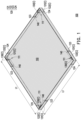
- FIG. 1 is a schematic diagram of an electronic device according to an embodiment of the invention.
- FIG. 9 is a plot diagram of frequency-VSWR (Voltage Standing Wave Ratio) of a single antenna module of the electronic device of FIG. 1 .
- the slot 121 of the embodiment may be filled with light-transmitting plastic where the metal bottom plate 110 is separated from the disconnecting part 122 , and components such as LED notification lights, etc., may be disposed in the electronic device in correspondence with the positions of the light-transmitting plastic to provide another visual effect on the appearance of the electronic device 100 .
- the material filled in the slot 121 is not limited thereto.
- the radiator 130 has a plurality of turnings (not marked) as shown in FIG. 2 , and includes a first terminal 131 and a second terminal 132 .
- the first terminal 131 is a feeding terminal 131 A
- the second terminal 132 is connected to a junction A 1 that is between the first part 122 A and the second part 122 B of the corresponding disconnecting part 122 .
- the position of the junction A 1 is on a boundary line E between the first part 122 A and the second part 122 B and intersects with the second terminal 132 , and the junction A 1 is away from the corresponding slot 121 .
- the ground terminal 111 of the metal bottom plate 110 is close to and separated from the corresponding feeding terminal 131 A.
- FIG. 3 is a schematic top view of the electronic device of FIG. 2 .
- the radiator 130 of the embodiment extends in a normal direction D 1 ( FIG. 3 ) of the metal frame 120 as shown in FIG. 3 and reaches the junction A 1 at the second terminal 132 , and the normal direction D 1 is perpendicular to the first part 122 A and the second part 122 B of the metal frame 120 .
- the second terminal 132 of the radiator 130 is connected to the junction A 1 in a direction perpendicular to the metal frame 120 on an XY plane.
- antenna characteristics of the electronic device 100 are less affected by issues of coupling spacing and overcome difficulty of assembly alignment tolerance.
- the turnings between the second section 134 and the third section 135 , and between the third section 135 and the fourth section 136 are right angles, but in other embodiments of the invention, the turnings of the radiator 130 may not be right angles, and the impedance matching of the electronic device may be adjusted by increasing a width, adding a groove, or increasing a meandering degree of the third section 135 , which is not limited by the invention.
- the metal bottom plate 110 of the embodiment is a square as shown in FIG. 1 , and a length L 1 of the metal bottom plate 110 is 200 mm.
- a length L 2 ( FIG. 2 ) from a junction of the first connecting part 123 and the first part 122 A to a vertical corner of the metal frame 120 is 35 mm, and a length L 3 ( FIG. 2 ) from the junction A 1 to the vertical corner of the metal frame 120 is 5 mm.
- a length L 4 ( FIG. 2 ) from the vertical corner of the metal frame 120 to a junction of the second part 122 B and the second connecting part 124 is 15 mm.
- FIG. 4 is a schematic cross-sectional view of the electronic device of FIG. 2 viewing along an AA section.
- a width W 1 of the slot 121 is 1.2 mm as shown in FIG. 4 , and the width W 1 may be between 1 mm and 1.5 mm, and a distance L 5 ( FIG. 4 ) between the junction A 1 and the slot 121 is 1 ⁇ 8 times of a wavelength of a frequency band of the electronic device 100 .
- a distance L 6 ( FIG. 3 and FIG. 4 ) from a junction of the first section 133 and the second section 134 to the junction A 1 is 5 mm.
- the first terminal 131 and the second terminal 132 of the radiator 130 , the first part 122 A of the corresponding disconnecting part 122 , the corresponding first connecting part 123 and the ground terminal 111 of the metal bottom plate 110 form a first antenna path R 1 as shown in FIG. 2
- the first terminal 131 and the second terminal 132 of the radiator 130 , the second part 122 B of the corresponding disconnecting part 122 , the corresponding second connecting part 124 and the ground terminal 111 of the metal bottom plate 110 form a second antenna path R 2 as shown in FIG. 2
- the first antenna path R 1 is suitable for radiating at a first frequency band
- the second antenna path R 2 is suitable for radiating at a second frequency band.
- a frequency range corresponding to the first frequency band in the embodiment is 2400-2484 MHz
- a frequency range corresponding to the second frequency band is 5150-7125 MHz
- a length of the first antenna path R 1 is between 0.5 and 0.75 times of a wavelength of the first frequency band
- a length of the second antenna path R 2 is between 0.5 and 0.75 times of a wavelength of the second frequency band.
- the frequency ranges corresponding to the first frequency band and the second frequency band are not limited thereto.
- the first antenna path R 1 radiating at the first frequency band and the second antenna path R 2 radiating at the second frequency band are further defined, such that the electronic device 100 may have good and/or omnidirectional radiation coverage.
- the metal frame 120 of the electronic device 100 is used as a part of the antenna radiator, the casing of the electronic device 100 may be designed to adopt a metal material for better looking appearance.
- the second terminal 132 of the radiator 130 is connected to the junction A 1 in a direction perpendicular to the metal frame 120 .
- the antenna characteristics of the electronic device 100 are less affected by issues of coupling spacing and overcome difficulty of assembly alignment tolerance.
- an impedance matching bandwidth of the electronic device 100 may be changed for customizations.
- FIG. 5 is a schematic top view of an electronic device according to another embodiment of the invention.
- a radiator 130 A according to another embodiment of the invention further includes a first U-shaped section 137 and a second U-shaped section 138 .
- the first U-shaped section 137 is located between the second section 134 and the third section 135
- the second U-shaped section 138 is located between the third section 135 and the fourth section 136 .
- the radiator 130 A may have more turnings among the second section 134 , the third section 135 and the fourth section 136 due to the configuration of the first U-shaped section 137 and the second U-shaped section 138 , so as to adjust the impedance matching bandwidth of the electronic device 100 for customizations.
- FIG. 6 is a schematic diagram of a layout of antenna modules on the metal bottom plate of the electronic device in FIG. 1
- FIG. 7 A to FIG. 7 C are schematic diagrams of a layout of antenna modules on a metal bottom plate of an electronic device according to another embodiment of the invention.
- antenna modules C 1 on the metal bottom plate 110 A may also be arranged in a straight line pattern at the four corners of the metal bottom plate 110 A.
- Antenna signals emitted by the antenna modules C 1 located at the four corners may take care of the coverage in four directions, 90-degree each, which achieves an effect of multi-antenna configuration.
- FIG. 8 is a schematic diagram of the electronic device of FIG. 1 applied to a robot.
- some of the antenna modules C may also be symmetrically located on a first plane 150 and a second plane 160 of the head of the robot. Namely, the antenna modules C do not need to be all arranged on the same plane, and the flexibility of the arrangement of the radiators 130 ( FIG. 1 ) in the antenna modules C may be increased to achieve customized designs.
Landscapes
- Engineering & Computer Science (AREA)
- Computer Networks & Wireless Communication (AREA)
- Details Of Aerials (AREA)
- Waveguide Aerials (AREA)
- Support Of Aerials (AREA)
Abstract
An electronic device including a metal bottom plate, a metal frame and at least one radiator is provided. The metal bottom plate includes at least one ground terminal. The metal frame includes at least one slot, at least one disconnecting part, at least one first connecting part and at least one second connecting part. The disconnecting part includes a first part and a second part. Each radiator includes a first terminal and a second terminal. The second terminal is connected to a junction between the first part and the second part. The first terminal, the second terminal, the first part, the first connecting part and the ground terminal form a first antenna path radiating at a first frequency band. The first terminal, the second terminal, the second part, the second connecting part and the ground terminal form a second antenna path radiating at a second frequency band.
Description
This application claims the priority benefit of Taiwan application serial no. 111124879, filed on Jul. 4, 2022. The entirety of the above-mentioned patent application is hereby incorporated by reference herein and made a part of this specification.
The invention relates to an electronic device, and particularly relates to an electronic device with one or more antennas.
Most electronic devices with metal casings adopt a design of an exposed antenna. However, the design of the exposed antenna is difficult to meet aesthetic demand for a metal texture. Therefore, how to configure an antenna on an electronic device with a metal casing to meet the aesthetic demand for the metal texture and have good antenna radiation performance will be a research goal in this field.
The invention is related to an electronic device, which has an aesthetic appearance with metal texture and good antenna radiation performance.
The invention provides an electronic device including a metal bottom plate, a metal frame and at least one radiator. The metal bottom plate includes at least one ground terminal. The metal frame includes at least one slot, at least one disconnecting part, at least one first connecting part and at least one second connecting part. Each slot is close to the metal bottom plate and separates the metal bottom plate from the corresponding disconnecting part. Each disconnecting part is located between the corresponding first connecting part and the corresponding second connecting part, and each disconnecting part includes a first part and a second part. The first part is close to the corresponding first connecting part, the second part is close to the corresponding second connecting part, and each first connecting part and each second connecting part are connected to the metal bottom plate. Each radiator has a plurality of turnings and includes a first terminal and a second terminal. The first terminal is a feeding terminal, and the second terminal intersects with the corresponding disconnecting part at a junction, and the junction is away from the corresponding slot. The first terminal and the second terminal of each radiator, the first part of the corresponding disconnecting part, the corresponding first connecting part and the ground terminal of the metal bottom plate form a first antenna path, and the first antenna path radiates at a first frequency band. The first terminal and the second terminal of each radiator, the second part of the corresponding disconnecting part, the corresponding second connecting part and the ground terminal of the metal bottom plate form a second antenna path, and the second antenna path radiates at a second frequency band.
In an embodiment of the invention, each radiator extends in a normal direction of the metal frame and reaches the junction at the second terminal.
In an embodiment of the invention, a length of the first antenna path is between and 0.75 times of a wavelength of the first frequency band.
In an embodiment of the invention, a length of the second antenna path is between 0.5 and 0.75 times of a wavelength of the second frequency band.
In an embodiment of the invention, a width of each slot is between 1 mm and 1.5 mm.
In an embodiment of the invention, the electronic device further includes at least one insulation bracket arranged adjacent to the at least one slot, the metal frame and the metal bottom plate, each insulation bracket includes a first surface and a second surface adjacent to each other, and each radiator includes a first section located on the first surface, and a second section, a third section and a fourth section located on the second surface, the feeding terminal is located at the first section, and the turnings are among the first section, the second section, the third section and the fourth section.
In an embodiment of the invention, the radiator further includes a first U-shaped section and a second U-shaped section, the first U-shaped section is located between the second section and the third section, and the second U-shaped section is located between the third section and the fourth section.
In an embodiment of the invention, each ground terminal is close to the corresponding feeding terminal and separated from the feeding terminal.
In an embodiment of the invention, the at least one slot includes a plurality of slots, the at least one radiator includes a plurality of radiators, positions of the radiators correspond to positions of the slots, the slots and the radiators are arranged at equal intervals on the metal frame, and the slots are located on a same plane.
In an embodiment of the invention, the at least one slot includes a plurality of slots, the at least one radiator includes a plurality of radiators, the radiators correspond to the slots, some of the slots are symmetrically located on a first plane, and some of the slots are symmetrically located on a second plane.
Based on the above description, in the electronic device of the invention, the slot separates the metal bottom plate from the corresponding disconnecting part, and the second terminal of each radiator is connected to the junction that is away from the slot and the second terminal is located between the first part and the second part of the disconnecting part. The first terminal and the second terminal of each radiator, the first part of the corresponding disconnecting part, the corresponding first connecting part and the ground terminal of the metal bottom plate form the first antenna path. The first terminal and the second terminal of each radiator, the second part of the corresponding disconnecting part, the corresponding second connecting part and the ground terminal of the metal bottom plate form the second antenna path. In this way, by using the metal frame as a part of the antenna radiator, the electronic device further defines the first antenna path that radiates at the first frequency band and the second antenna path that radiates at the second frequency band, so that the electronic device has a good performance. In addition, since the metal frame of the electronic device is used as a part of the antenna radiator, a casing of the electronic device may be designed to adopt a metal material to achieve a better looking appearance.
The accompanying drawings are included to provide a further understanding of the invention, and are incorporated in and constitute a part of this specification. The drawings illustrate embodiments of the invention and, together with the description, serve to explain the principles of the invention.
It should be noted that some components in FIG. 1 and FIG. 2 are drawn in a perspective manner to achieve the purpose of clear representation and easy explanation. In addition, FIG. 1 and FIG. 2 only show components related to the antenna, and hide other components, such as a circuit board, a battery or other electronic components.
Referring to FIG. 1 and FIG. 2 , the electronic device 100 of the embodiment includes a metal bottom plate 110, a metal frame 120 and at least one radiator 130. The metal bottom plate 110 includes at least one ground terminal 111, and the metal frame 120 includes at least one slot 121, at least one disconnecting part 122, at least one first connecting part 123 and at least one second connecting part 124. The slots 121, the disconnecting parts 122, the radiators 130 and the metal bottom plate 110 jointly form antenna modules C (FIG. 1 ).
It should be noted that, in the embodiment, the numbers of the slots 121 and the numbers of the radiators 130 are, for example, both four, and positions and the number of the radiators 130 correspond to positions and the number of the slots 121. The four slots 121 and the four radiators 130 are arranged at equal intervals at four corners of the metal frame, and the four slots 121 are all located on a same plane of the metal frame 120.
Moreover, in the embodiment, the number of the ground terminals 111, the number of the disconnecting parts 122, the number of the first connecting parts 123 and the number of the second connecting parts 124 are also four. However, in other embodiments of the invention, the number of the slots 121, the number of the radiators 130, the number of the ground terminals 111, the number of the disconnecting parts 122, the number of the first connecting parts 123, and the number of the second connecting parts 124 of the electronic device 100 may not be four, which is not limited by the invention.
It should be noted that the slot 121 of the embodiment may be filled with light-transmitting plastic where the metal bottom plate 110 is separated from the disconnecting part 122, and components such as LED notification lights, etc., may be disposed in the electronic device in correspondence with the positions of the light-transmitting plastic to provide another visual effect on the appearance of the electronic device 100. In other embodiments of the invention, the material filled in the slot 121 is not limited thereto.
In the embodiment, as shown in FIG. 2 , the radiator 130 has a plurality of turnings (not marked) as shown in FIG. 2 , and includes a first terminal 131 and a second terminal 132. The first terminal 131 is a feeding terminal 131A, and the second terminal 132 is connected to a junction A1 that is between the first part 122A and the second part 122B of the corresponding disconnecting part 122. The position of the junction A1 is on a boundary line E between the first part 122A and the second part 122B and intersects with the second terminal 132, and the junction A1 is away from the corresponding slot 121. The ground terminal 111 of the metal bottom plate 110 is close to and separated from the corresponding feeding terminal 131A.
In the embodiment, a coaxial cable utilized as a transmission line (not shown) is connected between the ground terminal 111 and the feeding terminal 131A, and an inner conductor of the coaxial transmission line as positive terminal is connected to the feeding terminal 131A, and a metallic shield as negative terminal thereof is connected to the ground terminal 111. The radiator 130 may be connected to an antenna circuit board (not shown) through the coaxial cable. However, in other embodiments of the invention, the component connecting the radiator 130 and the antenna circuit board may not be the coaxial cable, which is not limited to the present invention.
In the embodiment, the electronic device 100 further includes an insulation bracket 140. The insulation bracket 140 is disposed adjacent to the slot 121, the metal frame 120 and the metal bottom plate 110 as shown in FIG. 2 , and the insulation bracket 140 includes a first surface 141 and a second surface 142 adjacent to each other. The radiator 130 is disposed on the insulation bracket 140, and the radiator 130 extends from the first surface 141 to the second surface 142. The radiator 130 includes a first section 133 located on the first surface 141 and a second section 134, a third section 135, and a fourth section 136 located on the second surface 142. The feeding terminal 131A is located at the first segment 133, and the first segment 133 and the fourth segment 136 include the first terminal 131 and the second terminal 132, respectively, of the radiator 130 as shown in FIG. 2 .
In addition, the turnings of the radiator 130 in the embodiment are among the first section 133, the second section 134, the third section 135 and the fourth section 136. It should be noted that by adjusting the turning and a width between the second segment 134 and the third segment 135, and the turning and a width between the third segment 135 and the fourth segment 136 of the radiator 130 as shown in FIG. 3 , impedance matching of the electronic device 100 may be adjusted for customizations. In the embodiment, the turnings between the second section 134 and the third section 135, and between the third section 135 and the fourth section 136 are right angles, but in other embodiments of the invention, the turnings of the radiator 130 may not be right angles, and the impedance matching of the electronic device may be adjusted by increasing a width, adding a groove, or increasing a meandering degree of the third section 135, which is not limited by the invention.
Referring to FIG. 1 and FIG. 2 , the metal bottom plate 110 of the embodiment is a square as shown in FIG. 1 , and a length L1 of the metal bottom plate 110 is 200 mm. A length L2 (FIG. 2 ) from a junction of the first connecting part 123 and the first part 122A to a vertical corner of the metal frame 120 is 35 mm, and a length L3 (FIG. 2 ) from the junction A1 to the vertical corner of the metal frame 120 is 5 mm. A length L4 (FIG. 2 ) from the vertical corner of the metal frame 120 to a junction of the second part 122B and the second connecting part 124 is 15 mm.
In the embodiment, the first terminal 131 and the second terminal 132 of the radiator 130, the first part 122A of the corresponding disconnecting part 122, the corresponding first connecting part 123 and the ground terminal 111 of the metal bottom plate 110 form a first antenna path R1 as shown in FIG. 2 , and the first terminal 131 and the second terminal 132 of the radiator 130, the second part 122B of the corresponding disconnecting part 122, the corresponding second connecting part 124 and the ground terminal 111 of the metal bottom plate 110 form a second antenna path R2 as shown in FIG. 2 . The first antenna path R1 is suitable for radiating at a first frequency band, and the second antenna path R2 is suitable for radiating at a second frequency band.
In detail, a frequency range corresponding to the first frequency band in the embodiment is 2400-2484 MHz, and a frequency range corresponding to the second frequency band is 5150-7125 MHz. A length of the first antenna path R1 is between 0.5 and 0.75 times of a wavelength of the first frequency band, and a length of the second antenna path R2 is between 0.5 and 0.75 times of a wavelength of the second frequency band. However, in other embodiments of the invention, the frequency ranges corresponding to the first frequency band and the second frequency band are not limited thereto.
Under the above configuration of the electronic device 100 of the embodiment, by using the metal frame 120 as a part of the antenna radiator, the first antenna path R1 radiating at the first frequency band and the second antenna path R2 radiating at the second frequency band are further defined, such that the electronic device 100 may have good and/or omnidirectional radiation coverage. As the metal frame 120 of the electronic device 100 is used as a part of the antenna radiator, the casing of the electronic device 100 may be designed to adopt a metal material for better looking appearance. In addition, the second terminal 132 of the radiator 130 is connected to the junction A1 in a direction perpendicular to the metal frame 120. Compared with the antenna module designed in the manner of slot coupling in the prior art, the antenna characteristics of the electronic device 100 are less affected by issues of coupling spacing and overcome difficulty of assembly alignment tolerance. In addition, by adjusting the turnings and a line width of the radiator 130, an impedance matching bandwidth of the electronic device 100 may be changed for customizations.
Referring to FIG. 6 and FIG. 7A , compared to a metal bottom plate 110A shown in FIG. 7A with the metal bottom plate 110 shown in FIG. 6 , a difference therebetween is that antenna modules C1 on the metal bottom plate 110A may also be arranged in a straight line pattern at the four corners of the metal bottom plate 110A. Antenna signals emitted by the antenna modules C1 located at the four corners may take care of the coverage in four directions, 90-degree each, which achieves an effect of multi-antenna configuration.
Referring to FIG. 7B and FIG. 7A , compared to a metal bottom plate 110B shown in FIG. 7B with the metal bottom plate 110A shown in FIG. 7A , a difference therebetween lies in a triangular appearance of the metal bottom plate 110B, and antenna modules C2 on the metal bottom plate 110B are arranged in a straight line pattern at three corners of the metal bottom plate 110B. The antenna signals emitted by the antenna module C2 located at the three corners may take care of the coverage in three directions, 120-degree each, which has a wider coverage and may achieve the effect of multi-antenna configuration.
Referring to FIG. 7C and FIG. 7B , compared to a metal bottom plate 110C shown in FIG. 7C with the metal bottom plate 110B shown in FIG. 7B , a difference therebetween is that antenna modules C3 are evenly arranged on the metal bottom plate 110C in an arc shape. Antenna signals emitted by the antenna modules C3 may take care of the coverage in three directions, 120 degrees each, which has a wide coverage and may achieve the effect of multi-antenna configuration.
In summary, in the electronic device of the invention, by using the metal frame as a part of the antenna radiator, the electronic device further defines the first antenna path radiating at the first frequency band and the second antenna path radiating at the second frequency band, so that the electronic device may have good and/or omnidirectional radiation coverage. As the metal frame of the electronic device is used as a part of the antenna radiator, the casing of the electronic device may be designed to adopt a metal material for better looking appearance. In addition, the second terminal of the radiator of an embodiment is connected to the junction in a direction perpendicular to the metal frame. Compared with the antenna module designed in the manner of slot coupling in the prior art, the antenna characteristics of the electronic device are less affected by issues of coupling spacing and overcome difficulty of assembly alignment tolerance. In addition, by adjusting the turnings and a line width of the radiator of an embodiment, an impedance matching bandwidth of the electronic device may be changed for customizations.
Claims (10)
1. An electronic device, comprising:
a metal bottom plate, comprising at least one ground terminal;
a metal frame, comprising at least one slot, at least one disconnecting part, at least one first connecting part and at least one second connecting part, wherein each of the at least one slot is close to the metal bottom plate and separates the metal bottom plate from the corresponding disconnecting part, each of the at least one disconnecting part is located between the corresponding first connecting part and the corresponding second connecting part, and each of the at least one disconnecting part comprises a first part and a second part, the first part is close to the corresponding first connecting part, the second part is close to the corresponding second connecting part, and each of the at least one first connecting part and each of the at least one second connecting part are connected to the metal bottom plate; and
at least one radiator, each having a plurality of turnings and comprising a first terminal and a second terminal, wherein the first terminal is a feeding terminal, and the second terminal intersects with the corresponding disconnecting part at a junction, and the junction is away from the corresponding slot, wherein
the first terminal and the second terminal of each of the at least one radiator, a first part of the corresponding disconnecting part, the corresponding first connecting part and the ground terminal of the metal bottom plate form a first antenna path, and the first antenna path radiates at a first frequency band,
the first terminal and the second terminal of each of the at least one radiator, a second part of the corresponding disconnecting part, the corresponding second connecting part and the ground terminal of the metal bottom plate form a second antenna path, and the second antenna path radiates at a second frequency band.
2. The electronic device as claimed in claim 1 , wherein each of the at least one radiator extends in a normal direction of the metal frame and reaches the junction at the second terminal.
3. The electronic device as claimed in claim 1 , wherein a length of the first antenna path is between 0.5 and 0.75 times of a wavelength of the first frequency band.
4. The electronic device as claimed in claim 1 , wherein a length of the second antenna path is between 0.5 and 0.75 times of a wavelength of the second frequency band.
5. The electronic device as claimed in claim 1 , wherein a width of each of the at least one slot is between 1 mm and 1.5 mm.
6. The electronic device as claimed in claim 1 , further comprising at least one insulation bracket arranged adjacent to the at least one slot, the metal frame and the metal bottom plate, each of the at least one insulation bracket comprises a first surface and a second surface adjacent to each other, and each of the at least one radiator comprises a first section located on the first surface, and a second section, a third section and a fourth section located on the second surface, the feeding terminal is located at the first section, and the turnings are among the first section, the second section, the third section and the fourth section.
7. The electronic device as claimed in claim 6 , wherein each of the at least one radiator further comprises a first U-shaped section and a second U-shaped section, the first U-shaped section is located between the second section and the third section, and the second U-shaped section is located between the third section and the fourth section.
8. The electronic device as claimed in claim 1 , wherein each of the at least one ground terminal is close to the corresponding feeding terminal and separated from the feeding terminal.
9. The electronic device as claimed in claim 1 , wherein the at least one slot comprises a plurality of slots, the at least one radiator comprises a plurality of radiators, positions of the radiators correspond to positions of the slots, the slots and the radiators are arranged at equal intervals on the metal frame, and the slots are located on a same plane.
10. The electronic device as claimed in claim 1 , wherein the at least one slot comprises a plurality of slots, the at least one radiator comprises a plurality of radiators, the radiators correspond to the slots, some of the slots are symmetrically located on a first plane, and some of the slots are symmetrically located on a second plane.
Applications Claiming Priority (2)
| Application Number | Priority Date | Filing Date | Title |
|---|---|---|---|
| TW111124879 | 2022-07-04 | ||
| TW111124879A TWI827121B (en) | 2022-07-04 | 2022-07-04 | Electronic device |
Publications (2)
| Publication Number | Publication Date |
|---|---|
| US20240006769A1 US20240006769A1 (en) | 2024-01-04 |
| US12355165B2 true US12355165B2 (en) | 2025-07-08 |
Family
ID=89432685
Family Applications (1)
| Application Number | Title | Priority Date | Filing Date |
|---|---|---|---|
| US18/317,862 Active 2044-01-21 US12355165B2 (en) | 2022-07-04 | 2023-05-15 | Electronic device |
Country Status (2)
| Country | Link |
|---|---|
| US (1) | US12355165B2 (en) |
| TW (1) | TWI827121B (en) |
Citations (10)
| Publication number | Priority date | Publication date | Assignee | Title |
|---|---|---|---|---|
| TW200514303A (en) | 2003-10-06 | 2005-04-16 | Quanta Comp Inc | Multi-band antenna |
| CN104466390A (en) | 2014-12-09 | 2015-03-25 | 南京濠暻通讯科技有限公司 | WiFi antenna applied to metal frame mobile phone |
| CN104701619A (en) | 2014-12-31 | 2015-06-10 | 东莞劲胜精密组件股份有限公司 | Annular loop closed metal ring antenna and mobile device |
| US20180006364A1 (en) * | 2016-06-30 | 2018-01-04 | Pegatron Corporation | Wearable electronic device |
| US20180331415A1 (en) * | 2017-05-09 | 2018-11-15 | Pegatron Corporation | Electronic device and antenna structure thereof |
| US20190097308A1 (en) * | 2017-09-27 | 2019-03-28 | Chiun Mai Communication Systems, Inc. | Antenna structure and wireless communication device using same |
| US10559882B2 (en) | 2017-10-27 | 2020-02-11 | Quanta Computer Inc. | Mobile device |
| US20230046925A1 (en) * | 2021-08-10 | 2023-02-16 | Samsung Electronics Co., Ltd. | Antenna and electronic device including the same |
| US20230344140A1 (en) * | 2022-04-21 | 2023-10-26 | Samsung Electronics Co., Ltd. | Electronic device including emi absorber |
| US20230402767A1 (en) * | 2022-06-10 | 2023-12-14 | Pegatron Corporation | Electronic device |
Family Cites Families (2)
| Publication number | Priority date | Publication date | Assignee | Title |
|---|---|---|---|---|
| CN112768949A (en) * | 2020-12-11 | 2021-05-07 | 信维创科通信技术(北京)有限公司 | Hybrid antenna structure based on metal frame and electronic equipment |
| CN114447568B (en) * | 2022-02-25 | 2026-03-27 | 维沃移动通信有限公司 | Antenna components and electronic devices |
-
2022
- 2022-07-04 TW TW111124879A patent/TWI827121B/en active
-
2023
- 2023-05-15 US US18/317,862 patent/US12355165B2/en active Active
Patent Citations (10)
| Publication number | Priority date | Publication date | Assignee | Title |
|---|---|---|---|---|
| TW200514303A (en) | 2003-10-06 | 2005-04-16 | Quanta Comp Inc | Multi-band antenna |
| CN104466390A (en) | 2014-12-09 | 2015-03-25 | 南京濠暻通讯科技有限公司 | WiFi antenna applied to metal frame mobile phone |
| CN104701619A (en) | 2014-12-31 | 2015-06-10 | 东莞劲胜精密组件股份有限公司 | Annular loop closed metal ring antenna and mobile device |
| US20180006364A1 (en) * | 2016-06-30 | 2018-01-04 | Pegatron Corporation | Wearable electronic device |
| US20180331415A1 (en) * | 2017-05-09 | 2018-11-15 | Pegatron Corporation | Electronic device and antenna structure thereof |
| US20190097308A1 (en) * | 2017-09-27 | 2019-03-28 | Chiun Mai Communication Systems, Inc. | Antenna structure and wireless communication device using same |
| US10559882B2 (en) | 2017-10-27 | 2020-02-11 | Quanta Computer Inc. | Mobile device |
| US20230046925A1 (en) * | 2021-08-10 | 2023-02-16 | Samsung Electronics Co., Ltd. | Antenna and electronic device including the same |
| US20230344140A1 (en) * | 2022-04-21 | 2023-10-26 | Samsung Electronics Co., Ltd. | Electronic device including emi absorber |
| US20230402767A1 (en) * | 2022-06-10 | 2023-12-14 | Pegatron Corporation | Electronic device |
Also Published As
| Publication number | Publication date |
|---|---|
| TWI827121B (en) | 2023-12-21 |
| TW202404179A (en) | 2024-01-16 |
| US20240006769A1 (en) | 2024-01-04 |
Similar Documents
| Publication | Publication Date | Title |
|---|---|---|
| US20180294550A1 (en) | Antenna element preferably for a base station antenna | |
| US9590304B2 (en) | Broadband antenna | |
| US7561110B2 (en) | Printed antenna and a wireless network device having the antenna | |
| CN110768006A (en) | Antenna modules and electronic equipment | |
| US8502747B2 (en) | Dipole antenna assembly | |
| CN111585006B (en) | Radiation unit and array antenna | |
| US8648762B2 (en) | Loop array antenna system and electronic apparatus having the same | |
| KR20050111341A (en) | Multi-band omni directional antenna | |
| CN108631044B (en) | Antenna system and wireless network base station | |
| TW202002407A (en) | Communication device | |
| CN115207611B (en) | Antenna module and electronic device | |
| US20070024503A1 (en) | Antenna structure | |
| CN109728413B (en) | Antenna structure and terminal | |
| CN118232026B (en) | Antenna structure and electronic equipment | |
| KR20230125127A (en) | Antenna assembly and interactive tablet | |
| CN106684556A (en) | Flexible polymer antenna with multiple ground resonators | |
| TWI779577B (en) | Antenna modules and electronic equipment | |
| US12095146B2 (en) | Electronic device | |
| US20120032866A1 (en) | Broadband antenna | |
| US12355165B2 (en) | Electronic device | |
| US12407105B2 (en) | Tri-band antenna module | |
| US12191557B2 (en) | Electronic device | |
| CN107017459A (en) | Antenna assembly | |
| US7598912B2 (en) | Planar antenna structure | |
| US9722311B2 (en) | Antenna device with continuous bending structure and application system using the same |
Legal Events
| Date | Code | Title | Description |
|---|---|---|---|
| FEPP | Fee payment procedure |
Free format text: ENTITY STATUS SET TO UNDISCOUNTED (ORIGINAL EVENT CODE: BIG.); ENTITY STATUS OF PATENT OWNER: LARGE ENTITY |
|
| AS | Assignment |
Owner name: PEGATRON CORPORATION, TAIWAN Free format text: ASSIGNMENT OF ASSIGNORS INTEREST;ASSIGNORS:WU, CHIEN-YI;LIAO, CHIH-WEI;WU, CHAO-HSU;AND OTHERS;REEL/FRAME:063710/0815 Effective date: 20230512 |
|
| STPP | Information on status: patent application and granting procedure in general |
Free format text: DOCKETED NEW CASE - READY FOR EXAMINATION |
|
| STCF | Information on status: patent grant |
Free format text: PATENTED CASE |