US12350830B2 - Multi-active-axis, non-exoskeletal rehabilitation device - Google Patents
Multi-active-axis, non-exoskeletal rehabilitation device Download PDFInfo
- Publication number
- US12350830B2 US12350830B2 US16/066,189 US201616066189A US12350830B2 US 12350830 B2 US12350830 B2 US 12350830B2 US 201616066189 A US201616066189 A US 201616066189A US 12350830 B2 US12350830 B2 US 12350830B2
- Authority
- US
- United States
- Prior art keywords
- arm
- segment
- axis
- robotic device
- base
- Prior art date
- Legal status (The legal status is an assumption and is not a legal conclusion. Google has not performed a legal analysis and makes no representation as to the accuracy of the status listed.)
- Active, expires
Links
Images


Classifications
-
- A—HUMAN NECESSITIES
- A61—MEDICAL OR VETERINARY SCIENCE; HYGIENE
- A61H—PHYSICAL THERAPY APPARATUS, e.g. DEVICES FOR LOCATING OR STIMULATING REFLEX POINTS IN THE BODY; ARTIFICIAL RESPIRATION; MASSAGE; BATHING DEVICES FOR SPECIAL THERAPEUTIC OR HYGIENIC PURPOSES OR SPECIFIC PARTS OF THE BODY
- A61H1/00—Apparatus for passive exercising; Vibrating apparatus; Chiropractic devices, e.g. body impacting devices, external devices for briefly extending or aligning unbroken bones
- A61H1/02—Stretching or bending or torsioning apparatus for exercising
- A61H1/0274—Stretching or bending or torsioning apparatus for exercising for the upper limbs
-
- B—PERFORMING OPERATIONS; TRANSPORTING
- B25—HAND TOOLS; PORTABLE POWER-DRIVEN TOOLS; MANIPULATORS
- B25J—MANIPULATORS; CHAMBERS PROVIDED WITH MANIPULATION DEVICES
- B25J9/00—Programme-controlled manipulators
- B25J9/16—Programme controls
- B25J9/1612—Programme controls characterised by the hand, wrist, grip control
-
- A—HUMAN NECESSITIES
- A61—MEDICAL OR VETERINARY SCIENCE; HYGIENE
- A61H—PHYSICAL THERAPY APPARATUS, e.g. DEVICES FOR LOCATING OR STIMULATING REFLEX POINTS IN THE BODY; ARTIFICIAL RESPIRATION; MASSAGE; BATHING DEVICES FOR SPECIAL THERAPEUTIC OR HYGIENIC PURPOSES OR SPECIFIC PARTS OF THE BODY
- A61H1/00—Apparatus for passive exercising; Vibrating apparatus; Chiropractic devices, e.g. body impacting devices, external devices for briefly extending or aligning unbroken bones
-
- B—PERFORMING OPERATIONS; TRANSPORTING
- B25—HAND TOOLS; PORTABLE POWER-DRIVEN TOOLS; MANIPULATORS
- B25J—MANIPULATORS; CHAMBERS PROVIDED WITH MANIPULATION DEVICES
- B25J9/00—Programme-controlled manipulators
- B25J9/0009—Constructional details, e.g. manipulator supports, bases
-
- B—PERFORMING OPERATIONS; TRANSPORTING
- B25—HAND TOOLS; PORTABLE POWER-DRIVEN TOOLS; MANIPULATORS
- B25J—MANIPULATORS; CHAMBERS PROVIDED WITH MANIPULATION DEVICES
- B25J9/00—Programme-controlled manipulators
- B25J9/02—Programme-controlled manipulators characterised by movement of the arms, e.g. cartesian coordinate type
-
- B—PERFORMING OPERATIONS; TRANSPORTING
- B25—HAND TOOLS; PORTABLE POWER-DRIVEN TOOLS; MANIPULATORS
- B25J—MANIPULATORS; CHAMBERS PROVIDED WITH MANIPULATION DEVICES
- B25J9/00—Programme-controlled manipulators
- B25J9/16—Programme controls
- B25J9/1656—Programme controls characterised by programming, planning systems for manipulators
- B25J9/1669—Programme controls characterised by programming, planning systems for manipulators characterised by special application, e.g. multi-arm co-operation, assembly, grasping
-
- B—PERFORMING OPERATIONS; TRANSPORTING
- B25—HAND TOOLS; PORTABLE POWER-DRIVEN TOOLS; MANIPULATORS
- B25J—MANIPULATORS; CHAMBERS PROVIDED WITH MANIPULATION DEVICES
- B25J9/00—Programme-controlled manipulators
- B25J9/16—Programme controls
- B25J9/1679—Programme controls characterised by the tasks executed
- B25J9/1682—Dual arm manipulator; Coordination of several manipulators
-
- A—HUMAN NECESSITIES
- A61—MEDICAL OR VETERINARY SCIENCE; HYGIENE
- A61H—PHYSICAL THERAPY APPARATUS, e.g. DEVICES FOR LOCATING OR STIMULATING REFLEX POINTS IN THE BODY; ARTIFICIAL RESPIRATION; MASSAGE; BATHING DEVICES FOR SPECIAL THERAPEUTIC OR HYGIENIC PURPOSES OR SPECIFIC PARTS OF THE BODY
- A61H2201/00—Characteristics of apparatus not provided for in the preceding codes
- A61H2201/12—Driving means
- A61H2201/1207—Driving means with electric or magnetic drive
-
- A—HUMAN NECESSITIES
- A61—MEDICAL OR VETERINARY SCIENCE; HYGIENE
- A61H—PHYSICAL THERAPY APPARATUS, e.g. DEVICES FOR LOCATING OR STIMULATING REFLEX POINTS IN THE BODY; ARTIFICIAL RESPIRATION; MASSAGE; BATHING DEVICES FOR SPECIAL THERAPEUTIC OR HYGIENIC PURPOSES OR SPECIFIC PARTS OF THE BODY
- A61H2201/00—Characteristics of apparatus not provided for in the preceding codes
- A61H2201/16—Physical interface with patient
- A61H2201/1602—Physical interface with patient kind of interface, e.g. head rest, knee support or lumbar support
- A61H2201/1635—Hand or arm, e.g. handle
- A61H2201/1638—Holding means therefor
-
- A—HUMAN NECESSITIES
- A61—MEDICAL OR VETERINARY SCIENCE; HYGIENE
- A61H—PHYSICAL THERAPY APPARATUS, e.g. DEVICES FOR LOCATING OR STIMULATING REFLEX POINTS IN THE BODY; ARTIFICIAL RESPIRATION; MASSAGE; BATHING DEVICES FOR SPECIAL THERAPEUTIC OR HYGIENIC PURPOSES OR SPECIFIC PARTS OF THE BODY
- A61H2201/00—Characteristics of apparatus not provided for in the preceding codes
- A61H2201/16—Physical interface with patient
- A61H2201/1657—Movement of interface, i.e. force application means
- A61H2201/1659—Free spatial automatic movement of interface within a working area, e.g. Robot
-
- A—HUMAN NECESSITIES
- A61—MEDICAL OR VETERINARY SCIENCE; HYGIENE
- A61H—PHYSICAL THERAPY APPARATUS, e.g. DEVICES FOR LOCATING OR STIMULATING REFLEX POINTS IN THE BODY; ARTIFICIAL RESPIRATION; MASSAGE; BATHING DEVICES FOR SPECIAL THERAPEUTIC OR HYGIENIC PURPOSES OR SPECIFIC PARTS OF THE BODY
- A61H2203/00—Additional characteristics concerning the patient
- A61H2203/04—Position of the patient
- A61H2203/0425—Sitting on the buttocks
- A61H2203/0431—Sitting on the buttocks in 90°/90°-position, like on a chair
-
- A—HUMAN NECESSITIES
- A61—MEDICAL OR VETERINARY SCIENCE; HYGIENE
- A61H—PHYSICAL THERAPY APPARATUS, e.g. DEVICES FOR LOCATING OR STIMULATING REFLEX POINTS IN THE BODY; ARTIFICIAL RESPIRATION; MASSAGE; BATHING DEVICES FOR SPECIAL THERAPEUTIC OR HYGIENIC PURPOSES OR SPECIFIC PARTS OF THE BODY
- A61H2205/00—Devices for specific parts of the body
- A61H2205/06—Arms
Definitions
- This invention relates to devices for the rehabilitation of disabled persons with a neurological injury, such as stroke or spinal-cord injury, or otherwise impaired anatomical extremities.
- a new and exciting branch of physical and occupational therapies is therapy assisted by a computer-directed robotic arm or device (sometimes also called a “manipulator” to distinguish it from the human arm that may engage it, in certain embodiments).
- a computer-directed robotic arm or device sometimes also called a “manipulator” to distinguish it from the human arm that may engage it, in certain embodiments.
- These robotic systems leverage plasticity in the brain, which literally rewires the brain.
- dosage i.e., the amount of time engaged in therapy
- the potential benefits of using a manipulator system for tasks such as post-stroke rehabilitative therapy, which typically involves moving a patient's limb(s) through a series of repeated motions, are significant.
- therapy such as error-augmentation therapy, that simply cannot be implemented effectively by a human therapist.
- computer-directed therapy can engage the patient in games, thereby making the experience more enjoyable and encouraging longer and more intense therapy sessions, which are known to benefit patients.
- the therapist is able to work with more patients, e.g., the therapist is able to work with multiple patients simultaneously, the therapist is able to offer patients increased therapy duration (higher dosage) since the session is no longer constrained by the therapist's physical endurance or schedule, and the therapist is able to work more consecutive therapy sessions since the number of consecutive therapy sessions is no longer constrained by the therapist's physical endurance or schedule.
- DOFs degrees of freedom
- the motion of a ship at sea has six degrees of freedom (DOFs): (1) moving up and down, (2) moving left and right, (3) moving forward and backward, (4) swiveling left and right (yawing), (5) tilting forward and backward (pitching), and (6) pivoting side to side (rolling).
- low-DOF systems typically one to three DOFs
- high-DOF exoskeletal systems typically six or more DOFs
- these exoskeletons also need the ability to adjust the link lengths of the manipulator in order to accommodate the differing geometries of specific patients.
- an exoskeletal system can be thought of as an external skeleton mounted to the body, where the external skeleton has struts and joints corresponding to the bones and joints of the natural body.
- the current approaches for both categories i.e., low-DOF systems and high-DOF exoskeletal systems
- Low-DOF systems are usually less expensive than high-DOF systems, but they typically also have a smaller range of motion.
- Some low-DOF systems such as the InMotion ARMTM Therapy System of Interactive Motion Technologies of Watertown, Massachusetts, USA, or the KINARM End-Point RobotTM system of BKIN Technologies of guitarist, Ontario, Canada, are limited to only planar movements, greatly reducing the number of rehabilitation tasks that the systems can be used for.
- High-DOF exoskeletal systems such as the Armeo®Power system of Hocoma AG of Volketswil, Switzerland, the Armeo®Spring system of Hocoma AG of Volketswil, Switzerland, and the 8+2 DOF exoskeletal rehabilitation system disclosed in U.S. Pat. No. 8,317,730, are typically significantly more complex, and consequently generally more expensive, than comparable low-DOF systems. While such high-DOF exoskeletal systems usually offer greater ranges of motion than low-DOF systems, their mechanical complexity also makes them bulky, and they typically wrap around the patient's limb, making the high-DOF exoskeletal systems feel threatening and uncomfortable to patients.
- the KINARM Exoskeletal RobotTM system provides only two degrees of freedom for each limb, limiting the range of rehabilitation exercises that it can conduct. Meanwhile, by implementing an exoskeletal design, the KINARM Exoskeletal RobotTM device can provide some additional support to the patient's limb, but at the cost of significant increases in device size, cost, complexity and set-up time.
- the present invention enables a new method for bi-manual rehabilitation—a new class of rehabilitative therapy where multiple limbs, usually arms, are rehabilitated simultaneously—in which rehabilitative exercises can be conducted in three dimensions, by using two similar devices, simultaneously and in a coordinated fashion, on two different limbs of the patient.
- a non-exoskeletal rehabilitation device with as few as 2 active degrees of freedom, wherein the device is oriented and positioned such that its frame of reference (i.e., its “reference frame”) is oriented generally similarly to the reference frame of the patient, and motions of the patient's endpoint are mimicked by motions of the device's endpoint.
- its frame of reference i.e., its “reference frame”
- a non-exoskeletal rehabilitation device with as few as 2 active degrees of freedom, of which 2 degrees are linked through a cabled differential.
- a method for bi-manual rehabilitation wherein the method utilizes a pair of rehabilitation devices, wherein each rehabilitation device is designed to be capable of inducing motion in three or more degrees of freedom, is easily reconfigurable to allow both right-handed and left-handed usage, and is located relative to the patient such that two devices may be used simultaneously without interfering with each other.
- a method for operating a robotic device in association with an appendage of a user, wherein the appendage of the user has an endpoint comprising:
- a robotic device comprising:
- a robotic device comprising:
- a robotic device comprising:
- a robotic device comprising:
- a method for providing rehabilitation therapy to a user comprising:
- a method for providing rehabilitation therapy to a user comprising:
- FIGS. 1 and 2 are schematic front perspective views showing one preferred form of robotic device formed in accordance with the present invention
- FIGS. 3 and 4 are schematic top views showing the robotic device of FIGS. 1 and 2 ;
- FIGS. 6 and 7 are schematic views showing details of selected portions of the robotic device of FIGS. 1 and 2 ;
- FIGS. 8 A, 8 B and 8 C are schematic views showing the pitch-yaw configuration of the robotic device of FIGS. 1 and 2 in comparison to the roll-pitch and pitch-roll configurations of prior art devices;
- FIG. 9 is a schematic top view showing how the robotic device of the present invention may be switched from right-handed use to left-handed use;
- FIG. 10 is a schematic view showing two robotic devices being used for bi-manual rehabilitation
- FIG. 12 shows how a pair of robotic devices may communicate with an external controller, which in turn facilitates communication between the devices
- FIGS. 13 , 13 A, 14 and 15 are schematic views showing one preferred endpoint device for the robotic device of the present invention.
- FIG. 15 A is a schematic view showing the robotic device being used by a patient in a sitting position
- FIG. 15 B is a schematic view showing the robotic device being used by a patient in a standing position
- FIG. 16 is a schematic view showing another preferred endpoint device for the robotic device of the present invention.
- FIG. 18 is a schematic view showing another preferred endpoint device for the robotic device of the present invention.
- FIG. 19 is a schematic view showing details of the construction of the endpoint device of FIG. 16 ;
- FIG. 20 is a schematic view showing another preferred endpoint device for the robotic device of the present invention.
- FIGS. 21 - 26 are schematic views showing how the robotic device may be changed from left-handed use to right-handed use;
- FIGS. 27 - 29 are schematic views showing still another construction for an endpoint device.
- FIGS. 30 - 32 are schematic views showing still another construction for an endpoint device.
- Robotic device 5 generally comprises a base 100 , an inner link 105 , an outer link 110 , and a coupling element 115 for coupling outer link 110 to a patient, commonly to a limb of the patient (e.g., as shown in FIG. 1 , the patient's arm 120 ).
- robotic device 5 comprises three revolute joints, shown in FIG. 1 as joint J 1 providing pitch around an axis 125 , joint J 2 providing yaw around an axis 130 and joint J 3 providing yaw around an axis 135 .
- these joints are implemented as follows.
- Joint J 1 is a pitch joint, and consists of a segment 138 which rotates inside a generally U-shaped frame 140 .
- Joint J 2 is a yaw joint, and consists of a second segment 145 attached perpendicularly to segment 138 . This segment 145 contains a third segment 150 , which rotates inside segment 145 .
- these two joints i.e., joint J 1 and joint J 2
- Joint J 3 is also a yaw joint, and is separated from joint J 2 by inner link 105 .
- a cable transmission connects the motor that actuates joint J 3 (and which is located coaxially to the axis 130 of joint J 2 , as will hereinafter be discussed) to the output of joint J 3 ; this cable transmission runs through inner link 105 .
- this cable transmission runs through inner link 105 .
- different endpoint attachments may be provided at the location of the coupling element 115 , to permit different degrees of control over the patient's limb orientation, or to provide additional therapeutic modalities.
- different endpoint attachments may comprise a single-DOF endpoint attachment for performing linear rehabilitation exercises; or a three-DOF endpoint attachment to enable more complex motions, by enabling control over the orientation of the patient's limb; or an actively-controlled multi-DOF endpoint attachment.
- the preferred embodiment of the robotic device consists of the following four kinematic frames (i.e., the kinematic frames of reference for various points on the robotic device):
- joints J 1 and J 2 are implemented through the use of a cabled differential transmission, designed similarly to that disclosed in U.S. Pat. No. 4,903,536, issued Feb. 27, 1990 to Massachusetts Institute of Technology and J. Kenneth Salisbury, Jr. et al. for COMPACT CABLE TRANSMISSION WITH CABLE DIFFERENTIAL, which patent is hereby incorporated herein by reference.
- a cabled differential is a novel implementation of a differential transmission, in which two input pulleys (e.g., pulleys 505 in the robotic device 5 shown in FIG. 6 ) with a common axis of rotation are coupled to a common output pulley, (e.g., pulley 540 in the robotic device 5 shown in FIGS. 1 and 6 ) which is affixed to a spider or carrier (e.g., carrier 541 in the robotic device 5 shown in FIGS. 1 and 6 ).
- This carrier is able to rotate about the common axis of rotation of the two input pulleys independently of those pulleys.
- the common output pulley meanwhile, is able to rotate about an axis perpendicular to, and coincident with, the common axis of rotation of the two input pulleys.
- the two input pulleys are coupled to the output pulley such that a differential relationship is established between the three, wherein the rotation of the output pulley (e.g., pulley 540 in robotic device 5 shown in FIGS. 1 and 6 ) is proportional to the sum of the rotations of the two input pulleys (e.g., pulleys 505 in robotic device 5 shown in FIGS. 1 and 6 ), and the rotation of the carrier (e.g., carrier 541 in robotic device 5 shown in FIGS.
- the rotation of the carrier of the differential is used to produce motion of the system about one axis of rotation (in the preferred embodiment, about axis 125 of joint J 1 ), and the rotation of the output of the differential transmission (i.e., the rotation of output pulley 540 ) is used to produce motion of the system about a second axis of rotation (in the preferred embodiment, about axis 130 of joint J 2 ).
- this cabled differential transmission consists of two motors 500 , input pulleys 505 , output pulley 540 , etc., as hereinafter discussed.
- the cabled transmission is a novel implementation of a differential transmission, wherein two input pulleys (e.g., pulleys 505 in robotic device 5 shown in FIG. 6 ) are connected to a third common output pulley (e.g., pulley 540 in robotic device 5 shown in FIG. 6 ) such that the rotation of the output pulley is proportional to the sum of the rotations of the two input pulleys, and the rotation of the differential carrier (e.g., carrier 541 in robotic device 5 shown in FIG. 6 ) is proportional to the difference of the rotations of the two input pulleys.
- this transmission consists of two motors 500 , two input pulleys 505 , output pulley 540 , etc., as hereinafter discussed.
- the cabled differential transmission preferably comprises two motors 500 which are affixed to the ground kinematic frame (e.g., base 502 ), which are coupled to input pulleys 505 through lengths of cable 571 and 572 —commonly wire rope, but alternatively natural fiber, synthetic fiber, or some other construction generally recognized as a form of cable—that are attached to the pinions 510 of motors 500 , wrapped in opposite directions but with the same chirality about pinions 510 , and terminated on the outer diameters 515 of input pulleys 505 .
- the ground kinematic frame e.g., base 502
- input pulleys 505 through lengths of cable 571 and 572 —commonly wire rope, but alternatively natural fiber, synthetic fiber, or some other construction generally recognized as a form of cable—that are attached to the pinions 510 of motors 500 , wrapped in opposite directions but with the same chirality about pinions 510 , and terminated on the outer diameters 5
- These input pulleys 505 rotate about axis 125 of joint J 1 , but their rotation may produce rotation of the device about axis 125 of joint J 1 , axis 130 of joint J 2 , or both axes simultaneously, due to the properties of the cable differential; furthermore, these input pulleys 505 are fixed to neither the aforementioned joint J 1 kinematic frame nor the aforementioned joint J 2 kinematic frame. As per U.S. Pat. No. 4,903,536, these input pulleys 505 include both large outer diameters 515 , as well as a series of substantially smaller stepped outer diameters 520 , 525 , 530 and 535 .
- output pulley 540 which comprises a series of stepped outer diameters 545 , 550 , 555 , and 560 , which are substantially larger than the steps 520 , 525 , 530 and 535 they are coupled to on input pulleys 505 .
- This output pulley 540 rotates about axis 130 of joint J 2 , and is fixed to the joint J 2 kinematic frame. It has been found that it can be useful to make the range of motion of joint J 2 symmetric about a plane coincident with joint J 2 and perpendicular to joint J 1 , as this facilitates switching the device's chirality as described below.
- a transmission ratio of 8.51:1 is implemented between motor pinions 510 and input pulleys 505
- a transmission ratio of 1.79:1 is implemented between input pulleys 505 and output pulley 540 , generating a maximum transmission ratio between motor pinions 510 and output pulley 540 of 15.26:1.
- distal to output pulley 540 is another cable transmission, comprising a motor 565 , coupled from its motor pinion 570 through cables 576 , 577 to intermediate pulleys 575 , which are in turn coupled through cables 578 , 579 to an output pulley 580 .
- These transmission cables are contained inside inner link 105 , which is fixed to the aforementioned joint J 2 kinematic frame. In this additional cable transmission, no differential element is implemented. In keeping with the cable transmission design taught in U.S. Pat. No.
- the first stage of the cable transmission between motor pinion 570 and intermediate pulleys 575 is designed to be a high-speed, lower-tension transmission stage that traverses a greater distance; while the second stage of the cable transmission, between intermediate pulleys 575 and output pulley 580 , is designed to be a low-speed, higher-tension transmission stage that traverses a very short distance.
- intermediate pulleys 575 , output pulley 580 and the joint axis 135 of joint J 3 are substantially distal to motor 565 , a design which is accomplished by implementing a long cable run between motor pinion 570 and intermediate pulleys 575 .
- this design has the benefit of moving the mass of motor 565 toward base 502 of robotic device 5 , reducing the inertia of the system.
- the motor's mass is positioned coaxial to axis 130 of joint J 2 , and as close as possible to axis 125 of joint J 1 , thereby reducing inertia about both axes.
- This design is particularly valuable in the preferred implementation shown, since the mass of motor 565 is moved close to both axis 130 of joint J 2 and axis 125 of joint J 1 , thereby reducing inertia about both axes.
- a transmission ratio of 1.89:1 is preferably implemented between motor pinion 570 and intermediate pulleys 575 , and a transmission ratio of 5.06:1 is preferably implemented between intermediate pulleys 575 and output pulley 580 , yielding a maximum transmission ratio between motor pinion 575 and output pulley 580 of 9.55:1.
- Outer link 110 is connected to output pulley 580 ( FIGS. 6 and 7 ) of joint J 3 by a mechanism 590 that allows the position of outer link 110 to be adjusted relative to output pulley 580 of joint J 3 .
- Mechanism 590 FIG. 7 , which in a preferred embodiment allows the position of outer link 110 to be moved by some number of degrees (e.g., 172.5 degrees) about axis 135 of joint J 3 relative to output pulley 580 of joint J 3 , facilitates reversing the chirality of the robotic device, the importance and method of which is described herein.
- mechanism 590 is implemented by means of clamping two tabs 591 against a central hub 592 (which is shown in FIG. 7 in cutaway) by means of a toggle lock 593 (e.g., like those commonly found on the forks of bicycles).
- the contacting faces of tabs 591 and central hub 592 are tapered as shown in FIG. 7 , to both locate the parts in directions transverse to the direction of force application, and to increase the amount of torque that the clamped parts can resist. It has been found that it is important to ensure that the taper (at the contacting faces of tabs 591 and central hub 592 ) is a non-locking type, so that the system does not jam.
- Mechanism 590 allows outer link 110 to be flipped across a plane coincident to axis 135 of joint J 3 , rather than rotated around axis 135 of joint J 3 . While this initially seems like a minor distinction, when implemented with certain types of endpoint attachments, utilizing a mechanism that flips, rather than rotates, can significantly reduce the time required to reverse the chirality of the robotic device.
- utilizing a mechanism that flips, rather than rotates can significantly reduce the time required to reverse the chirality of the robotic device.
- these components may include limit switches, magnets, latches, etc. of the sort well known to a person skilled in the art of robotic arms.
- robotic device 5 is a non-exoskeletal rehabilitation device.
- Exoskeletal rehabilitation devices are generally understood as those having some or all of the following characteristics:
- robotic device 5 is designed such that its motions mimic those of the patient, in that a given motion of the patient's endpoint in reference frame 160 of the patient will be matched by a generally similar motion of the device's endpoint in reference frame 170 of robotic device 5 .
- This relationship is important to the definition of many of the innovative aspects of robotic device 5 , as shown below.
- the “forward” vector 162 is likewise defined in the commonly accepted “forward” direction (i.e., in front of the patient). More precisely, it is treated as a “Y” vector in a right-handed coordinate system, and is defined as the component of the vector pointing from the origin to the center of the limb's workspace which is perpendicular to the “up” vector. Finally, the “right” vector 163 points to the right of the patient. Rigorously defined, it is treated as an “X” vector in a right-handed coordinate system, and is consequently defined by the other two vectors.
- a reference frame 160 is defined for the patient which is located and oriented entirely by constant physical characteristics and features. While this coordinate frame definition has been executed in FIGS. 2 and 3 for a patient's arm, this definition method can easily be extended to other limbs, such as a leg.
- a similar reference frame is defined for the robotic device.
- the origin is placed at the centroid of the base of robotic device 5 , which must also be fixed in space.
- the “forward” vector 172 is defined as the component of the vector pointing from the origin to the geometric centroid of the device's workspace.
- the “up” vector 171 and the “right” vector 173 may be defined in arbitrary directions, so long as they meet the following conditions:
- the aforementioned condition “4) cannot be satisfied because the device's “forward” vector already points in the generally accepted “up” direction; consequently, the “up” vector may be defined arbitrarily subject to the three previous conditions. This case is further detailed below.
- the robotic device and the patient operate with their reference frames (as defined above) oriented generally similarly, i.e., “up”, “right” and “forward” correspond to generally the same directions for both the patient and the robotic device, with the misalignment between any pair of directions in the PRF (patient reference frame) and DRF (device reference frame), respectively, preferably no greater than 60 degrees (i.e., the “forward” direction in the DRF will deviate no more than 60 degrees from the “forward” direction in the PRF), and preferably no greater than 45 degrees.
- a non-exoskeletal device in which the device reference frame and the patient reference frame are generally oriented similarly in this way has not been created. Devices available today are oriented relative to the patient in a number of different ways, including the following:
- the robotic device of the present invention is the first non-exoskeletal device which is designed to operate with its reference frame 170 oriented generally similarly to the reference frame 160 of the patient.
- This innovation allows the robotic device to leverage advantages that are otherwise limited to exoskeletal devices, including:
- robotic device 5 generally mimics the movements of the patient's limb, in that the endpoint of the device tracks the patient's limb, and a given motion in reference frame 160 of the patient produces motion in a generally similar direction in the device's reference frame 170 .
- the device's links will generally move to the right in the device's reference frame 170 , as shown in FIG. 4 .
- the individual links and joints of the robotic device do not necessarily mimic the motions of individual segments or joints of the patient's limb, even though the endpoint of the robotic device does track the patient's endpoint. As shown in FIG.
- robotic device 5 avoids many of the weaknesses inherent in exoskeletal devices, particularly the bulk, complexity, cost and set-up time associated with directly replicating the kinematics of a limb.
- robotic device 5 Because of the need for this distinction between the robotic device of the present invention and exoskeletal devices (i.e., that a relationship cannot easily be defined between the patient's limb and the links of robotic device 5 ), it is necessary to define the relationship between the robotic device and the patient as a function of the bases, endpoints and orientations of the robotic device and the patient.
- the previous statement that “robotic device 5 is designed such that its motions mimic those of the patient, in that a given motion of the patient's endpoint in reference frame 160 of the patient will be matched by a generally similar motion of the device's endpoint in reference frame 170 of robotic device 5 ” is satisfied only when robotic device 5 is oriented relative to the patient as described herein.
- the “forward” direction can be defined as the general direction from the base of the patient's arm undergoing rehabilitation, along the patient's limb, towards the patient's endpoint when it is at the position most commonly accessed during use of the device.
- the “forward” direction can be defined as the general direction from the base of the device, along the device's links and joints, towards the device's endpoint when it is at the position most commonly accessed during use of the device.
- the device and the user can be said to be generally similarly oriented.
- FIGS. 3 and 4 One preferred embodiment of the present invention is shown in FIGS. 3 and 4 , where robotic device 5 is positioned to the side of, and slightly behind, the patient (in this case, with axis 125 of joint J 1 behind, or coincident to, the patient's coronal plane).
- reference frame 170 of robotic device 5 and reference frame 160 of the patient are oriented generally similarly to one another, as described above.
- Robotic device 5 is kept out of the patient's workspace and line of sight, making it both physically and visually unobtrusive.
- the workspaces of the robotic device and the patient overlap to a high degree.
- the range of motion allowed by this positioning is still quite large, as shown in FIG. 4 , and approaches or exceeds that allowed by high-DOF exoskeletal systems.
- robotic device 5 is positioned differently relative to the patient which may be better suited to other applications, such as use as a haptic input/control device, or other rehabilitative activities.
- robotic device 5 may prove optimal to place the robotic device slightly in front of the patient.
- FIGS. 5 A, 5 B and 5 C several novel implementations of the system are shown wherein the device's links 105 , 110 are ordered in different directions to facilitate different activities.
- FIG. 5 A shows a configuration referred to as the “stacked-down” configuration, in which outer link 110 of robotic device 5 is attached to the underside of inner link 105 of robotic device 5 , allowing the device to reach from above the patient, downwards, to their limb (attached via coupling element 115 ).
- FIG. 5 A shows a configuration referred to as the “stacked-down” configuration, in which outer link 110 of robotic device 5 is attached to the underside of inner link 105 of robotic device 5 , allowing the device to reach from above the patient, downwards, to their limb (attached via coupling element 115 ).
- FIG. 5 A shows a configuration referred to as the “stacked-down” configuration, in which outer link 110 of robotic device 5 is attached to the underside of inner link 105 of robotic device 5 , allowing the device to reach from above
- FIG. 5 C shows a configuration referred to as the “stacked-up” configuration, in which outer link 110 of robotic device 5 is attached to the top side of inner link 105 of robotic device 5 , allowing the device to reach from below the patient, upwards, to their limb (attached via coupling element 115 ).
- Both implementations may prove optimal in different situations.
- the “stacked-down” variant is less likely to interfere with the patient's arm during rehabilitation activity because of its position above the patient's workspace, and may prove more useful for high-functioning rehabilitation patients who require expanded workspace.
- the “stacked-up” variant is better able to support a patient's arm, and is less likely to interfere with the patient's visual workspace; it is better suited for low-functioning patients.
- 5 B shows a configuration referred to as the “stacked-flat” configuration, in which outer link 110 of robotic device 5 is attached to the bottom side of inner link 105 of robotic device 5 , and coupling element 115 is attached to the top side of outer link 110 , allowing the device to reach the patient so that the forearm of the patient is approximately flat with inner link 105 .
- FIG. 6 illustrates an important aspect of the present invention, i.e., the use of a cabled differential (see, for example, U.S. Pat. No. 4,903,536) in a rehabilitation device.
- the preferred embodiment of robotic device 5 comprises three revolute joints J 1 , J 2 and J 3 , implemented in a pitch-yaw-yaw configuration ( FIG. 1 ), with the first two joints (i.e., J 1 and J 2 ) linked in a cabled differential as shown in FIG. 6 .
- the use of a cabled differential allows a motor that would normally be mounted on a higher-level kinematic frame to be moved down to a lower-level frame.
- FIG. 6 illustrates an important aspect of the present invention, i.e., the use of a cabled differential (see, for example, U.S. Pat. No. 4,903,536) in a rehabilitation device.
- the preferred embodiment of robotic device 5 comprises three revolute joints J 1 , J 2 and J 3 , implemented
- motors 500 that cause rotation about joint J 1 and joint J 2 are moved from the aforementioned joint J 1 kinematic frame (which rotates about axis 125 of joint J 1 ) down to the aforementioned ground kinematic frame (the ground frame; co-located with base 100 in FIG. 1 ).
- this is implemented in the preferred embodiment at the base of the robotic device, the principle behind this design is valid anywhere along a device's kinematic chain.
- This configuration also allows the exclusive use of rotary joints (instead of prismatic joints), which greatly simplifies the design of the device. Lower inertia also improves the safety of the device by lowering the momentum of the device.
- this innovation also maximizes usability by allowing the visual bulk of the device to be shifted away from the patient's line of sight towards the base of the device. While this concept is executed as part of a rehabilitation device with three degrees of freedom in the preferred embodiment, it is clearly applicable to other rehabilitation devices with as few as two degrees of freedom.
- the gravity compensation means of the present invention includes various apparatus/algorithms/procedures which involve:
- Robotic device 5 is configured so that it has the ability to easily flip from a right-hand to a left-hand configuration, e.g., using a cam-latch (similar to those found on front bicycle wheels) such as the aforementioned cam-latch 594 which allows outer link 110 of a given endpoint device to be quickly and easily attached to/detached from the remainder of robotic device 5 .
- robotic device 5 has knowledge of the “handedness” of a given endpoint device due to the aforementioned automatic endpoint sensing switches. This allows robotic device 5 to automatically alter the software in its onboard controller 596 to account for the different kinematics of different endpoint devices.
- the various endpoint devices have been designed to accommodate this flipping and can be used in both right-hand and left-hand configurations.
- the flips are performed in the same order, but reversing the directions of the flips.
- Pronation/supination is the twist/rotation of the wrist about the longitudinal axis of the forearm.
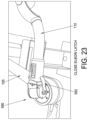
- a pair of Kaydon-style ring bearings 905 are used to support cradle 805 above a cradle support 910 (not shown in FIGS. 27 - 29 ), which is in turn connected to outer link 110 (not shown in FIGS. 27 - 29 ).
- Kaydon-style ring bearings 905 are large enough (e.g., 150 mm) to accommodate pronation/supination of the forearm/wrist of the 95th-percentile male hand and arm while the user's forearm is strapped to cradle 805 .
- An encoder 915 is used to track user position and communicate the same to onboard controller 956 of robotic device 5 .
- a 4-bar linkage 920 is used to support cradle 805 above a cradle support 925 , with cradle support 925 being connected to connector 815 (not shown in FIGS. 30 - 32 ), which is in turn connected to outer link 110 (not shown in FIGS. 30 - 32 ).
- Cradle support 925 and linkage 920 are located beneath the cradle, completely hidden from the view of the user. This approach enables about 90 degrees of wrist pronation/supination and lowers fabrication costs by avoiding the use of ring bearings. Also, with this approach, the patient or user can more easily get into and out of the endpoint device. Furthermore, there is no limitation on the size of the user's hand and forearm as there might be the case with the ring bearings.
- An encoder 930 is used to track user position and communicate the same to onboard controller 956 of robotic device 5 .
- the robotic device is configured to provide game-based rehabilitation.
- the patient views a two-dimensional (2D) or three-dimensional (3D) scene using a computer screen, a projector, glasses, goggles, or similar means.
- the 2D or 3D scene depicts a game which the patient “plays” by moving their limb (which is connected to the robotic device) so as to cause corresponding movement of a virtual object (or virtual character) within the 2D or 3D scene.
- the patient endeavors to appropriately move their limb so as to cause appropriate movement of the virtual object (or virtual character) within the 2D or 3D scene of the game, the patient “effortlessly” participates in the therapy process.
- This form of the invention is a powerful tool, since it promotes increased engagement of the patient in the therapy process, and thereby yields higher “dosages” of the physical therapy or occupational therapy, which is known to be an essential element in successful recovery from stroke and many other injuries and diseases.
- the 2D or 3D scene may take another non-game form, i.e., the 2D or 3D scene may be a non-game graphical or textual display, with the patient endeavoring to appropriately move their limb (which is connected to the robotic device) so as to cause appropriate movement of a virtual object within a graphical or textual display.
- This non-game approach while less engaging for the patient than the game-based physical therapy or occupational therapy described above, is nonetheless capable of providing a valuable assessment measure.
- the patient is essentially endeavoring to appropriately move their limb (which is connected to the endpoint of the robotic device) so as to cause corresponding appropriate movement of a virtual object (or virtual character) on a computer screen, projector, glasses, goggles or similar means.
- ABT Activity Based Training
- the robotic device is also configured so that activity-based therapy may be provided without requiring physical intervention from the therapist, as it may be sufficient for the robotic device to simply suspend some fraction of the weight of the patient's limb, thereby allowing the patient to succeed at a given activity.
- the robotic device may also be provided with pre-conceived therapy modalities that go beyond just simply limb suspension, such as a generalized pre-defined path along which the patient movement is constrained, so that the robotic device acts in the sense of a guide.
- the present invention is generally discussed in the context of its application for a rehabilitation device. However, it will be appreciated that the present invention may also be utilized in other applications, such as applications requiring high-fidelity force feedback.
- these applications may include use as an input/haptic feedback device for electronic games, as a controller for other mechanical devices such as industrial robotic arms and/or construction machines, or as a device for sensing position, i.e., as a digitizer or coordinate-measuring device.
Landscapes
- Engineering & Computer Science (AREA)
- Robotics (AREA)
- Mechanical Engineering (AREA)
- Health & Medical Sciences (AREA)
- General Health & Medical Sciences (AREA)
- Life Sciences & Earth Sciences (AREA)
- Physical Education & Sports Medicine (AREA)
- Rehabilitation Therapy (AREA)
- Pain & Pain Management (AREA)
- Animal Behavior & Ethology (AREA)
- Epidemiology (AREA)
- Public Health (AREA)
- Veterinary Medicine (AREA)
- Orthopedic Medicine & Surgery (AREA)
- Rehabilitation Tools (AREA)
- Manipulator (AREA)
Abstract
Description
-
- (i) is a continuation-in-part of pending prior U.S. patent application Ser. No. 14/500,810, filed Sep. 29, 2014 by Barrett Technology, Inc. and William T. Townsend et al. for MULTI-ACTIVE-AXIS, NON-EXOSKELETAL REHABILITATION DEVICE, which patent application claims benefit of prior U.S. Provisional Patent Application Ser. No. 61/883,367, filed Sep. 27, 2013 by Barrett Technology, Inc. and William T. Townsend et al. for THREE-ACTIVE-AXIS REHABILITATION DEVICE;
- (ii) claims benefit of pending prior U.S. Provisional Patent Application Ser. No. 62/235,276, filed Sep. 30, 2015 by Barrett Technology, Inc. and Alexander Jenko et al. for MULTI-ACTIVE-AXIS, NON-EXOSKELETAL REHABILITATION DEVICE; and
- (iii) claims benefit of pending prior U.S. Provisional Patent Application Ser. No. 62/340,832, filed May 24, 2016 by Barrett Technology, LLC and William T. Townsend et al. for MULTI-ACTIVE-AXIS, NON-EXOSKELETAL REHABILITATION DEVICE.
-
- a base; and
- a robotic arm attached to the base and having an endpoint, the robotic arm having at least two active degrees of freedom relative to the base and being configured so that when the base is appropriately positioned relative to a user, the reference frame of the robotic device is oriented generally similarly to the reference frame of the user and motions of the endpoint of the appendage of the user are mimicked by motions of the endpoint of the robotic arm.
-
- providing a robotic device comprising:
- a base; and
- a robotic arm attached to the base and having an endpoint, the robotic arm having at least two active degrees of freedom relative to the base and being configured so that when the base is appropriately positioned relative to a user, the reference frame of the robotic device is oriented generally similarly to the reference frame of the user and motions of the endpoint of the appendage of the user are mimicked by motions of the endpoint of the robotic arm;
- positioning the base relative to the user so that the reference frame of the robotic device is oriented generally similarly to the reference frame of the user, and attaching the appendage of the user to the robotic arm; and
- moving at least one of the endpoint of the appendage of the user and the endpoint of the robotic arm.
- providing a robotic device comprising:
-
- a base;
- an arm having a first end and a second end, the first end of the arm being mounted to the base and the second end of the arm being configured to receive an endpoint device;
- an endpoint device configured to be mounted to the second end of the arm and being configured for engagement by a limb of a user; and
- a controller mounted to at least one of the base and the arm for controlling operation of the arm;
- wherein the endpoint device comprises a user-presence sensing unit for detecting engagement of the endpoint device by a limb of a user and advising the controller of the same.
-
- a base;
- an arm having a first end and a second end, the first end of the arm being mounted to the base and the second end of the arm being configured to receive an endpoint device;
- an endpoint device configured to be mounted to the second end of the arm and being configured for engagement by a limb of a user; and
- a controller mounted to at least one of the base and the arm for controlling operation of the arm;
- wherein the endpoint device is mountable to the second end of the arm using a modular connection which provides mechanical mounting of the endpoint device to the second end of the arm and electrical communication between the endpoint device and the arm.
-
- a base;
- an arm having a first end and a second end, the first end of the arm being mounted to the base and the second end of the arm being configured to receive an endpoint device;
- an endpoint device configured to be mounted to the second end of the arm and being configured for engagement by a limb of a user; and
- a controller mounted to at least one of the base and the arm for controlling operation of the arm;
- wherein the endpoint device is adjustable relative to the second end of the arm along a pitch axis and a yaw axis.
-
- a base;
- an arm having a first end and a second end, the first end of the arm being mounted to the base and the second end of the arm being configured to receive an endpoint device;
- an endpoint device configured to be mounted to the second end of the arm and being configured for engagement by a limb of a user; and
- a controller mounted to at least one of the base and the arm for controlling operation of the arm;
- wherein the controller is configured to compensate for the effects of gravity when the endpoint device is engaged by a limb of a user.
-
- providing a robotic device comprising:
- a base;
- an arm having a first end and a second end, the first end of the arm being mounted to the base and the second end of the arm being configured to receive an endpoint device;
- an endpoint device configured to be mounted to the second end of the arm and being configured for engagement by a limb of a user; and
- a controller mounted to at least one of the base and the arm for controlling operation of the arm;
- wherein the endpoint device comprises a user-presence sensing unit for detecting engagement of the endpoint device by a limb of a user and advising the controller of the same; and
- operating the robotic device.
- providing a robotic device comprising:
-
- providing a robotic device comprising:
- a base;
- an arm having a first end and a second end, the first end of the arm being mounted to the base and the second end of the arm being configured to receive an endpoint device;
- an endpoint device configured to be mounted to the second end of the arm and being configured for engagement by a limb of a user; and
- a controller mounted to at least one of the base and the arm for controlling operation of the arm;
- wherein the endpoint device is mountable to the second end of the arm using a modular connection which provides mechanical mounting of the endpoint device to the second end of the arm and electrical communication between the endpoint device and the arm; and
- operating the robotic device.
- providing a robotic device comprising:
-
- providing a robotic device comprising:
- a base;
- an arm having a first end and a second end, the first end of the arm being mounted to the base and the second end of the arm being configured to receive an endpoint device;
- an endpoint device configured to be mounted to the second end of the arm and being configured for engagement by a limb of a user; and
- a controller mounted to at least one of the base and the arm for controlling operation of the arm;
- wherein the endpoint device is adjustable relative to the second end of the arm along a pitch axis and a yaw axis; and
- operating the robotic device.
- providing a robotic device comprising:
-
- providing a robotic device comprising:
- a base;
- an arm having a first end and a second end, the first end of the arm being mounted to the base and the second end of the arm being configured to receive an endpoint device;
- an endpoint device configured to be mounted to the second end of the arm and being configured for engagement by a limb of a user; and
- a controller mounted to at least one of the base and the arm for controlling operation of the arm;
- wherein the controller is configured to compensate for the effects of gravity when the endpoint device is engaged by a limb of a user; and
- operating the robotic device.
- providing a robotic device comprising:
-
- devices with alternative kinematics—for example, three joints in a yaw-pitch-yaw arrangement (as opposed to the pitch-yaw-yaw arrangement of
FIG. 1 ); - devices using other types of joints, such as prismatic joints (i.e., slider joints); and
- devices that implement other drive technologies, such as gear drivetrains, belts, hydraulic drives, etc.
- devices with alternative kinematics—for example, three joints in a yaw-pitch-yaw arrangement (as opposed to the pitch-yaw-yaw arrangement of
-
- 1) The ground kinematic frame, consisting of all components that are generally static when the device is in use;
- 2) The joint J1 kinematic frame, consisting of all non-transmission components that rotate exclusively about
axis 125 of joint J1; - 3) The joint J2 kinematic frame, consisting of all non-transmission components that may rotate exclusively about
axis 125 of joint J1 andaxis 130 of joint J2; and - 4) The joint J3 kinematic frame, consisting of all non-transmission components that may rotate about
axis 125 of joint J1,axis 130 of joint J2 andaxis 135 of joint J3.
In this definition of kinematic frames, transmission components are excluded to simplify definition: a pulley within a transmission may be located away from a given joint, but rotate with that joint. Similarly, some pulleys in the system may be caused to rotate by the motion of more than one axis—for example, when they are part of a cabled differential, such as is employed in the preferred form of the present invention.
-
- device link lengths;
- device component inertias and moments about axes;
- the intended position of the device relative to the patient;
- motor instantaneous peak and sustained torque limits;
- motor controller output current capacity, and motor current capacity;
- desired ability of device to overpower patient/be overpowered by patient; and
- expected peak output force of patient.
-
- push/pull away from/towards patient's body: 45 N
- up/down in front of patient: 15 N
- left/right laterally in front of patient: 17 N
It should be noted that generous factors of safety have been applied to these estimates.
-
- joint axes that pierce/are coaxial to the patient's limb joint axes, typically with each patient joint matched to at least one device joint; and
- device components that capture each of the patient's limbs that are being rehabilitated, typically firmly constraining each limb segment to a corresponding segment of the arm of the robotic device.
-
- 1) they are mutually perpendicular;
- 2) they are both perpendicular to “forward”
vector 172; - 3) they meet the definition of a right-handed coordinate system wherein “up”
vector 171 is treated as a Z vector, “right”vector 173 is treated as an X vector, and “forward”vector 172 is treated as a Y vector; and - 4) preferably, but not necessarily, “up”
vector 171 is oriented as closely as possible to the commonly accepted “up” direction (i.e., against the direction of gravity).
-
- The DRF may be rotated 180° around the “up” axis relative to the PRF so that the device “faces” towards the patient, or rotated 90° around the “up” axis so that the device “faces” perpendicular to the patient: for example, in the InMotion ARM™ system of Interactive Motion Technologies of Watertown, Mass., USA; the HapticMaster™ haptic system of Moog Incorporated of East Aurora, New York, USA; the DeXtreme™ arm of BioXtreme of Rehovot, Israel; or the KINARM End-Point Robot™ of BKIN Technologies of Kingston, Ontario, Canada. In the case of the DeXtreme™ arm, for example, the device is designed to be used while situated in front of the patient. Its workspace, which is generally shaped like an acute segment of a right cylinder radiating from the device's base, likewise faces toward the patient. When a coordinate reference frame is generated for the device's workspace as outlined above, the “forward” direction for the device—which points from the centroid of the base of the device to the centroid of the device's workspace—will be found to point toward the patient. Consequently, the device reference frame is not oriented similarly to the patient reference frame.
- Alternatively, the DRF may be rotated 90° about the “right” axis relative to the PRF such that the device's “forward” axis is parallel to the patient's “up” axis; or other combinations. One example is the ReoGO® arm rehabilitation system of Motorika Medical Ltd of Mount Laurel, New Jersey, USA, where the device's base sits underneath the patient's arm undergoing rehabilitation, and its primary link extends up to the patient's arm. Its workspace is generally conical, with the tip of the cone located at the centroid of the base of the device. When a coordinate reference frame is generated for the device as outlined above, the “forward” vector of the device reference frame will be found to have the same direction as the “up” vector in the patient reference frame. Consequently, the device reference frame is not oriented similarly to that of the patient reference frame.
- Finally, devices like the ArmAssist™ device of Tecnalia® of Donostia-San Sebastián, Spain may not have a definable DRF. The ArmAssist™ device is a small mobile platform which is designed to sit on a tabletop in front of the patient. The patient's arm is attached to the device, which then moves around the tabletop to provide rehabilitative therapy. Since the ArmAssist™ device is fully mobile, a fixed origin cannot be defined for it as per the method outlined above, and it is not relevant to this discussion.
-
- Reduced interference with the patient's line-of-sight or body, since the robotic device does not need to sit in front of/to the side of the patient.
- More optimal position-torque relationships between patient and device, since the moment arms between the device and patient endpoints and their joints are directly proportional to one another, rather than inversely proportional to one another as in other devices. For example, when the device's links are extended, the patient's limb undergoing rehabilitation will generally be extended as well. While the device is not able to exert as much force at its endpoint as it can when the endpoint is closer to the device's joints, the patient's force output capacity will likewise be reduced. Similarly, when the patient's limb is contracted and the force output is maximized, the device's endpoint will be closer to its joints, and its endpoint output force capacity will also be maximized.
- Better workspace overlap between the patient and the device, since the device's links extend from its base in the same general direction that the patient's limb extends from the body.
-
- 1) Is the device an exoskeletal rehabilitation device, as defined previously?
- a. YES: Device does not meet criteria—criteria are only applicable to non-exoskeletal devices.
- b. NO: Continue.
- 2) Can an origin that is fixed relative to the world reference frame and located at the centroid of the base of the device be defined?
- a. YES: Continue.
- b. NO: Device does not meet criteria—criteria are not applicable to mobile devices.
- 3) Consider the device's workspace, and find the geometric centroid of that workspace. Can a “forward”, or Y, vector be defined between the geometric centroid of the device's workspace and the device's origin?
- a. YES: Continue.
- b. NO: Device does not meet criteria.
- 4) Can the “up”, or Z, vector and the “right”, or X, vector be defined as outlined above relative to the “forward”, or Y, vector?
- a. YES: Continue.
- b. NO: Device does not meet criteria—it is likely designed for a significantly different rehabilitation paradigm than the device disclosed here.
- 5) Are the workspaces of the device and patient oriented generally similarly, in that the “right”, or X, “forward”, or Y, and “up”, or Z, vectors of both coordinate reference frames have generally the same direction, with a deviation of less than a selected number of degrees between any pair of vectors? (In the preferred embodiment, this is preferably less than 60 degrees, and more preferably less than 45 degrees.)
- a. YES: Continue.
- b. NO: The device does not meet the criteria outlined—it is positioned differently relative to the patient than the device outlined here.
- 6) Are motions of the patient's endpoint mimicked or tracked by similar motions of the device's endpoint?
- a. YES: The device meets the criteria outlined.
- b. NO: The device does not meet the criteria outlined.
To date, no device with more than 2 degrees of freedom, other than the system described herein, has been found that successfully passes this series of tests.
- 1) Is the device an exoskeletal rehabilitation device, as defined previously?
-
- A. single yaw-axis coincident with point-of-interest;
- B. flexible arm support (cradle);
- C. adjustable pitch angle;
- D. off-axis rotatable hand support;
- E. hand-presence sensing;
- F. modular endpoint;
- G. endpoint-presence sensing;
- H. endpoint-type sensing;
- I. gravity compensation algorithms; and
- J. changing handedness.
A. Single Yaw Axis Coincident with Point-of-Interest
-
- 1) strapping a user's limb to an endpoint device, having the user move the endpoint of their limb to a predetermined number of points, relaxing at each point, and having the robotic device record the motor-torques (e.g., the loads imposed on
motors 500 and 565) at each point; - 2) taking the data as described in step 1) above from multiple users and taking an average of the data;
- 3) taking the data as described in step 1) above from multiple users and creating different user profiles based on body/limb size;
- 4) using the results of the above steps to create an easily-adjustable gain factor that increases and decreases the gravity-assistance forces provided by
robotic device 5 so as to render the user's limb substantially weightless as it moves through a prescribed physical therapy regime; and - 5) using the results of the above steps so that a new user (with no calibration record) needs to relax his/her limb in only a small set of data points (e.g., 1 to 5 data points) and the system then maps that user to a useful gravity-compensation profile using the reduced set of data points.
- 1) strapping a user's limb to an endpoint device, having the user move the endpoint of their limb to a predetermined number of points, relaxing at each point, and having the robotic device record the motor-torques (e.g., the loads imposed on
Claims (37)
Priority Applications (1)
| Application Number | Priority Date | Filing Date | Title |
|---|---|---|---|
| US16/066,189 US12350830B2 (en) | 2013-09-27 | 2016-09-30 | Multi-active-axis, non-exoskeletal rehabilitation device |
Applications Claiming Priority (6)
| Application Number | Priority Date | Filing Date | Title |
|---|---|---|---|
| US201361883367P | 2013-09-27 | 2013-09-27 | |
| US14/500,810 US10130546B2 (en) | 2013-09-27 | 2014-09-29 | Multi-active-axis, non-exoskeletal rehabilitation device |
| US201562235276P | 2015-09-30 | 2015-09-30 | |
| US201662340832P | 2016-05-24 | 2016-05-24 | |
| US16/066,189 US12350830B2 (en) | 2013-09-27 | 2016-09-30 | Multi-active-axis, non-exoskeletal rehabilitation device |
| PCT/US2016/054999 WO2017059359A2 (en) | 2015-09-30 | 2016-09-30 | Multi-active-axis, non-exoskeletal rehabilitation device |
Related Parent Applications (2)
| Application Number | Title | Priority Date | Filing Date |
|---|---|---|---|
| US14/500,810 Continuation-In-Part US10130546B2 (en) | 2013-09-27 | 2014-09-29 | Multi-active-axis, non-exoskeletal rehabilitation device |
| PCT/US2016/054999 A-371-Of-International WO2017059359A2 (en) | 2013-09-27 | 2016-09-30 | Multi-active-axis, non-exoskeletal rehabilitation device |
Related Child Applications (1)
| Application Number | Title | Priority Date | Filing Date |
|---|---|---|---|
| US16/778,902 Continuation-In-Part US12447089B2 (en) | 2013-09-27 | 2020-01-31 | Multi-active-axis, non-exoskeletal robotic rehabilitation device |
Publications (2)
| Publication Number | Publication Date |
|---|---|
| US20200298402A1 US20200298402A1 (en) | 2020-09-24 |
| US12350830B2 true US12350830B2 (en) | 2025-07-08 |
Family
ID=72515992
Family Applications (1)
| Application Number | Title | Priority Date | Filing Date |
|---|---|---|---|
| US16/066,189 Active 2037-04-20 US12350830B2 (en) | 2013-09-27 | 2016-09-30 | Multi-active-axis, non-exoskeletal rehabilitation device |
Country Status (1)
| Country | Link |
|---|---|
| US (1) | US12350830B2 (en) |
Families Citing this family (3)
| Publication number | Priority date | Publication date | Assignee | Title |
|---|---|---|---|---|
| US11123608B2 (en) * | 2019-03-05 | 2021-09-21 | Hiwin Technologies Corp. | Upper limb training system and control method thereof |
| US20210038461A1 (en) * | 2019-08-08 | 2021-02-11 | Clarence Johnson | Hand exerciser devices, systems, and methods |
| CN118456436B (en) * | 2024-05-30 | 2025-01-10 | 上海术理智能科技有限公司 | A mirror control system based on upper limb robotic arm |
Citations (63)
| Publication number | Priority date | Publication date | Assignee | Title |
|---|---|---|---|---|
| US4629185A (en) | 1985-07-11 | 1986-12-16 | Amann Michael J | Universal hydraulic exerciser |
| US4669451A (en) | 1983-12-15 | 1987-06-02 | Ernst Knoll | Apparatus for postoperative and other exercising of elbow and shoulder joints |
| US4773398A (en) | 1985-11-14 | 1988-09-27 | Tatom Andrew J | Physical therapy apparatus |
| US4903536A (en) | 1988-04-21 | 1990-02-27 | Massachusetts Institute Of Technology | Compact cable transmission with cable differential |
| JPH02310948A (en) | 1989-05-25 | 1990-12-26 | Ibiden Co Ltd | Board for mounting of electronic component |
| JPH0373133A (en) | 1989-08-14 | 1991-03-28 | Toshiba Corp | Shape measuring endoscope device |
| US5089007A (en) | 1990-02-14 | 1992-02-18 | The University Of New Mexico | Multipurpose surgical tool |
| US5179939A (en) * | 1990-08-27 | 1993-01-19 | Sutter Corporation | Passive anatomic shoulder exerciser |
| US5193963A (en) | 1990-10-31 | 1993-03-16 | The United States Of America As Represented By The Administrator Of The National Aeronautics And Space Administration | Force reflecting hand controller |
| US5417643A (en) * | 1993-10-27 | 1995-05-23 | Danninger Medical Technology, Inc. | Continuous passive motion exercise device |
| US5466213A (en) | 1993-07-06 | 1995-11-14 | Massachusetts Institute Of Technology | Interactive robotic therapist |
| US20030023195A1 (en) * | 2001-07-30 | 2003-01-30 | Tariq Rahman | Orthosis device |
| US20030115954A1 (en) * | 2001-12-07 | 2003-06-26 | Vladimir Zemlyakov | Upper extremity exoskeleton structure and method |
| US6695795B2 (en) | 1999-12-27 | 2004-02-24 | Medireha Gmbh | Therapeutic device |
| US20040067832A1 (en) | 2001-01-11 | 2004-04-08 | Andreas Hassler | Therapeutic and training device for the shoulder joint |
| US20060079817A1 (en) | 2004-09-29 | 2006-04-13 | Dewald Julius P | System and methods to overcome gravity-induced dysfunction in extremity paresis |
| WO2006047753A2 (en) | 2004-10-27 | 2006-05-04 | Massachusetts Institute Of Technology | Wrist and upper extremity motion |
| US20060293617A1 (en) | 2004-02-05 | 2006-12-28 | Reability Inc. | Methods and apparatuses for rehabilitation and training |
| JP2007050249A (en) | 2005-08-18 | 2007-03-01 | Omer Einav | Method and apparatus for rehabilitation and training |
| US20070270685A1 (en) | 2006-05-19 | 2007-11-22 | Mako Surgical Corp. | Method and apparatus for controlling a haptic device |
| US20080009771A1 (en) | 2006-03-29 | 2008-01-10 | Joel Perry | Exoskeleton |
| US20080033597A1 (en) | 2006-05-31 | 2008-02-07 | Kraft Telerobotics, Inc. | Ambidextrous robotic master controller |
| WO2008047355A2 (en) | 2006-10-16 | 2008-04-24 | Motorika Limited | Methods and gyroscopic apparatus for rehabilitation training |
| CN101288620A (en) | 2008-06-13 | 2008-10-22 | 哈尔滨工程大学 | Three-degree-of-freedom shoulder and elbow joint force feedback rehabilitation robot |
| US7511443B2 (en) | 2002-09-26 | 2009-03-31 | Barrett Technology, Inc. | Ultra-compact, high-performance motor controller and method of using same |
| US20090276058A1 (en) | 2005-10-11 | 2009-11-05 | Keisuke Ueda | Movement assisting device and movement assisting method |
| US20100113987A1 (en) * | 2008-09-26 | 2010-05-06 | University Of Delaware | Upper Arm Wearable Exoskeleton |
| US20110127390A1 (en) | 2007-08-30 | 2011-06-02 | Brown Garrett W | Articulated human arm support |
| US20110137464A1 (en) | 2008-08-05 | 2011-06-09 | Universidad Miguel Hernandez | Robotic Arm for Controlling the Movement of Human Arm |
| US20110164949A1 (en) | 2010-01-06 | 2011-07-07 | Samsung Electronics Co., Ltd. | Compact exoskeleton arm support device to compensate for gravity |
| US20110213197A1 (en) | 2010-02-26 | 2011-09-01 | Robertson Bruce D | Computer augmented therapy |
| US8012107B2 (en) | 2004-02-05 | 2011-09-06 | Motorika Limited | Methods and apparatus for rehabilitation and training |
| CN102258849A (en) | 2011-04-22 | 2011-11-30 | 上海交通大学 | Upper limb hemiplegia rehabilitation robot |
| US20110300994A1 (en) | 2008-11-19 | 2011-12-08 | Industrial Research Limited | Exercise Device and System |
| CN102283761A (en) | 2011-06-28 | 2011-12-21 | 上海电机学院 | Upper limb recovery robot |
| US20120029391A1 (en) | 2010-07-30 | 2012-02-02 | Sung Wen-Hsu | Bilateral upper limbs motor recovery rehabilitation and evaluation system for patients with stroke |
| CN202437606U (en) | 2012-01-14 | 2012-09-19 | 河南科技大学 | Lower extremity rehabilitation training device |
| US8317730B2 (en) | 2007-02-16 | 2012-11-27 | Rehabtek Llc | Robotic rehabilitation apparatus and method |
| US20130060171A1 (en) * | 2008-05-09 | 2013-03-07 | National Taiwan University | Rehabilitation and training apparatus and method of controlling the same |
| CN103142383A (en) | 2013-03-22 | 2013-06-12 | 芜湖天人智能机械有限公司 | Active and passive realizing method of healthy exercise trainer |
| US20130237883A1 (en) | 2010-09-28 | 2013-09-12 | C.N.R. Consiglio Nazionale Ricerche | Biomedical device for robotized rehabilitation of a human upper limb, particularly for neuromotor rehabilitation of the shoulder and elbow joint |
| US20130237374A1 (en) * | 2012-03-07 | 2013-09-12 | Icon Health & Fitness, Inc. | User Identification And Safety Key For Exercise Device |
| US20140016803A1 (en) | 2012-07-12 | 2014-01-16 | Paul G. Puskarich | Earphones with Ear Presence Sensors |
| CN103690333A (en) | 2013-12-25 | 2014-04-02 | 南京理工大学 | Variable rigidity knee joint rehabilitation training device with biological force feedback and method of device |
| US20140100491A1 (en) * | 2012-10-05 | 2014-04-10 | Jianjuen Hu | Lower Extremity Robotic Rehabilitation System |
| US20140142472A1 (en) | 2012-11-22 | 2014-05-22 | Seb S.A. | Massage Device Equipped with Interchangeable Massage Heads |
| US8740794B2 (en) | 2010-10-21 | 2014-06-03 | Queens' University At Kingston | Method and apparatus for assessing or detecting brain injury and neurological disorders |
| US20140277726A1 (en) | 2013-03-18 | 2014-09-18 | Kabushiki Kaisha Yaskawa Denki | Robot system and method of controlling the robot system |
| US8858374B2 (en) | 2003-12-24 | 2014-10-14 | Barrett Technology, Inc. | Automatic pretensioning mechanism for tension element drives |
| US20140309779A1 (en) | 2013-04-10 | 2014-10-16 | Seiko Epson Corporation | Robot, robot control device, and robot system |
| US20140316308A1 (en) * | 2013-04-18 | 2014-10-23 | Daegu Gyeongbuk Institute Of Science And Technology | Upper limb rehabilitation robot for meal assistance or meal rehabilitation training and method thereof |
| US20140336542A1 (en) | 2013-05-13 | 2014-11-13 | National Taiwan University | Limb rehabilitation and training system |
| CN204072658U (en) | 2014-07-03 | 2015-01-07 | 温州市工业科学研究院 | A kind of exercising apparatus for recovery of upper limb |
| US8968220B2 (en) * | 2008-12-16 | 2015-03-03 | Industry-University Cooperation Foundation Hanyang University Erica Campus | Wearable robotic system for rehabilitation training of the upper limbs |
| WO2015041618A2 (en) | 2013-09-20 | 2015-03-26 | Akdogan Erhan | Upper limb therapeutic exercise robot |
| WO2015048688A1 (en) | 2013-09-27 | 2015-04-02 | Barrett Technology, Inc. | Multi-active-axis, non-exoskeletal rehabilitation device |
| US9044630B1 (en) | 2011-05-16 | 2015-06-02 | David L. Lampert | Range of motion machine and method and adjustable crank |
| WO2015087335A1 (en) | 2013-12-15 | 2015-06-18 | Mazor Robotics Ltd. | Semi-rigid bone attachment robotic surgery system |
| US9415262B2 (en) * | 2012-12-24 | 2016-08-16 | Tae Jin An | Handgrip |
| US20170092094A1 (en) * | 2015-09-25 | 2017-03-30 | The Boeing Company | Ergonomics awareness chairs, systems, and methods |
| CN108113848A (en) | 2018-01-31 | 2018-06-05 | 力迈德医疗(广州)有限公司 | Upper limb and head recovery exercising robot |
| US20190201273A1 (en) * | 2016-09-09 | 2019-07-04 | Qatar Foundation For Education, Science, And Community Development | Robotic upper limb rehabilitation device |
| US10736808B2 (en) | 2018-09-08 | 2020-08-11 | Healing Innovations, Inc. | Rehabilitation device providing locomotion training and method of use |
-
2016
- 2016-09-30 US US16/066,189 patent/US12350830B2/en active Active
Patent Citations (74)
| Publication number | Priority date | Publication date | Assignee | Title |
|---|---|---|---|---|
| US4669451A (en) | 1983-12-15 | 1987-06-02 | Ernst Knoll | Apparatus for postoperative and other exercising of elbow and shoulder joints |
| US4629185A (en) | 1985-07-11 | 1986-12-16 | Amann Michael J | Universal hydraulic exerciser |
| US4773398A (en) | 1985-11-14 | 1988-09-27 | Tatom Andrew J | Physical therapy apparatus |
| US4903536A (en) | 1988-04-21 | 1990-02-27 | Massachusetts Institute Of Technology | Compact cable transmission with cable differential |
| JPH02310948A (en) | 1989-05-25 | 1990-12-26 | Ibiden Co Ltd | Board for mounting of electronic component |
| JPH0373133A (en) | 1989-08-14 | 1991-03-28 | Toshiba Corp | Shape measuring endoscope device |
| US5089007A (en) | 1990-02-14 | 1992-02-18 | The University Of New Mexico | Multipurpose surgical tool |
| US5179939A (en) * | 1990-08-27 | 1993-01-19 | Sutter Corporation | Passive anatomic shoulder exerciser |
| US5193963A (en) | 1990-10-31 | 1993-03-16 | The United States Of America As Represented By The Administrator Of The National Aeronautics And Space Administration | Force reflecting hand controller |
| US5466213A (en) | 1993-07-06 | 1995-11-14 | Massachusetts Institute Of Technology | Interactive robotic therapist |
| US5417643A (en) * | 1993-10-27 | 1995-05-23 | Danninger Medical Technology, Inc. | Continuous passive motion exercise device |
| US6695795B2 (en) | 1999-12-27 | 2004-02-24 | Medireha Gmbh | Therapeutic device |
| US20040067832A1 (en) | 2001-01-11 | 2004-04-08 | Andreas Hassler | Therapeutic and training device for the shoulder joint |
| US6821259B2 (en) * | 2001-07-30 | 2004-11-23 | The Nemours Foundation | Orthosis device |
| US20030023195A1 (en) * | 2001-07-30 | 2003-01-30 | Tariq Rahman | Orthosis device |
| US20030115954A1 (en) * | 2001-12-07 | 2003-06-26 | Vladimir Zemlyakov | Upper extremity exoskeleton structure and method |
| US7854631B2 (en) | 2002-09-26 | 2010-12-21 | Barrett Technology, Inc. | Ultra-compact, high-performance motor controller |
| US7511443B2 (en) | 2002-09-26 | 2009-03-31 | Barrett Technology, Inc. | Ultra-compact, high-performance motor controller and method of using same |
| US8858374B2 (en) | 2003-12-24 | 2014-10-14 | Barrett Technology, Inc. | Automatic pretensioning mechanism for tension element drives |
| US8012107B2 (en) | 2004-02-05 | 2011-09-06 | Motorika Limited | Methods and apparatus for rehabilitation and training |
| US20060293617A1 (en) | 2004-02-05 | 2006-12-28 | Reability Inc. | Methods and apparatuses for rehabilitation and training |
| US20080161733A1 (en) | 2004-02-05 | 2008-07-03 | Motorika Limited | Methods and Apparatuses for Rehabilitation and Training |
| US8177732B2 (en) * | 2004-02-05 | 2012-05-15 | Motorika Limited | Methods and apparatuses for rehabilitation and training |
| US20060079817A1 (en) | 2004-09-29 | 2006-04-13 | Dewald Julius P | System and methods to overcome gravity-induced dysfunction in extremity paresis |
| WO2006047753A2 (en) | 2004-10-27 | 2006-05-04 | Massachusetts Institute Of Technology | Wrist and upper extremity motion |
| US7618381B2 (en) | 2004-10-27 | 2009-11-17 | Massachusetts Institute Of Technology | Wrist and upper extremity motion |
| JP2007050249A (en) | 2005-08-18 | 2007-03-01 | Omer Einav | Method and apparatus for rehabilitation and training |
| US20090276058A1 (en) | 2005-10-11 | 2009-11-05 | Keisuke Ueda | Movement assisting device and movement assisting method |
| US20080009771A1 (en) | 2006-03-29 | 2008-01-10 | Joel Perry | Exoskeleton |
| US20120179075A1 (en) * | 2006-03-29 | 2012-07-12 | University Of Washington | Exoskeleton |
| US20080010706A1 (en) | 2006-05-19 | 2008-01-10 | Mako Surgical Corp. | Method and apparatus for controlling a haptic device |
| CN101448467A (en) | 2006-05-19 | 2009-06-03 | 马科外科公司 | Method and apparatus for controlling a haptic device |
| US20070270685A1 (en) | 2006-05-19 | 2007-11-22 | Mako Surgical Corp. | Method and apparatus for controlling a haptic device |
| US20080033597A1 (en) | 2006-05-31 | 2008-02-07 | Kraft Telerobotics, Inc. | Ambidextrous robotic master controller |
| WO2008047355A2 (en) | 2006-10-16 | 2008-04-24 | Motorika Limited | Methods and gyroscopic apparatus for rehabilitation training |
| US8317730B2 (en) | 2007-02-16 | 2012-11-27 | Rehabtek Llc | Robotic rehabilitation apparatus and method |
| US20110127390A1 (en) | 2007-08-30 | 2011-06-02 | Brown Garrett W | Articulated human arm support |
| US9358173B2 (en) * | 2008-05-09 | 2016-06-07 | National Taiwan University | Rehabilitation and training apparatus and method of controlling the same |
| US20130060171A1 (en) * | 2008-05-09 | 2013-03-07 | National Taiwan University | Rehabilitation and training apparatus and method of controlling the same |
| CN101288620A (en) | 2008-06-13 | 2008-10-22 | 哈尔滨工程大学 | Three-degree-of-freedom shoulder and elbow joint force feedback rehabilitation robot |
| US20110137464A1 (en) | 2008-08-05 | 2011-06-09 | Universidad Miguel Hernandez | Robotic Arm for Controlling the Movement of Human Arm |
| US20100113987A1 (en) * | 2008-09-26 | 2010-05-06 | University Of Delaware | Upper Arm Wearable Exoskeleton |
| US8409118B2 (en) * | 2008-09-26 | 2013-04-02 | University Of Delaware | Upper arm wearable exoskeleton |
| US20110300994A1 (en) | 2008-11-19 | 2011-12-08 | Industrial Research Limited | Exercise Device and System |
| US8968220B2 (en) * | 2008-12-16 | 2015-03-03 | Industry-University Cooperation Foundation Hanyang University Erica Campus | Wearable robotic system for rehabilitation training of the upper limbs |
| US20110164949A1 (en) | 2010-01-06 | 2011-07-07 | Samsung Electronics Co., Ltd. | Compact exoskeleton arm support device to compensate for gravity |
| US20110213197A1 (en) | 2010-02-26 | 2011-09-01 | Robertson Bruce D | Computer augmented therapy |
| US20120029391A1 (en) | 2010-07-30 | 2012-02-02 | Sung Wen-Hsu | Bilateral upper limbs motor recovery rehabilitation and evaluation system for patients with stroke |
| US20130237883A1 (en) | 2010-09-28 | 2013-09-12 | C.N.R. Consiglio Nazionale Ricerche | Biomedical device for robotized rehabilitation of a human upper limb, particularly for neuromotor rehabilitation of the shoulder and elbow joint |
| US8740794B2 (en) | 2010-10-21 | 2014-06-03 | Queens' University At Kingston | Method and apparatus for assessing or detecting brain injury and neurological disorders |
| CN102258849A (en) | 2011-04-22 | 2011-11-30 | 上海交通大学 | Upper limb hemiplegia rehabilitation robot |
| US9044630B1 (en) | 2011-05-16 | 2015-06-02 | David L. Lampert | Range of motion machine and method and adjustable crank |
| CN102283761A (en) | 2011-06-28 | 2011-12-21 | 上海电机学院 | Upper limb recovery robot |
| CN202437606U (en) | 2012-01-14 | 2012-09-19 | 河南科技大学 | Lower extremity rehabilitation training device |
| US20130237374A1 (en) * | 2012-03-07 | 2013-09-12 | Icon Health & Fitness, Inc. | User Identification And Safety Key For Exercise Device |
| US20140016803A1 (en) | 2012-07-12 | 2014-01-16 | Paul G. Puskarich | Earphones with Ear Presence Sensors |
| US20140100491A1 (en) * | 2012-10-05 | 2014-04-10 | Jianjuen Hu | Lower Extremity Robotic Rehabilitation System |
| US20140142472A1 (en) | 2012-11-22 | 2014-05-22 | Seb S.A. | Massage Device Equipped with Interchangeable Massage Heads |
| US9415262B2 (en) * | 2012-12-24 | 2016-08-16 | Tae Jin An | Handgrip |
| US20140277726A1 (en) | 2013-03-18 | 2014-09-18 | Kabushiki Kaisha Yaskawa Denki | Robot system and method of controlling the robot system |
| CN103142383A (en) | 2013-03-22 | 2013-06-12 | 芜湖天人智能机械有限公司 | Active and passive realizing method of healthy exercise trainer |
| US20140309779A1 (en) | 2013-04-10 | 2014-10-16 | Seiko Epson Corporation | Robot, robot control device, and robot system |
| US20140316308A1 (en) * | 2013-04-18 | 2014-10-23 | Daegu Gyeongbuk Institute Of Science And Technology | Upper limb rehabilitation robot for meal assistance or meal rehabilitation training and method thereof |
| US9744092B2 (en) * | 2013-05-13 | 2017-08-29 | National Taiwan University | Limb rehabilitation and training system |
| US20140336542A1 (en) | 2013-05-13 | 2014-11-13 | National Taiwan University | Limb rehabilitation and training system |
| WO2015041618A2 (en) | 2013-09-20 | 2015-03-26 | Akdogan Erhan | Upper limb therapeutic exercise robot |
| WO2015048688A1 (en) | 2013-09-27 | 2015-04-02 | Barrett Technology, Inc. | Multi-active-axis, non-exoskeletal rehabilitation device |
| WO2015087335A1 (en) | 2013-12-15 | 2015-06-18 | Mazor Robotics Ltd. | Semi-rigid bone attachment robotic surgery system |
| CN103690333A (en) | 2013-12-25 | 2014-04-02 | 南京理工大学 | Variable rigidity knee joint rehabilitation training device with biological force feedback and method of device |
| CN204072658U (en) | 2014-07-03 | 2015-01-07 | 温州市工业科学研究院 | A kind of exercising apparatus for recovery of upper limb |
| US20170092094A1 (en) * | 2015-09-25 | 2017-03-30 | The Boeing Company | Ergonomics awareness chairs, systems, and methods |
| US20190201273A1 (en) * | 2016-09-09 | 2019-07-04 | Qatar Foundation For Education, Science, And Community Development | Robotic upper limb rehabilitation device |
| CN108113848A (en) | 2018-01-31 | 2018-06-05 | 力迈德医疗(广州)有限公司 | Upper limb and head recovery exercising robot |
| US10736808B2 (en) | 2018-09-08 | 2020-08-11 | Healing Innovations, Inc. | Rehabilitation device providing locomotion training and method of use |
Non-Patent Citations (5)
| Title |
|---|
| Burgar, Charles G. et al., Development of robots for rehabilitation therapy: The Palo Alto VA/Standord experience, Journal of Rehabilitation Research and Development, vol. 36, No. 6, 2000, pp. 663-673. |
| Hocoma, "ArmeoPower", https://www.hocoma.com/solutions/armeo-power, 2015. |
| Hocoma, "ArmeoSpring", https://www.hocoma.com/solutions/armeo-spring, 2014. |
| Loureiro et al., Reach & Grasp Therapy: Design and Control of a 9-DOF Robotic Neuro-rehabilitation System, 2007 IEEE 10th International Conference on Rehabilitation Robotics, 2007, pp. 757-763. |
| Rose, Dorian K. et al., Bimanual Training After Stroke: Are Two Hands Better Than One?, Topics in Stroke Rehabilitation, vol. 11, No. 4, 2004, pp. 20-30. |
Also Published As
| Publication number | Publication date |
|---|---|
| US20200298402A1 (en) | 2020-09-24 |
Similar Documents
| Publication | Publication Date | Title |
|---|---|---|
| US12447089B2 (en) | Multi-active-axis, non-exoskeletal robotic rehabilitation device | |
| AU2016331957B2 (en) | Multi-active-axis, non-exoskeletal rehabilitation device | |
| US10925797B2 (en) | Multi-active-axis, non-exoskeletal rehabilitation device | |
| WO2020160456A1 (en) | Multi-active-axis, non-exoskeletal robotic rehabilitation device | |
| AU2008356483B2 (en) | Portable device for upper limb rehabilitation | |
| US20190201273A1 (en) | Robotic upper limb rehabilitation device | |
| US10123929B2 (en) | Wrist and forearm exoskeleton | |
| KR102000484B1 (en) | Upper limb rehabilitation device and controlling method for the same | |
| WO2008031023A9 (en) | Haptic exoskeleton | |
| US12350830B2 (en) | Multi-active-axis, non-exoskeletal rehabilitation device | |
| CN115300324A (en) | Upper limb rehabilitation training robot and using method thereof | |
| US20230404838A1 (en) | System and method for performing computer-based, robot-assisted therapy | |
| McDaid | Development of an anatomical wrist therapy exoskeleton (AW-TEx) | |
| Yoshioka et al. | Supporting human reaching motion using a branching robot arm: Y. Yoshioka et al. | |
| Tafreshi | TAMU CLEVERarm: A novel exoskeleton for rehabilitation of upper limb impairments |
Legal Events
| Date | Code | Title | Description |
|---|---|---|---|
| FEPP | Fee payment procedure |
Free format text: ENTITY STATUS SET TO UNDISCOUNTED (ORIGINAL EVENT CODE: BIG.); ENTITY STATUS OF PATENT OWNER: SMALL ENTITY |
|
| FEPP | Fee payment procedure |
Free format text: ENTITY STATUS SET TO SMALL (ORIGINAL EVENT CODE: SMAL); ENTITY STATUS OF PATENT OWNER: SMALL ENTITY |
|
| STPP | Information on status: patent application and granting procedure in general |
Free format text: APPLICATION DISPATCHED FROM PREEXAM, NOT YET DOCKETED |
|
| STPP | Information on status: patent application and granting procedure in general |
Free format text: DOCKETED NEW CASE - READY FOR EXAMINATION |
|
| STPP | Information on status: patent application and granting procedure in general |
Free format text: NON FINAL ACTION MAILED |
|
| STPP | Information on status: patent application and granting procedure in general |
Free format text: RESPONSE TO NON-FINAL OFFICE ACTION ENTERED AND FORWARDED TO EXAMINER |
|
| STPP | Information on status: patent application and granting procedure in general |
Free format text: FINAL REJECTION MAILED |
|
| STPP | Information on status: patent application and granting procedure in general |
Free format text: DOCKETED NEW CASE - READY FOR EXAMINATION |
|
| STPP | Information on status: patent application and granting procedure in general |
Free format text: NON FINAL ACTION MAILED |
|
| STPP | Information on status: patent application and granting procedure in general |
Free format text: RESPONSE TO NON-FINAL OFFICE ACTION ENTERED AND FORWARDED TO EXAMINER |
|
| STCF | Information on status: patent grant |
Free format text: PATENTED CASE |