US12345912B2 - Method for manufacturing a set of optical guide microstructures - Google Patents
Method for manufacturing a set of optical guide microstructures Download PDFInfo
- Publication number
- US12345912B2 US12345912B2 US17/677,417 US202217677417A US12345912B2 US 12345912 B2 US12345912 B2 US 12345912B2 US 202217677417 A US202217677417 A US 202217677417A US 12345912 B2 US12345912 B2 US 12345912B2
- Authority
- US
- United States
- Prior art keywords
- microstructures
- piece
- machined
- drum
- axis
- Prior art date
- Legal status (The legal status is an assumption and is not a legal conclusion. Google has not performed a legal analysis and makes no representation as to the accuracy of the status listed.)
- Active, expires
Links
Images


Classifications
-
- G—PHYSICS
- G02—OPTICS
- G02B—OPTICAL ELEMENTS, SYSTEMS OR APPARATUS
- G02B5/00—Optical elements other than lenses
- G02B5/18—Diffraction gratings
- G02B5/1847—Manufacturing methods
- G02B5/1852—Manufacturing methods using mechanical means, e.g. ruling with diamond tool, moulding
-
- G—PHYSICS
- G02—OPTICS
- G02B—OPTICAL ELEMENTS, SYSTEMS OR APPARATUS
- G02B6/00—Light guides; Structural details of arrangements comprising light guides and other optical elements, e.g. couplings
- G02B6/0001—Light guides; Structural details of arrangements comprising light guides and other optical elements, e.g. couplings specially adapted for lighting devices or systems
- G02B6/0011—Light guides; Structural details of arrangements comprising light guides and other optical elements, e.g. couplings specially adapted for lighting devices or systems the light guides being planar or of plate-like form
- G02B6/0065—Manufacturing aspects; Material aspects
-
- B—PERFORMING OPERATIONS; TRANSPORTING
- B29—WORKING OF PLASTICS; WORKING OF SUBSTANCES IN A PLASTIC STATE IN GENERAL
- B29D—PRODUCING PARTICULAR ARTICLES FROM PLASTICS OR FROM SUBSTANCES IN A PLASTIC STATE
- B29D11/00—Producing optical elements, e.g. lenses or prisms
- B29D11/00663—Production of light guides
-
- B—PERFORMING OPERATIONS; TRANSPORTING
- B29—WORKING OF PLASTICS; WORKING OF SUBSTANCES IN A PLASTIC STATE IN GENERAL
- B29D—PRODUCING PARTICULAR ARTICLES FROM PLASTICS OR FROM SUBSTANCES IN A PLASTIC STATE
- B29D11/00—Producing optical elements, e.g. lenses or prisms
- B29D11/00932—Combined cutting and grinding thereof
-
- C—CHEMISTRY; METALLURGY
- C03—GLASS; MINERAL OR SLAG WOOL
- C03C—CHEMICAL COMPOSITION OF GLASSES, GLAZES OR VITREOUS ENAMELS; SURFACE TREATMENT OF GLASS; SURFACE TREATMENT OF FIBRES OR FILAMENTS MADE FROM GLASS, MINERALS OR SLAGS; JOINING GLASS TO GLASS OR OTHER MATERIALS
- C03C19/00—Surface treatment of glass, not in the form of fibres or filaments, by mechanical means
-
- C—CHEMISTRY; METALLURGY
- C03—GLASS; MINERAL OR SLAG WOOL
- C03C—CHEMICAL COMPOSITION OF GLASSES, GLAZES OR VITREOUS ENAMELS; SURFACE TREATMENT OF GLASS; SURFACE TREATMENT OF FIBRES OR FILAMENTS MADE FROM GLASS, MINERALS OR SLAGS; JOINING GLASS TO GLASS OR OTHER MATERIALS
- C03C27/00—Joining pieces of glass to pieces of other inorganic material; Joining glass to glass other than by fusing
- C03C27/06—Joining glass to glass by processes other than fusing
- C03C27/10—Joining glass to glass by processes other than fusing with the aid of adhesive specially adapted for that purpose
-
- G—PHYSICS
- G02—OPTICS
- G02B—OPTICAL ELEMENTS, SYSTEMS OR APPARATUS
- G02B27/00—Optical systems or apparatus not provided for by any of the groups G02B1/00 - G02B26/00, G02B30/00
- G02B27/0081—Optical systems or apparatus not provided for by any of the groups G02B1/00 - G02B26/00, G02B30/00 with means for altering, e.g. enlarging, the entrance or exit pupil
-
- G—PHYSICS
- G02—OPTICS
- G02B—OPTICAL ELEMENTS, SYSTEMS OR APPARATUS
- G02B27/00—Optical systems or apparatus not provided for by any of the groups G02B1/00 - G02B26/00, G02B30/00
- G02B27/01—Head-up displays
- G02B27/017—Head mounted
- G02B27/0172—Head mounted characterised by optical features
-
- G—PHYSICS
- G02—OPTICS
- G02B—OPTICAL ELEMENTS, SYSTEMS OR APPARATUS
- G02B6/00—Light guides; Structural details of arrangements comprising light guides and other optical elements, e.g. couplings
- G02B6/0001—Light guides; Structural details of arrangements comprising light guides and other optical elements, e.g. couplings specially adapted for lighting devices or systems
- G02B6/0011—Light guides; Structural details of arrangements comprising light guides and other optical elements, e.g. couplings specially adapted for lighting devices or systems the light guides being planar or of plate-like form
- G02B6/0013—Means for improving the coupling-in of light from the light source into the light guide
- G02B6/0015—Means for improving the coupling-in of light from the light source into the light guide provided on the surface of the light guide or in the bulk of it
- G02B6/0016—Grooves, prisms, gratings, scattering particles or rough surfaces
-
- G—PHYSICS
- G02—OPTICS
- G02B—OPTICAL ELEMENTS, SYSTEMS OR APPARATUS
- G02B6/00—Light guides; Structural details of arrangements comprising light guides and other optical elements, e.g. couplings
- G02B6/0001—Light guides; Structural details of arrangements comprising light guides and other optical elements, e.g. couplings specially adapted for lighting devices or systems
- G02B6/0011—Light guides; Structural details of arrangements comprising light guides and other optical elements, e.g. couplings specially adapted for lighting devices or systems the light guides being planar or of plate-like form
- G02B6/0033—Means for improving the coupling-out of light from the light guide
- G02B6/0035—Means for improving the coupling-out of light from the light guide provided on the surface of the light guide or in the bulk of it
- G02B6/0038—Linear indentations or grooves, e.g. arc-shaped grooves or meandering grooves, extending over the full length or width of the light guide
Definitions
- the present invention relates to the field of manufacturing microstructures of optical guides serving to extract images injected into and transported in these optical guides.
- An optical guide serves to transport, by successive total internal reflections, light signals constituting an image injected from an injection zone towards an extraction zone.
- the optical guide being formed from a transparent material (plastics material, glass) the successive total internal reflections of the light signals take place in a guide zone typically in the form of a plate with parallel faces.
- Such optical guides are found integrated in ocular vision systems more commonly referred to as informative spectacles.
- the image to be transported is injected into the optical guide by means of a collimation device up against the guide at the injection zone.
- the collimation device comprises a luminous image source providing the image.
- the luminous image source is for example of the LCoS (Liquid Crystal on Silicon), LCD (Liquid Cristal Display) or OLED (Organic Light-Emitting Diode), ⁇ LED (Micro Light Emitting Diode) or MOEMS (Micro Opto Electro Mechanical System) type.
- the collimation device further comprises an optical system based on lenses, and optionally mirrors, which makes it possible to project this image in the form of a collimated beam, which is then introduced into the optical guide through the injection zone.
- the extraction zone comprises a set of microstructures constituting an array of semi-reflective reflectors parallel to each other, on the surface of the optical guide.
- These microstructures consist of prisms having an adapted angle, enabling the light beam to emerge from the optical guide towards the eye of a user.
- FIG. 1 schematically illustrates an arrangement where a set of juxtaposed microstructures form an optical-guide extraction zone.
- An optical-guide portion 100 is presented therein, comprising microstructures 101 forming an array of semi-reflective reflectors on the surface of the optical guide.
- These microstructures 101 are hollow projecting prisms, and consist of an alternation of surfaces 103 and 102 tilted with respect to the opposite face of the optical guide.
- the surfaces 103 form conjointly, by means of a semi-reflective coating, the extraction surface for the images injected into the optical guide, i.e. the aforementioned array of reflectors.
- active surfaces A are spoken of.
- the surfaces 102 form conjointly the transparent surface making it possible, by means of a cover piece dealt with below, to obtain a see-through effect, supplemented by the semi-reflective character of the active surfaces A.
- Passive surfaces B are here spoken of.
- This arrangement comprises a first optical-guide piece 100 with an extraction zone composed of microstructures 101 in substance according to the scheme in FIG. 1 .
- the arrangement described introduces a second optical-guide piece 200 , also referred to as a cover piece, comprising on the surface microstructures 201 with a form complementary to the microstructures 101 of said extraction section, as illustrated schematically on FIG. 2 A .
- An optical guide 201 appears therein, resulting from an assembly of the first piece 100 and of the second piece 200 .
- the semi-reflective coating 204 mentioned above also appears therein.
- a layer of glue 205 extends at least between the microstructures 101 and 201 , so that every microstructure 101 in said extraction section is separated from its complementary microstructure 201 by a transparent medium with a substantially constant thickness.
- microstructures of such optical guides can be manufactured by machining, but are generally manufactured by means of a technique of plastic injection moulding, compression injection moulding, hot embossing or finally by a technique of thermal forming, or ultraviolet radiation forming, of monomers.
- a metal impression also referred to as an insert
- This type of insert must be manufactured with very precise methods in order to limit surface irregularities to the maximum extent.
- Some applications involve dimensional tolerances of surface shapes much lower than the guided wavelength ⁇ (for example less than ⁇ /5) and also a very low roughness (for example less than 10 nm), in order to have good sharpness of projected image.
- the semi-reflective surfaces of the microstructures the role of which is to extract the image towards the eye of a user of the optical guide, must be produced precisely. This is because the image guided in the optical guide by successive total internal reflections is collimated to infinity, as illustrated schematically on FIG. 2 B .
- An optical device 270 appears therein, obtained by adjoining a collimation device 250 to the optical guide 210 .
- the collimation device 250 comprises, as already mentioned, a luminous image source 251 supplying the image to be injected into the injection zone of the optical guide 210 and an optical system based on lenses 252 projecting this image in the form of a beam 260 collimated to infinity and transported by successive internal reflections in the optical guide 210 as far as the extraction zone obtained by means of the superimposition of the microstructures 101 , 201 .
- the optical device 270 optical device 270 optical device 270 , the see-through effect and the projection of the transported image are obtained superimposed in the eye of the user 280 .
- each pixel of the image being transported in the optical guide by a pencil of light rays parallel to each other the image is therefore guided in the form of parallel light rays, and any defect in producing the microstructures may cause a mixing of these light rays with those of the neighbouring pixels, thus degrading the quality of the projected image.
- This technique is used for cutting optical surfaces with symmetry of revolution of very high precision.
- the cutting time is determined by the rotation speed of the drum carrying the piece to be cut. At 1000 revolutions per minute, the travel time of one revolution is approximately 60 ms. With a cutting step of 0.5 ⁇ m at each turn and a length to be cut of 20 mm, then the corresponding cutting time is 40 minutes. And several passes are necessary for manufacturing optical components with symmetry of revolution, or their corresponding inserts.
- the problem is therefore posed of providing a solution for manufacturing a set of optical-guide microstructures forming an array of reflectors intended to allow an extraction of light signals transported in the optical guide, with a surface quality equivalent to diamond machining, but with a shorter production time. It is desirable to provide a solution that is suitable for manufacturing optical-guide microstructures as close as possible to those disclosed in the patent documents WO 2009/074638 A1 (schematically repeated in FIG. 1 ) and WO 2012/136470 A1 (schematically repeated in FIG. 2 A ).
- said fixed reference frame is the geometric centre of all the microstructures to be machined.
- the radius Ry tends towards infinity and the piece P to be machined is placed at a mean angle Theta equal to 90° so as to form planar active surfaces.
- the cutting profile of the active surfaces forms an arc of a circle of radius Rx and the piece P to be machined is placed at a mean angle Theta of less than 90° so as to form concave active surfaces.
- the cutting profile of the active surfaces forms an arc of a circle of a radius Rx and the piece P to be machined is placed at a mean angle Theta greater than 90° so as to form convex active surfaces.
- the radius Rx and the radius Ry have the same value. In a variant, the radius Rx and the radius Ry have different values.
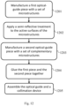
- a method for manufacturing an optical guide comprising the following steps is also proposed: manufacturing a first piece on the surface of which a set of microstructures is formed by applying the method mentioned above; applying a semi-reflective treatment to the surfaces of the microstructures intended to extract an image injected and propagated by successive total internal reflections in the optical guide; manufacturing a second piece on the surface of which a set of microstructures complementary to the microstructures of the first piece is formed; gluing the first piece and the second piece together, the microstructures on the surface of the first piece being glued facing their complementary microstructures on the surface of the second piece.
- the method comprises the following steps for manufacturing the second piece:
- a method for manufacturing an optical device comprising the following steps is also proposed: manufacturing an optical guide by applying the method as mentioned above; and assembling the optical guide and a collimation device, so that the collimation device injects an image, in the form of a beam collimated to infinity, through an injection zone of the optical guide, so that this image is transported by successive total internal reflections as far as an extraction zone of the optical guide where the glued microstructures are arranged to extract the image from the optical guide in see-through superimposition.
- FIG. 1 schematically illustrates microstructures of an optical-guide extraction zone, according to the prior art
- FIG. 2 A schematically illustrates another arrangement of an optical-guide extraction zone, according to the prior art
- FIG. 2 B schematically illustrates an arrangement of an optical-guide extraction zone, according to the prior art
- FIG. 3 schematically illustrates a diamond turning station
- FIG. 4 schematically illustrates the placement, with respect to a rotation axis of a drum of the diamond-turning station, of the surface of a piece to be machined to form microstructures of optical-guide extraction zones, according to an embodiment of the invention
- FIG. 5 schematically illustrates the following of a cutting profile by a diamond tip
- FIG. 6 schematically illustrates microstructures of an optical-guide extraction zone, obtained by operating the diamond-turning station in accordance with FIG. 4 ;
- FIG. 7 schematically illustrates the placement, with respect to the rotation axis of the drum of the diamond-turning station, of a piece to be machined to form an optical-guide extraction zone, according to another embodiment of the invention
- FIG. 8 schematically illustrates microstructures of an optical-guide extraction zone, obtained by operating the diamond turning station in accordance with FIG. 7 ;
- FIG. 9 schematically illustrates the placement, with respect to the rotation axis of the drum of the diamond turning station, of another piece to be machined, making it possible to form on its surface microstructures geometrically complementary to those obtained by operating the diamond turning station in accordance with FIG. 7 ;
- FIG. 10 schematically illustrates putting microstructures obtained by operating the diamond turning station in accordance with FIG. 7 and geometrically complementary microstructures obtained by operating the diamond turning station in accordance with FIG. 9 facing each other;
- FIG. 11 schematically illustrates steps of a method for manufacturing microstructures of an optical-guide extraction zone, or of an insert for moulding such microstructures of an optical-guide extraction zone;
- FIG. 12 schematically illustrates steps of a method for manufacturing an optical guide comprising two pieces, one piece comprising extraction-zone microstructures obtained by applying the method of FIG. 11 and the other piece comprising geometrically complementary microstructures.
- FIG. 3 thus schematically illustrates a diamond turning station 300 .
- the diamond station comprises a first chassis part 301 comprising a drum 304 on which a piece P to be cut can be attached.
- the drum 304 can be rotated with respect to the first chassis part 301 about an axis C (for example horizontal) so as to rotate R the piece P about the axis C.
- the diamond turning station comprises a second chassis part 302 comprising a cutting tool 303 with diamond tip.
- the cutting tool 303 with diamond tip can be moved and locked with respect to rotation about an axis perpendicular to the axis C (for example vertical), so as to be able to adjust the presentation angle of the cutting tool 303 with regard to the rotating piece P.
- the first chassis part 301 and the second chassis part 302 can be moved in translation with respect to each other on a direct orthonormal reference frame X, Y, Z.
- the first chassis part 301 can make translations T X along the axis X and translations T Y along the axis Y
- the second chassis part 302 can make translations T Z along the axis Z.
- the movements of the cutting tool 303 relative to the piece P are controlled by a list of timestamped coordinates generated by a computer.
- the piece to be created is first of all described by means of a CAD (computer-aided design) model and then converted into instructions that can be interpreted by a controller or a processor of the numerical control machine that manages in particular the movement commands of the cutting tool 303 and/or of the first chassis part 301 and/or of the second chassis part 302 .
- the extraction zone consisting of a set of juxtaposed prismatic microstructures, is to be formed on the surface of the optical guide.
- the cutting profile can be applied directly to the optical guide to be created or to its insert (complementary form).
- each active surface A (or of its insert profile) is perpendicular to the rotation axis C, which makes it possible to obtain a planar surface.
- the piece P to be cut is offset with respect to the rotation axis C, which makes it possible to obtain, without recalibration of the diamond turning station 300 , active surfaces A that are planar and parallel to each other.
- a counterweight can be placed on the drum 304 in a suitable manner so as to limit the vibrations when the piece P is rotated about the rotation axis C.
- each microstructure thus formed is produced by the rotation of the piece P about the rotation axis C and the translation of the cutting tool along the axis X. Therefore only two movements of freedom are needed for creating each active surface A.
- Each passive surface B for its part requires three movements of freedom: the rotation about the rotation axis C of the piece P and the translations of the diamond tip along the axes X and Z. Increasing the movements of freedom necessary for producing a surface increases the imprecision (addition of tolerances of all the movements of freedom necessary). In this approach, the defect in surface shape is therefore smaller on the active surfaces A than on the passive surface B, but the surface roughness is of the same quality.
- FIG. 5 schematically illustrates the following of a cutting profile by a diamond tip 500 .
- the cutting actually obtained is slightly offset with respect to the cutting profile 400 followed by the diamond tip 500 .
- the diamond tip 500 has in fact a slightly rounded shape and the path followed by the diamond tip 500 is described with respect to the centre of this rounded part. Account is therefore taken of this offset related to the rounded shape of the diamond tip 500 when the diamond turning station 300 is programmed.
- FIG. 6 schematically illustrates microstructures 601 obtained by applying the configuration of the diamond turning station 300 shown in FIG. 4 , and by activating the rotation of the piece P about the axis C, and then manoeuvring the cutting tool 303 with diamond tip according to the cutting profile 400 .
- the active surfaces A 602 thus obtained are slices of discs and the passive surfaces B 603 thus obtained are frustoconical or cylindrical surfaces.
- the shapes thus obtained by diamond turning are not perfectly planar, but frustoconical (or cylindrical) on the passive surfaces B.
- These passive surfaces B are not intended to be provided with a reflective (or semi-reflective) treatment and do not serve to extract the image transported in the optical guide.
- the microstructures in the extraction zone are used by placing geometrically complementary microstructures facing them in order to afford a see-through effect.
- the surfaces facing said passive surfaces B are also preferentially devoid of any reflective (or semi-reflective) treatment. Then, although these passive surfaces B are not planar, the superimposition thereof on microstructures with complementary shapes ensures total and perfect transparency of the rays passing through the optical guide for see-through vision.
- the active surfaces A may be spherical.
- the progression of the relative movement of the diamond tip with the piece P along the axis Z is then synchronised with the rotation about the axis C.
- the diamond tip must in fact move in the course of the rotation about the axis C, during the cutting, in order to create a spherical profile; and along the axis X, the diamond tip also follows a spherical profile.
- numerical control machines are limited by three factors with regard to their movement on the axis Z: their maximum movement, their operating frequency and their acceleration.
- the “Fast Tool Servo FTS 5000” machine from Precitech which is dedicated to this type of application, has a maximum movement of 5000 ⁇ m, an operating frequency of 440 Hz for 100 ⁇ m of movement, and a maximum acceleration of 400 m/s 2 .
- these have a much lower maximum acceleration.
- the cutting profile of the active surfaces A forms an arc of a circle with a radius Rx (the radius along the axis X).
- Rx the radius along the axis X.
- the profile of the active surfaces A is concave.
- the profile of the active surfaces A is convex.
- the movements of the cutting tool 304 relative to the piece P also take place here, step by step (for example by movement steps of 0.5 ⁇ m on the axis X and/or on the axis Y and/or on the axis Z), according to a cutting profile 700 , as illustrated schematically on FIG. 7 .
- a cutting profile 700 as illustrated schematically on FIG. 7 .
- FIG. 8 schematically illustrates microstructures 801 obtained by applying the configuration of the diamond turning station 300 shown on FIG. 7 , and by activating the rotation of the piece P about the axis C, and then manoeuvring the cutting tool 303 with diamond tip according to the cutting profile 700 .
- the value of the angle Theta is to be adjusted according to a radius of curvature Ry (the radius along the axis Y) required in the long direction of the microstructures and according to the distance D between the axis C and the geometric centre of the set of microstructures (extraction zone of the optical guide) to be machined.
- a radius of curvature Ry the radius along the axis Y
- the centre of the circle of radius Ry is located on the rotation axis C of the drum 304 .
- the angle Theta is consequently fixed for all the microstructures. Keeping the angle Theta fixed makes it possible not to have to recalibrate the diamond turning station 300 by passing from the machining of one microstructure to the machining of the following one.
- the active surfaces A thus obtained are therefore toric surfaces very close to spherical surfaces, and have slight astigmatism, which is negligible in this case. This astigmatism is smaller, the closer the fixed reference frame used for defining the distance D (and consequently the angle Theta) is to the geometric centre of the set of microstructures to be machined.
- the distance D is such that all the microstructures to be machined are on the same side of the rotation axis C; in addition, the distance D is defined according to the physical capabilities of the diamond turning station 300 and the dimensions of the piece P to be machined, so as to minimise the variations in thickness between the middle and the ends of the microstructures (in the direction of their length).
- the placement of the piece P with respect to the rotation axis C of the drum 304 , and the machining by turning mean that the thickness of the microstructure differs between the middle of each microstructure and its ends.
- the inscription on the surfaces A and B of radii of curvature of a determined value is possible for the two directions, parallel or perpendicular to the cutting direction, and this for each prism.
- These radii Rx and Ry may be different for one and the same microstructure (prism), since they are independent (achievable by movements along distinct axes in the diamond turning station). This is because the radius Rx is inscribed by means of the cutting profile and the radius Ry is determined by the value of the tilt of the cutting axis, namely Theta.
- the active surfaces A of the microstructures thus obtained may have different values of radii Rx and Ry, it is possible to locally correct the vision of the user of the optical guide (and in particular a localised astigmatism). This is because the image extracted is provided with an optical power (after reflection of the microstructure) that will be able to be treated at each point of the extraction zone to focus an image at a fixed distance for a perfect eye, or to focus the image at the same fixed distance while taking account of an ophthalmic correction specific to the user by incorporating for each microstructure values Rx and Ry taking account of said ophthalmic correction (correction of the vision of the user).
- a first piece of optical guide comprises an extraction zone formed by microstructures obtained as previously described in relation to FIGS. 4 to 8 .
- a second optical-guide piece comprises geometrically complementary microstructures and overlaps the first piece. The refractive indices of the materials of the first piece and of the second piece, as well as the glue that assembles them, are substantially equal in order to ensure optical continuity.
- FIG. 9 schematically illustrates the placement, with respect to the rotation axis C, of another piece to be machined P′, making it possible to form on its surface microstructures geometrically complementary to those obtained by operating the diamond turning station in accordance with FIG. 7 .
- this other piece to be machined P′ is placed in the following manner on the diamond turning station 300 :
- radius Ry applied to the machining of the piece P′ is identical to the one applied to the machining of the piece P, in order to obtain microstructures that are geometrically complementary.
- the piece P′ is machined following a cutting profile 700 ′, as illustrated on FIG. 9 .
- the piece P′ is shown on the other side of the axis C with respect to the piece P shown on FIG. 7 (the machining means that the piece turns about the axis C).
- the positioning of the piece P′ and the cutting profile 700 ′ mean that the surfaces of microstructures of the piece P′ that are intended to be placed facing said passive surfaces B of the microstructures of the piece P have their back to the axis C.
- the cutting profile 700 ′ is geometrically complementary to the cutting profile 700 used for machining the microstructures on the surface of the piece P.
- FIG. 9 there appears the concave form of the surfaces that are intended to be placed facing the active surfaces A of the microstructures of the piece P, which for their part have a convex shape on FIG. 7 .
- the top part of the piece P′ on FIG. 9 is abraded during the diamond turning.
- FIG. 10 schematically illustrates putting the microstructures of the two pieces P and P′ of FIG. 9 facing each other after machining.
- An optical guide 1000 allowing the see-through effect (glue omitted on FIG. 10 ) and, superimposed, the extraction of the transported image is thus produced.
- the tilt of the pieces P and P′ at the angles Theta and Omega gives rise to a variation in thickness, characteristic of the method used for manufacturing the microstructures (or the inserts thereof).
- FIG. 11 schematically illustrates steps of the method for manufacturing microstructures of an optical-guide extraction zone, or of an insert for moulding such microstructures of an optical-guide extraction zone.
- the piece P is positioned on the drum 304 of the diamond turning station 300 :
- a step 1102 the piece P is held in position on the drum.
- a counterweight may be added to compensate for the offset in mass due to the placement of the piece out of alignment with respect to the axis C of the drum and thus avoid vibrations caused.
- the piece to be machined P is placed and held in position as illustrated schematically on FIG. 4 or on FIG. 7 .
- a step 1103 the drum is set in rotation about the axis C.
- a step 1104 cutting by diamond tip is implemented, and the diamond tip is moved along the required cutting profile.
- the microstructures of an optical-guide extraction zone, or of an insert for moulding such microstructures of an optical-guide extraction zone, are thus produced.
- a step 1105 the rotation of the drum is stopped.
- a step 1106 the piece P is disconnected from the drum.
- the piece P thus produced can therefore serve for producing an optical guide and more particularly for producing extraction-zone microstructures, or their complementary microstructures (as in accordance with the principle of FIG. 10 ), or of their insert used in moulding and plastic injection operations.
- the manufacture of these microstructures, as disclosed here is sufficiently quicker than with straight-line diamond machining (shaping machine). Shapes (cylindrical, frustoconical) slightly different from those ideally required (respectively planar, spherical) for a given optical application are obtained. This difference in general shape of each microstructure does not cause any deformation of the see-through vision.
- this embodiment ensures that its light rays are certainly slightly diverted, in accordance with the curvature of the active surfaces A, but remain parallel to each other for each image pixel when they are transported by guidance in the optical guide.
- FIG. 12 schematically illustrates steps of a method for manufacturing an optical guide comprising two pieces, a first piece comprising extraction-zone microstructures obtained by applying the method of FIG. 11 and a second piece comprising geometrically complementary microstructures.
- a first optical guide piece is manufactured, for example by machining a piece P made from plastics material or glass or by plastic injection method.
- the first piece comprises microstructures on the surface that serve for extracting an image injected into the optical guide.
- the microstructures, or a moulding insert of these microstructures, are obtained as detailed previously, more particularly in relation to FIG. 11 .
- a semi-reflective treatment (deposition) is applied to the active surfaces of the microstructures obtained during the step 1201 .
- a step 1004 the first piece manufactured at the step 1001 and the second piece manufactured at the step 1003 are glued together, the microstructures on the surface of the first piece being glued facing their complementary microstructures on the surface of the second piece, as illustrated on FIG. 10 .
- the refractive indices of the materials used for manufacturing the first piece and the second piece, and of the glue that assembles them, are substantially equal in order to ensure optical continuity.
Landscapes
- Engineering & Computer Science (AREA)
- Physics & Mathematics (AREA)
- Manufacturing & Machinery (AREA)
- Chemical & Material Sciences (AREA)
- Mechanical Engineering (AREA)
- Optics & Photonics (AREA)
- General Physics & Mathematics (AREA)
- Ophthalmology & Optometry (AREA)
- Health & Medical Sciences (AREA)
- General Chemical & Material Sciences (AREA)
- Materials Engineering (AREA)
- Organic Chemistry (AREA)
- Geochemistry & Mineralogy (AREA)
- Chemical Kinetics & Catalysis (AREA)
- Life Sciences & Earth Sciences (AREA)
- Ceramic Engineering (AREA)
- Optical Elements Other Than Lenses (AREA)
- Turning (AREA)
Abstract
Description
-
- installing a piece P to be machined on the drum as follows: the piece P to be machined is offset by a distance D from the rotation axis of the drum, the distance D being the distance that separates the axis C and a reference frame fixed in relation to the microstructures to be machined; and the piece P to be machined is placed so that there is a mean angle Theta between the axis C and a cutting profile corresponding to the active surfaces, the angle Theta being as follows:
Theta=arccos (D/Ry) - where Ry is a required radius of curvature in the long direction of the microstructures;
- moving the diamond tip along the cutting profile of the microstructures by actuating the rotation of the drum so as to machine all the microstructures on the surface of the piece P to be machined.
- installing a piece P to be machined on the drum as follows: the piece P to be machined is offset by a distance D from the rotation axis of the drum, the distance D being the distance that separates the axis C and a reference frame fixed in relation to the microstructures to be machined; and the piece P to be machined is placed so that there is a mean angle Theta between the axis C and a cutting profile corresponding to the active surfaces, the angle Theta being as follows:
-
- installing another piece P′ to be machined on the drum as follows: the other piece P′ to be machined is offset by a distance D′ from the rotation axis of the drum, the distance D being identical to the distance D used for manufacturing the first piece; and the other piece P′ to be machined is placed so that there is a mean angle Omega between the axis C and another cutting profile corresponding to the surfaces intended to be placed facing the active surfaces of the microstructures of the first piece, the angle Omega being as follows:
Omega=π-Theta=π-arccos (D/Ry) - moving the diamond tip along said other cutting profile of the microstructures by actuating the rotation of the drum so as to machine all the microstructures on the surface of the other piece P′ to be machined, said other cutting profile being geometrically complementary to the cutting profile used for machining the first piece.
- installing another piece P′ to be machined on the drum as follows: the other piece P′ to be machined is offset by a distance D′ from the rotation axis of the drum, the distance D being identical to the distance D used for manufacturing the first piece; and the other piece P′ to be machined is placed so that there is a mean angle Omega between the axis C and another cutting profile corresponding to the surfaces intended to be placed facing the active surfaces of the microstructures of the first piece, the angle Omega being as follows:
-
- the piece P is placed at a distance D from the rotation axis C of the
drum 304, the distance D being the distance that separates the axis C and a reference frame fixed in relation to the set of microstructures to be machined. Preferentially, this fixed reference frame is the geometric centre of the set of microstructures to be machined, i.e. the geometric centre of the extraction zone. This fixed reference frame may be another reference point with a position predefined in relation to the set of microstructures to be machined. For example, a point on an edge of the set of microstructures, or a point around the set of microstructures on the piece P. It should be noted that the distance D is limited by the physical capacities of thediamond turning station 300, in particular the dimension of thedrum 304, as well as by the dimensions of the piece P. - the piece P to be machined is placed so that there is an angle Theta=90° between the axis C and the cutting profile of the active surfaces A to be formed.
- the piece P is placed at a distance D from the rotation axis C of the
Theta=arccos (D/Ry)
It can moreover be noted that, when Ry tends towards infinity (cutting profile perpendicular to the axis C), Theta=90° is found as in
-
- this other piece to be machined P′ is placed at a distance D′ from the rotation axis C of the
drum 304, the distance D′ being the distance that separates the axis C and a fixed reference frame in relation to all the microstructures to be machined. This fixed reference frame is the same reference frame, in relation to the piece P′, as the one used for the distance D in relation to the piece P, so that the microstructures of the piece P′ are machined to allow their placement opposite those of the piece P. The distance D′ is identical to the distance D. Preferentially, this fixed reference frame is the geometric centre of the set of microstructures to be machined. It should be noted that the distance D′ is limited by the physical capacities of thediamond turning station 300, in particular the dimension of thedrum 304, as well as by the dimensions of the piece P′. - the piece to be machined P′ is placed so that there is an angle Omega=π-Theta between the axis C and the cutting profile of the surfaces of microstructures that are intended to be placed facing the active surfaces A of the microstructures of the piece P.
- this other piece to be machined P′ is placed at a distance D′ from the rotation axis C of the
Omega=π-Theta=π-arccos (D/Ry)=π-arccos (D′/Ry)
-
- the piece to be machined P is offset by a distance D from the rotation axis of the
drum 304, the distance D being the distance that separates the axis C and the geometric centre of the set of microstructures to be machined; - the piece to be machined P is placed so that there is a mean angle Theta=arccos (D/Ry) between the axis C and the cutting profile of the active surfaces A to be formed.
- the piece to be machined P is offset by a distance D from the rotation axis of the
Claims (12)
Theta=arccos (D/Ry)
Omega=π-Theta=π-arccos (D/Ry)
Omega=π-arccos (D/Ry)
Theta=arccos (D/Ry)
Applications Claiming Priority (3)
| Application Number | Priority Date | Filing Date | Title |
|---|---|---|---|
| EP21305215 | 2021-02-23 | ||
| EP21305215.2 | 2021-02-23 | ||
| EP21305215.2A EP4046784B1 (en) | 2021-02-23 | 2021-02-23 | Method for manufacturing a set of optical guide microstructures |
Publications (2)
| Publication Number | Publication Date |
|---|---|
| US20220357503A1 US20220357503A1 (en) | 2022-11-10 |
| US12345912B2 true US12345912B2 (en) | 2025-07-01 |
Family
ID=74856802
Family Applications (1)
| Application Number | Title | Priority Date | Filing Date |
|---|---|---|---|
| US17/677,417 Active 2043-08-15 US12345912B2 (en) | 2021-02-23 | 2022-02-22 | Method for manufacturing a set of optical guide microstructures |
Country Status (2)
| Country | Link |
|---|---|
| US (1) | US12345912B2 (en) |
| EP (1) | EP4046784B1 (en) |
Citations (9)
| Publication number | Priority date | Publication date | Assignee | Title |
|---|---|---|---|---|
| EP0440578A1 (en) | 1990-01-24 | 1991-08-07 | Ciba-Geigy Ag | Device for machining curved planes onto moulds for optical or ophthalmic lenses |
| WO2009074638A2 (en) | 2007-12-13 | 2009-06-18 | Optinvent | Optical guide and ocular vision optical system |
| WO2012136470A1 (en) | 2011-04-05 | 2012-10-11 | Optinvent | Optical guidance device and method of manufacturing such a device |
| US8662959B2 (en) * | 2008-11-12 | 2014-03-04 | Toshiba Kikai Kabushiki Kaisha | Cutting method and cutting device for hard material |
| US20140140091A1 (en) | 2012-11-20 | 2014-05-22 | Sergiy Victorovich Vasylyev | Waveguide illumination system |
| US9207662B2 (en) | 2008-09-18 | 2015-12-08 | Flir Systems Trading Belgium Bvba | Systems and methods for machining materials |
| US20170322417A1 (en) * | 2014-12-04 | 2017-11-09 | Dai Nippon Printing Co., Ltd. | Semi-transmissive reflection sheet, light guide plate and display device |
| US10203437B2 (en) | 2014-09-12 | 2019-02-12 | Canon Kabushiki Kaisha | Method of manufacturing a member, optical member and optical element |
| CN110244399A (en) | 2019-05-30 | 2019-09-17 | 开平市盈光机电科技有限公司 | A manufacturing process of optical microstructure on the wedge-shaped surface of the core of the moving mold of the light guide plate |
-
2021
- 2021-02-23 EP EP21305215.2A patent/EP4046784B1/en active Active
-
2022
- 2022-02-22 US US17/677,417 patent/US12345912B2/en active Active
Patent Citations (9)
| Publication number | Priority date | Publication date | Assignee | Title |
|---|---|---|---|---|
| EP0440578A1 (en) | 1990-01-24 | 1991-08-07 | Ciba-Geigy Ag | Device for machining curved planes onto moulds for optical or ophthalmic lenses |
| WO2009074638A2 (en) | 2007-12-13 | 2009-06-18 | Optinvent | Optical guide and ocular vision optical system |
| US9207662B2 (en) | 2008-09-18 | 2015-12-08 | Flir Systems Trading Belgium Bvba | Systems and methods for machining materials |
| US8662959B2 (en) * | 2008-11-12 | 2014-03-04 | Toshiba Kikai Kabushiki Kaisha | Cutting method and cutting device for hard material |
| WO2012136470A1 (en) | 2011-04-05 | 2012-10-11 | Optinvent | Optical guidance device and method of manufacturing such a device |
| US20140140091A1 (en) | 2012-11-20 | 2014-05-22 | Sergiy Victorovich Vasylyev | Waveguide illumination system |
| US10203437B2 (en) | 2014-09-12 | 2019-02-12 | Canon Kabushiki Kaisha | Method of manufacturing a member, optical member and optical element |
| US20170322417A1 (en) * | 2014-12-04 | 2017-11-09 | Dai Nippon Printing Co., Ltd. | Semi-transmissive reflection sheet, light guide plate and display device |
| CN110244399A (en) | 2019-05-30 | 2019-09-17 | 开平市盈光机电科技有限公司 | A manufacturing process of optical microstructure on the wedge-shaped surface of the core of the moving mold of the light guide plate |
Non-Patent Citations (2)
| Title |
|---|
| Jiang et al.; "Novel tool offset fly cutting straight-groove-type micro structure arrays;" Journal of Materials Processing Tech.; 2021; pp. 1-14; vol. 288, No. 116900. |
| Jul. 28, 2021 Search Report issued in European Patent Application No. 21 30 5215. |
Also Published As
| Publication number | Publication date |
|---|---|
| US20220357503A1 (en) | 2022-11-10 |
| EP4046784B1 (en) | 2024-08-21 |
| EP4046784A1 (en) | 2022-08-24 |
Similar Documents
| Publication | Publication Date | Title |
|---|---|---|
| CN1823294B (en) | Alignment method and device for display device components | |
| CN109070502B (en) | Method for manufacturing curved eyepieces | |
| TWI463217B (en) | Optical sheet laminating method, optical sheet laminating device and program used therewith, and display device | |
| US8999210B2 (en) | Method of manufacturing a lens for providing an optical display | |
| KR101388181B1 (en) | Laser cutting apparatus for glass substrate and method for cutting glass substrate | |
| SG194130A1 (en) | Adhesive dispensing profile enhancement | |
| US12345912B2 (en) | Method for manufacturing a set of optical guide microstructures | |
| GB2608724A (en) | Encapsulation of thin films within eyeglass lenses | |
| CN101138807A (en) | Cutting equipment and cutting manufacturing process | |
| JP4146196B2 (en) | Composite optical device and manufacturing method thereof | |
| US20150338657A1 (en) | Display device | |
| CN105659144A (en) | Method for encapsulating a light-guide optical element in a transparent capsule | |
| WO2020256944A1 (en) | Lens with internal aperture | |
| EP4316769A1 (en) | Mold manufacturing method, optical member manufacturing method, and spectacle lens | |
| CN116964512B (en) | Thin film encapsulation in eyeglass lenses | |
| CN120779609B (en) | Display panel, display device and method for manufacturing aspheric columnar lens | |
| CN100434964C (en) | Method for manufacturing f theta lens of laser scanning device | |
| US20250162337A1 (en) | Locally modified waveguide total thickness variation | |
| WO2024171998A1 (en) | Method for manufacturing spectacle lens, semi-finished lens, spectacle lens, and spectacles | |
| JP2021039258A (en) | Method of manufacturing optical element, and optical element | |
| US20200030918A1 (en) | Processing method, processing system, processing program, and data structure | |
| WO2022119665A1 (en) | System and method for radius of curvature modification of optical plates and lenses by irradiation with optical energy | |
| GB2611887A (en) | Encapsulation of thin films within eyeglass lenses | |
| JP2015045794A (en) | Optical element, optical element manufacturing method, and image display apparatus | |
| JPH1110502A (en) | Manufacturing device and manufacturing method for refractive index distribution type lens |
Legal Events
| Date | Code | Title | Description |
|---|---|---|---|
| FEPP | Fee payment procedure |
Free format text: ENTITY STATUS SET TO UNDISCOUNTED (ORIGINAL EVENT CODE: BIG.); ENTITY STATUS OF PATENT OWNER: SMALL ENTITY |
|
| AS | Assignment |
Owner name: OPTINVENT, FRANCE Free format text: ASSIGNMENT OF ASSIGNORS INTEREST;ASSIGNORS:SARRAYEDINE, KHALED;JULIEN, SIMON;LIU, YAO;REEL/FRAME:059282/0827 Effective date: 20220228 |
|
| FEPP | Fee payment procedure |
Free format text: ENTITY STATUS SET TO SMALL (ORIGINAL EVENT CODE: SMAL); ENTITY STATUS OF PATENT OWNER: SMALL ENTITY |
|
| STPP | Information on status: patent application and granting procedure in general |
Free format text: DOCKETED NEW CASE - READY FOR EXAMINATION |
|
| STPP | Information on status: patent application and granting procedure in general |
Free format text: NON FINAL ACTION MAILED |
|
| STCF | Information on status: patent grant |
Free format text: PATENTED CASE |