US12343811B2 - Systems and methods for ultrasonic repair - Google Patents
Systems and methods for ultrasonic repair Download PDFInfo
- Publication number
- US12343811B2 US12343811B2 US18/213,600 US202318213600A US12343811B2 US 12343811 B2 US12343811 B2 US 12343811B2 US 202318213600 A US202318213600 A US 202318213600A US 12343811 B2 US12343811 B2 US 12343811B2
- Authority
- US
- United States
- Prior art keywords
- tool
- repair
- welding
- machining
- repaired
- Prior art date
- Legal status (The legal status is an assumption and is not a legal conclusion. Google has not performed a legal analysis and makes no representation as to the accuracy of the status listed.)
- Active, expires
Links
Images


Classifications
-
- B—PERFORMING OPERATIONS; TRANSPORTING
- B23—MACHINE TOOLS; METAL-WORKING NOT OTHERWISE PROVIDED FOR
- B23P—METAL-WORKING NOT OTHERWISE PROVIDED FOR; COMBINED OPERATIONS; UNIVERSAL MACHINE TOOLS
- B23P6/00—Restoring or reconditioning objects
-
- B—PERFORMING OPERATIONS; TRANSPORTING
- B23—MACHINE TOOLS; METAL-WORKING NOT OTHERWISE PROVIDED FOR
- B23K—SOLDERING OR UNSOLDERING; WELDING; CLADDING OR PLATING BY SOLDERING OR WELDING; CUTTING BY APPLYING HEAT LOCALLY, e.g. FLAME CUTTING; WORKING BY LASER BEAM
- B23K20/00—Non-electric welding by applying impact or other pressure, with or without the application of heat, e.g. cladding or plating
- B23K20/10—Non-electric welding by applying impact or other pressure, with or without the application of heat, e.g. cladding or plating making use of vibrations, e.g. ultrasonic welding
-
- B—PERFORMING OPERATIONS; TRANSPORTING
- B23—MACHINE TOOLS; METAL-WORKING NOT OTHERWISE PROVIDED FOR
- B23K—SOLDERING OR UNSOLDERING; WELDING; CLADDING OR PLATING BY SOLDERING OR WELDING; CUTTING BY APPLYING HEAT LOCALLY, e.g. FLAME CUTTING; WORKING BY LASER BEAM
- B23K20/00—Non-electric welding by applying impact or other pressure, with or without the application of heat, e.g. cladding or plating
- B23K20/26—Auxiliary equipment
-
- B—PERFORMING OPERATIONS; TRANSPORTING
- B23—MACHINE TOOLS; METAL-WORKING NOT OTHERWISE PROVIDED FOR
- B23P—METAL-WORKING NOT OTHERWISE PROVIDED FOR; COMBINED OPERATIONS; UNIVERSAL MACHINE TOOLS
- B23P15/00—Making specific metal objects by operations not covered by a single other subclass or a group in this subclass
-
- B—PERFORMING OPERATIONS; TRANSPORTING
- B23—MACHINE TOOLS; METAL-WORKING NOT OTHERWISE PROVIDED FOR
- B23P—METAL-WORKING NOT OTHERWISE PROVIDED FOR; COMBINED OPERATIONS; UNIVERSAL MACHINE TOOLS
- B23P23/00—Machines or arrangements of machines for performing specified combinations of different metal-working operations not covered by a single other subclass
- B23P23/04—Machines or arrangements of machines for performing specified combinations of different metal-working operations not covered by a single other subclass for both machining and other metal-working operations
-
- B—PERFORMING OPERATIONS; TRANSPORTING
- B23—MACHINE TOOLS; METAL-WORKING NOT OTHERWISE PROVIDED FOR
- B23P—METAL-WORKING NOT OTHERWISE PROVIDED FOR; COMBINED OPERATIONS; UNIVERSAL MACHINE TOOLS
- B23P2700/00—Indexing scheme relating to the articles being treated, e.g. manufactured, repaired, assembled, connected or other operations covered in the subgroups
- B23P2700/01—Aircraft parts
-
- B—PERFORMING OPERATIONS; TRANSPORTING
- B23—MACHINE TOOLS; METAL-WORKING NOT OTHERWISE PROVIDED FOR
- B23P—METAL-WORKING NOT OTHERWISE PROVIDED FOR; COMBINED OPERATIONS; UNIVERSAL MACHINE TOOLS
- B23P6/00—Restoring or reconditioning objects
- B23P6/002—Repairing turbine components, e.g. moving or stationary blades, rotors
- B23P6/005—Repairing turbine components, e.g. moving or stationary blades, rotors using only replacement pieces of a particular form
-
- B—PERFORMING OPERATIONS; TRANSPORTING
- B64—AIRCRAFT; AVIATION; COSMONAUTICS
- B64F—GROUND OR AIRCRAFT-CARRIER-DECK INSTALLATIONS SPECIALLY ADAPTED FOR USE IN CONNECTION WITH AIRCRAFT; DESIGNING, MANUFACTURING, ASSEMBLING, CLEANING, MAINTAINING OR REPAIRING AIRCRAFT, NOT OTHERWISE PROVIDED FOR; HANDLING, TRANSPORTING, TESTING OR INSPECTING AIRCRAFT COMPONENTS, NOT OTHERWISE PROVIDED FOR
- B64F5/00—Designing, manufacturing, assembling, cleaning, maintaining or repairing aircraft, not otherwise provided for; Handling, transporting, testing or inspecting aircraft components, not otherwise provided for
- B64F5/40—Maintaining or repairing aircraft
Definitions
- the present disclosure relates to systems and methods for repair and more particularly to systems and methods for ultrasonic repair.
- the method can further include installing a repair tool adapter into the repair tool, the repair tool adapter configured for both axial movement and rotational movement when installed in the repair tool holder.
- Installing the welding tool into the repair tool holder can include installing a welding tool tip into the repair tool adapter and installing the machining tool into the repair tool holder can include installing a machining tool tip into the repair tool adapter and installing the repair tool adapter to the repair tool holder.
- aligning the weld tool tip can include, using an alignment system (e.g., an interferometer or a touch probe), measuring the relative position of the weld tool tip to the part to be repaired and comparing the measured relative position to the predetermined offset for the welding tool.
- aligning the machining tool tip can include, using the alignment system, measuring the relative position of the machining tool tip to the part to be repaired and comparing the measured relative position to the predetermined offset for the machining tool.
- the method can be performed automatically, e.g., at least, installing the respective tools, removing/changing the respective tools, ultrasonic welding and ultrasonic machining.
- repair system can include a repair tool, a repair tool adapter operatively interfaced with the repair tool, and a plurality of differing tool heads configured to be inserted into the repair tool adapter such that the repair tool is configured for both ultrasonic welding and ultrasonic machining.
- the system can include one or more ultrasonic transducers disposed in the repair tool configured to convert ultrasonic vibration to heat energy and/or cutting energy such that the tool is configured for both ultrasonic welding and ultrasonic machining.
- the repair tool can also include a holding portion configured to be inserted into or grasped by a motive system to move the repair tool over a part to be repaired.
- the repair system can include the motive system and in certain embodiments, the motive system includes a gantry.
- the gantry can be part of a CNC machine.
- the system can include an optical interferometer in optical communication with the repair tool configured to inspect and measure a position of the repair tool head relative to a part to be repaired.
- the system can include a controller and the controller can be configured to compare the measured relative position of the repair too head to a predetermined offset for the repair tool head.
- the controller can be configured to control the motive system to reposition the repair tool head relative to the part to be repaired based at least in part on the measurement data comparison.
- the predetermined offset for the repair tool head can be based on a type of repair tool head or another parameter of the repair tool head.
- FIG. 1 is an exploded view of an embodiment of a repair tool in accordance with this disclosure
- FIG. 2 is an enlarged partial view of an ultrasonic portion of the repair tool of FIG. 1 ;
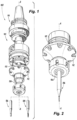
- FIG. 3 is an assembled view of the repair tool of FIG. 1 ;
- FIG. 3 A is an enlarged view of an embodiment of a tool head inserted into the repair tool
- FIG. 3 B is an enlarged view of an embodiment of another tool head inserted into the repair tool
- FIG. 4 is a schematic perspective view of a system in accordance with this disclosure, showing the repair tool of FIG. 1 in an embodiment of a motive system;
- FIG. 5 is a schematic view of an embodiment of an alignment system of the system of FIG. 4 ;
- FIGS. 6 A- 6 B show a schematic diagram of an embodiment of a method of repairing a part using repair tool of FIG. 1 ;
- FIGS. 7 A- 7 B show a schematic diagram of another embodiment of a method of repairing a part using repair tool of FIG. 1 ;
- FIGS. 8 A- 8 B show a schematic diagram of another embodiment of a method of repairing a part using repair tool of FIG. 1 .
- FIG. 1 an illustrative view of an embodiment of a system in accordance with the disclosure is shown in FIG. 1 and is designated generally by reference character 100 .
- FIGS. 2 - 8 Other embodiments and/or aspects of this disclosure are shown in FIGS. 2 - 8 .
- Certain embodiments can be used to repair parts in very small or complex/hard to reach locations where a conventional repair tool would be unable to reach, for example as discussed herein below with respect to FIGS. 6 - 8 B .
- Embodiments also allow for repairs without complete disassembly of the part to be repaired.
- repair system 100 can include a repair tool 102 , a repair tool adapter 104 operatively interfaced with the repair tool 102 , and a plurality of differing tool heads 106 , 108 configured to be inserted into the repair tool adapter 104 such that the repair tool is configured for both ultrasonic welding and ultrasonic machining.
- the repair tool adapter 104 can include a collet configured to act similar to a chuck to accept the one or more differing repair tool heads 106 , 108 within the same adapter 104 , and without requiring a change of the repair tool 102 as a whole.
- the collet 104 is also configured to allow longitudinal, axial motion of a welding tool head 106 during ultrasonic welding, and rotation of a machining tool head 108 during ultrasonic machining.
- One or more ultrasonic transducers 110 can be disposed in the repair tool 102 configured to convert ultrasonic vibration to heat energy (e.g., for ultrasonic welding) and/or cutting energy (e.g., for ultrasonic machining) such that the repair tool is configured for both ultrasonic welding and ultrasonic machining.
- a horn 112 can be included configured to focus the ultrasonic vibration from the transducers to the tool head 106 , 108 .
- the repair tool 102 can also include a holding portion 114 configured to be inserted into or grasped by a motive system 116 to move the repair tool 102 over bed 118 having a part to be repaired 120 .
- the system 100 can include the motive system 116 , and the motive system 116 can include a grabbing portion 122 configured to grab the holding portion 114 of the repair tool 102 .
- the motive system 116 includes a gantry 124 .
- the repair system 100 can include a CNC machine, and the gantry 124 can be part of the CNC machine.
- the holding portion 114 of the repair tool 102 can be formed or designed to fit a general CNC machine, or can be formed or designed to fit a particular CNC machine model. In certain embodiments, the holding portion 114 of the repair tool 102 can be formed or designed to fit another type of repair system, such as an HSK solid tool holding system, a CAT tapered tool holder, or a BT tool holder, for example.
- the system 100 can also include a controller 126 , e.g., for controlling the motive system 116 .
- the controller 126 can be or include a CNC controller configured to control the motive system 116 to move the repair tool 102 on the gantry 118 over the part to be repaired 120 and to perform the necessary repair functions, e.g., the welding and machining.
- the controller 126 can be configured to move the motive system 116 in 5 axes.
- the controller 126 can be programmed by a number of user inputs, such as the type and size of the part to be repaired 120 , the material of the part to be repaired 120 , a desired pressure and speed or frequency of the tool 106 , 108 based on the material, and/or tool size, among others.
- the system 100 can include an alignment system 128 .
- the alignment system can be an optical interferometer in optical communication with the repair tool 102 configured to inspect and measure a position of the repair tool head 106 , 108 relative to a part to be repaired 120 .
- the alignment system can include a touch probe system, which can be similarly employed as the interferometer to inspect and measure the position of the repair tool head.
- a controller 130 (e.g., together with or separate from controller 126 ) can be configured to compare the measured relative position of the repair too head 106 , 108 to a predetermined offset (e.g., axial and radial) for the repair tool head.
- the axial and radial offset refers to a distance between the tool 102 and the part to be repaired 120 in both the axial and radial directions, along the tool to the spindle interface.
- the offset can also include an angular offset, the angle of the tool head 106 , 108 oriented relative to the part to be repaired 120 .
- the optical interferometer system 128 can include an optical transmitter 132 (e.g., a laser transmitter) configured to transmit an optical beam 134 , and an optical receiver 136 positioned opposite from the transmitter 132 configured to receive the optical beam 134 .
- One or more optical elements 138 e.g., lenses and/or mirrors
- the controller 126 , 130 can be configured to control the motive system 116 to reposition the repair tool 102 and/or the repair tool head 106 , 108 relative to the part to be repaired 120 based at least in part on the measurement data comparison, for example, if the measured offset does not match the predetermined offset after changing the tool head 106 , 108 .
- the predetermined offset for the repair tool head 106 , 108 can be based on a type of repair tool head or another parameter of the repair tool head.
- the parameters can include, among others, the type of repair tool head (e.g., welding or machining), the size of the repair tool head and/or a manufacturer of the repair tool head.
- Each of these parameters may affect the offset from the part to be repaired as different manufacturers may have different shapes or orientations of the same tool heads, for example. Aligning the tool head each time based on these parameters allows the system 100 to accept a wide variety of tool heads including many tool types and tool heads from different suppliers. In some cases, the offset between the welding and machining tool head may be the same.
- a method (e.g., a method of repairing a part) can include installing a repair tool adapter (e.g., adapter 104 ) into a repair tool (e.g., tool 102 ), the repair tool adapter configured to allow both axial movement and rotational movement of a repair tool head (e.g., tool head 106 , 108 ) when installed in the repair tool holder.
- a repair tool adapter e.g., adapter 104
- a repair tool e.g., tool 102
- the repair tool adapter configured to allow both axial movement and rotational movement of a repair tool head (e.g., tool head 106 , 108 ) when installed in the repair tool holder.
- the method can further include installing a welding tool (e.g., tool head 106 ) into the repair tool adapter, ultrasonic welding a repair sheet 142 to a part to be repaired with the welding tool (e.g., as shown in FIGS. 6 A, 7 A, 8 A ), removing the welding tool from the repair tool adapter, installing a machining tool (e.g., tool head 108 ) into the repair tool adapter, and ultrasonic machining the portion of the repair sheet that is welded to the part to be repaired to match a predetermined geometry of the part to be repaired with the machining tool (e.g., as shown in 6 B, 7 B, 8 B).
- a welding tool e.g., tool head 106
- ultrasonic welding a repair sheet 142 to a part to be repaired with the welding tool
- a machining tool e.g., tool head 108
- the repair sheet 142 can include sheet metal, for example, or any other suitable material that matches or is compatible with a base material of a part to be repaired.
- the repair sheet can be sheet metal.
- FIGS. 6 A- 8 B show embodiments of a method for repairing an outside engine casing or flange ( FIG. 6 A, 6 B ), an inner side engine casing or flange ( FIG. 7 A, 7 B ), and detailed tooling ( FIG. 8 A, 8 B ).
- the method can include, after installing the welding tool into the repair tool adapter, aligning the welding tool tip relative to the part to be repaired based on a predetermined offset for the welding tool tip.
- the method can include, after installing the machining tool into the repair tool adapter, aligning the machining tool tip relative to the part to be repaired based on a predetermined offset for the machining tool tip.
- the predetermined offset for the welding tool tip and predetermined offset for the machining tool tip can be the same or in embodiments, the predetermined offset for the welding tool tip and predetermined offset for the machining tool tip can be different based on one or more repair tool parameters (e.g., as discussed above with respect to system 100 ).
- aligning the weld tool tip can include, using an interferometer (e.g., interferometer system 128 ), measuring the relative position of the weld tool tip to the part to be repaired and comparing the measured relative position to the predetermined offset for the welding tool.
- aligning the machining tool tip can include, using the interferometer, measuring the relative position of the machining tool tip to the part to be repaired and comparing the measured relative position to the predetermined offset for the machining tool.
- the method can be performed automatically.
- the repair tool holder is installed into the motive system (e.g., motive system 116 ) and the controller (e.g., controller 126 , 130 ) is programmed as needed for the given application, installing the respective tool heads, removing/changing the respective tool heads, ultrasonic welding, and ultrasonic machining can all be performed automatically by the system, and without further user input.
- the motive system e.g., motive system 116
- the controller e.g., controller 126 , 130
- MRO maintenance, repair and overhaul
- the current typical repair workflow for a worn/damaged metal component can include scanning and analysis, repair process by deposition, real time monitoring and machining, which are typically performed at different machines to obtain a good form accuracy and surface finish.
- these processes are well established individually, few solutions to repair parts with limited working envelope or very small clearance for tools, such as engine casing/flange or in between turbine blades, are available.
- the absence of a fully integrated and automatic repair solution represents a significant challenge for reducing adoption barriers such as repair versatility, capital investment, time to deploy, safety, and data flow management.
- Embodiments of the systems and methods described herein therefore offer a solution to these concerns by providing for an automatic repair process, bringing together the ultrasonic welding and ultrasonic machining during the repair process.
- Ultrasonic welding is a joining process including using high frequency ultrasonic vibrations (e.g., about 20-40 kHz) to convert electrical energy into heat.
- This process can be used to join plastics as well as most of metals, where high frequency vibrations together with pressure applied can join two materials quickly and securely, without the need of large amounts of heat as in traditional welding process.
- Using ultrasonic vibration as described herein can provide a number of advantages over conventional processes, including lower energy consumption and reduced process cost.
- the ultrasonic energy for welding can be used for thermal softening, and experimental results reveal that the ultrasonic energy required to produce an identical amount of softening is much less than the required thermal energy.
- Ultrasonic welding can also eliminate subjective elements in the welding process, ensuring consistent quality and can allow for quick and easy setup, e.g., when moving from one set up to another, for example.
- FIGS. 1 and 2 show an embodiment of an ultrasonic tooling system with at least three components: transducer(s) 110 , a horn 112 , and tool head 106 , 108 .
- the electrical energy input to the transducer is converted to mechanical vibrations along its longitudinal axis A at high frequency (e.g., about at 20-40 kHz).
- the excited vibration is subsequently transmitted through an energy-focusing horn to amplify the vibration amplitude and finally delivered to the tool tip.
- the tool which is placed directly above the workpiece during a repair, can vibrate along its longitudinal axis with a desired amplitude.
- the respective tools and tool heads can be additively manufactured to create unique tool geometries selected tool materials.
- the tool length can be measured with the on-machine tool measurement system (e.g., the interferometer system described above) as shown in FIG. 5 to get the tool diameter and length offset for each tool assembly.
- Welded strength is largely affected by the magnitude of the welding energy and required duration. Welding energy required for welding decreases as welding pressure increases, typically welding pressure for metals varies from about 5 to about 60 MPa (or 80-960 N for a pressurizing area of 16 mm 2 ). With the increase of welding pressure, required energy and duration can be shortened.
- vibration frequency can be determined by the tooling design, for example tool length. Once the tooling design is selected, the vibration frequency is fixed, thus the main parameter to optimize is the vibration amplitude. With the increase of vibration amplitude, welding energy increases, which also shortens welding duration or fast feed rates for welding.
- Benefits of multistep ultrasonic system and methods for repair as disclosed herein include improving the process efficiency, shortening cycle time and avoiding part transfer when switching between the different processes. Embodiments allow for accurate positioning of the tooling for both processes. Additionally, the loads for both ultrasonic welding and machining are significantly smaller than traditional friction stir welding and high-speed milling, respectively, which helps to reduce part deformation during repair process to keep the geometries within tolerance.
- any numerical values disclosed herein can be exact values or can be values within a range. Further, any terms of approximation (e.g., “about”, “approximately”, “around”) used in this disclosure can mean the stated value within a range. For example, in certain embodiments, the range can be within (plus or minus) 20%, or within 10%, or within 5%, or within 2%, or within any other suitable percentage or number as appreciated by those having ordinary skill in the art (e.g., for known tolerance limits or error ranges).
- a reference to “A and/or B”, when used in conjunction with open-ended language such as “comprising” can refer, in one embodiment, to A only (optionally including elements other than B); in another embodiment, to B only (optionally including elements other than A); in yet another embodiment, to both A and B (optionally including other elements); etc.
Landscapes
- Engineering & Computer Science (AREA)
- Mechanical Engineering (AREA)
- Pressure Welding/Diffusion-Bonding (AREA)
- Automatic Tool Replacement In Machine Tools (AREA)
Abstract
Description
Claims (13)
Priority Applications (2)
| Application Number | Priority Date | Filing Date | Title |
|---|---|---|---|
| US18/213,600 US12343811B2 (en) | 2023-06-23 | 2023-06-23 | Systems and methods for ultrasonic repair |
| EP24182858.1A EP4487989A1 (en) | 2023-06-23 | 2024-06-18 | Systems and methods for ultrasonic repair |
Applications Claiming Priority (1)
| Application Number | Priority Date | Filing Date | Title |
|---|---|---|---|
| US18/213,600 US12343811B2 (en) | 2023-06-23 | 2023-06-23 | Systems and methods for ultrasonic repair |
Publications (2)
| Publication Number | Publication Date |
|---|---|
| US20240424597A1 US20240424597A1 (en) | 2024-12-26 |
| US12343811B2 true US12343811B2 (en) | 2025-07-01 |
Family
ID=91585679
Family Applications (1)
| Application Number | Title | Priority Date | Filing Date |
|---|---|---|---|
| US18/213,600 Active 2043-07-06 US12343811B2 (en) | 2023-06-23 | 2023-06-23 | Systems and methods for ultrasonic repair |
Country Status (2)
| Country | Link |
|---|---|
| US (1) | US12343811B2 (en) |
| EP (1) | EP4487989A1 (en) |
Citations (39)
| Publication number | Priority date | Publication date | Assignee | Title |
|---|---|---|---|---|
| US4870743A (en) * | 1987-10-13 | 1989-10-03 | Extrude Hone Corporation | Quick change tool assembly for ultrasonic machine tool |
| EP0367395A2 (en) * | 1988-10-27 | 1990-05-09 | Aitkens, Terry K. | Rapid change tool and cutter driving systems |
| US5079070A (en) * | 1990-10-11 | 1992-01-07 | International Business Machines Corporation | Repair of open defects in thin film conductors |
| RU1245U1 (en) * | 1992-12-30 | 1995-12-16 | Виктор Михайлович Гусев | Universal chuck for automated tool mounting in the machine spindle |
| JPH1044242A (en) | 1996-08-06 | 1998-02-17 | Denso Corp | Ultrasonic processing apparatus |
| JPH11314168A (en) * | 1998-04-28 | 1999-11-16 | Arutekusu:Kk | Ultrasonic vibration bonding resonator |
| US6089438A (en) * | 1995-08-14 | 2000-07-18 | Yazaki Corporation | Ultrasonic welder |
| US6280125B1 (en) * | 1998-08-15 | 2001-08-28 | Marc H Boisvert | R-8 collet |
| DE20208872U1 (en) * | 2002-06-07 | 2002-10-24 | Sonotronic Nagel GmbH, 76307 Karlsbad | Ultrasonic welding machine |
| DE10225588B4 (en) * | 2002-06-07 | 2005-03-31 | Sonotronic Nagel Gmbh | Ultrasonic welding machine |
| US6932876B1 (en) * | 1998-09-03 | 2005-08-23 | U.I.T., L.L.C. | Ultrasonic impact machining of body surfaces to correct defects and strengthen work surfaces |
| US20050210796A1 (en) * | 2004-03-26 | 2005-09-29 | Doka Industrie Gmbh | Formwork component |
| JP3983609B2 (en) | 2002-06-24 | 2007-09-26 | 松下電器産業株式会社 | Component mounting tool and component mounting method and apparatus using the same |
| JP2008279692A (en) * | 2007-05-11 | 2008-11-20 | Toyo Unso Kk | Repair method of pallet |
| US20100243612A1 (en) | 2007-12-04 | 2010-09-30 | Rolls-Royce Plc | Electrical discharge machining |
| DE102011006932A1 (en) | 2011-04-07 | 2012-10-11 | Widmann Maschinen E.K. | Apparatus, useful for welding, cutting and/or punching workpieces by ultrasound, comprises ultrasonic sonotrode, and counter tool as well as drive for displacing sonotrode or counter tool independent of ultrasonic welding movement |
| US20130292913A1 (en) * | 2012-04-13 | 2013-11-07 | Guehring Ohg | Hydro-expansion chuck |
| US20140272248A1 (en) * | 2013-03-15 | 2014-09-18 | Rolls-Royce Corporation | Ceramic matrix composite repair by reactive processing and mechanical interlocking |
| US20150068663A1 (en) * | 2013-09-06 | 2015-03-12 | GM Global Technology Operations LLC | Apparatus and methods for repairing discrepant welds |
| US9446475B2 (en) | 2014-04-09 | 2016-09-20 | Fabrisonic, Llc | Weld assembly for ultrasonic additive manufacturing applications |
| GB2548801A (en) * | 2016-03-21 | 2017-10-04 | Loop Tech Ltd | A system for machining a surface |
| US9878377B2 (en) | 2010-03-11 | 2018-01-30 | Edison Industrial Innovation, Llc | High-speed rotary electrical connector for use in ultrasonically assisted machining |
| DE102014118296B4 (en) * | 2013-12-13 | 2018-04-12 | GM Global Technology Operations LLC (n. d. Ges. d. Staates Delaware) | A method of monitoring a status condition of a vibration welder and vibration welding system |
| CN108772621A (en) * | 2018-08-01 | 2018-11-09 | 苏州凯尔博精密机械有限公司 | A kind of ultrasonic bonding rifle of Z axis rotation tool changing |
| US20200020661A1 (en) * | 2018-07-16 | 2020-01-16 | Asm Technology Singapore Pte Ltd | Bonding apparatus with replaceable bonding tool |
| US20200086424A1 (en) | 2017-03-22 | 2020-03-19 | Hybrid Manufacturing Technologies Limited | A machine tool |
| US20200122358A1 (en) * | 2018-10-19 | 2020-04-23 | Arris Composites Inc. | Method and System for Creating Three-Dimensional Preforms for Use in Composite Parts |
| US20200238414A1 (en) | 2019-01-30 | 2020-07-30 | Shanghai Jiao Tong University | Multifunctional Integrated Manufacturing System Based On Electrical Arc And Discharge Machining |
| CN111468816A (en) * | 2020-05-25 | 2020-07-31 | 常青智能科技(天津)有限公司 | An automatic ultrasonic flexible welding system |
| DE102019107539A1 (en) * | 2019-03-25 | 2020-10-01 | Weber Ultrasonics AG | Frame for a processing machine and method for processing a workpiece with the same |
| EP3756808A1 (en) * | 2018-02-24 | 2020-12-30 | Dalian University Of Technology | Ultrasonic cutting holder for honeycomb core |
| CN112222596A (en) * | 2020-10-20 | 2021-01-15 | 天津市捷威动力工业有限公司 | Ultrasonic welding method for soft package lithium battery tab |
| CN112809159A (en) * | 2021-01-21 | 2021-05-18 | 长春富维安道拓汽车饰件系统有限公司 | Integrated double-ultrasonic welding unit |
| CN113245686A (en) * | 2020-02-11 | 2021-08-13 | 广州市科普超声电子技术有限公司 | Multifunctional ultrasonic tool head |
| CN114311690A (en) * | 2020-09-30 | 2022-04-12 | 福特全球技术公司 | Agile robot headlamp assembly |
| CN115091022A (en) * | 2022-07-06 | 2022-09-23 | 重庆理工大学 | Friction stir welding-based crack repairing and micro-additive method |
| CN115781181A (en) * | 2022-09-19 | 2023-03-14 | 江苏星业精密滚子科技有限公司 | Method for milling and grinding all-in-one roller ball base surface through five-axis five-linkage |
| WO2024107232A1 (en) * | 2022-11-18 | 2024-05-23 | Gary Lee Ward | Concentrated longitudinal acoustical/ultrasonic energy fastener design and manipulation system having at least one or a plurality of flexible ultrasonic joints |
| US20240217192A1 (en) * | 2023-01-03 | 2024-07-04 | Rohr, Inc. | Method of repairing thermoplastic composite components with manual ultrasonic weld |
-
2023
- 2023-06-23 US US18/213,600 patent/US12343811B2/en active Active
-
2024
- 2024-06-18 EP EP24182858.1A patent/EP4487989A1/en active Pending
Patent Citations (39)
| Publication number | Priority date | Publication date | Assignee | Title |
|---|---|---|---|---|
| US4870743A (en) * | 1987-10-13 | 1989-10-03 | Extrude Hone Corporation | Quick change tool assembly for ultrasonic machine tool |
| EP0367395A2 (en) * | 1988-10-27 | 1990-05-09 | Aitkens, Terry K. | Rapid change tool and cutter driving systems |
| US5079070A (en) * | 1990-10-11 | 1992-01-07 | International Business Machines Corporation | Repair of open defects in thin film conductors |
| RU1245U1 (en) * | 1992-12-30 | 1995-12-16 | Виктор Михайлович Гусев | Universal chuck for automated tool mounting in the machine spindle |
| US6089438A (en) * | 1995-08-14 | 2000-07-18 | Yazaki Corporation | Ultrasonic welder |
| JPH1044242A (en) | 1996-08-06 | 1998-02-17 | Denso Corp | Ultrasonic processing apparatus |
| JPH11314168A (en) * | 1998-04-28 | 1999-11-16 | Arutekusu:Kk | Ultrasonic vibration bonding resonator |
| US6280125B1 (en) * | 1998-08-15 | 2001-08-28 | Marc H Boisvert | R-8 collet |
| US6932876B1 (en) * | 1998-09-03 | 2005-08-23 | U.I.T., L.L.C. | Ultrasonic impact machining of body surfaces to correct defects and strengthen work surfaces |
| DE20208872U1 (en) * | 2002-06-07 | 2002-10-24 | Sonotronic Nagel GmbH, 76307 Karlsbad | Ultrasonic welding machine |
| DE10225588B4 (en) * | 2002-06-07 | 2005-03-31 | Sonotronic Nagel Gmbh | Ultrasonic welding machine |
| JP3983609B2 (en) | 2002-06-24 | 2007-09-26 | 松下電器産業株式会社 | Component mounting tool and component mounting method and apparatus using the same |
| US20050210796A1 (en) * | 2004-03-26 | 2005-09-29 | Doka Industrie Gmbh | Formwork component |
| JP2008279692A (en) * | 2007-05-11 | 2008-11-20 | Toyo Unso Kk | Repair method of pallet |
| US20100243612A1 (en) | 2007-12-04 | 2010-09-30 | Rolls-Royce Plc | Electrical discharge machining |
| US9878377B2 (en) | 2010-03-11 | 2018-01-30 | Edison Industrial Innovation, Llc | High-speed rotary electrical connector for use in ultrasonically assisted machining |
| DE102011006932A1 (en) | 2011-04-07 | 2012-10-11 | Widmann Maschinen E.K. | Apparatus, useful for welding, cutting and/or punching workpieces by ultrasound, comprises ultrasonic sonotrode, and counter tool as well as drive for displacing sonotrode or counter tool independent of ultrasonic welding movement |
| US20130292913A1 (en) * | 2012-04-13 | 2013-11-07 | Guehring Ohg | Hydro-expansion chuck |
| US20140272248A1 (en) * | 2013-03-15 | 2014-09-18 | Rolls-Royce Corporation | Ceramic matrix composite repair by reactive processing and mechanical interlocking |
| US20150068663A1 (en) * | 2013-09-06 | 2015-03-12 | GM Global Technology Operations LLC | Apparatus and methods for repairing discrepant welds |
| DE102014118296B4 (en) * | 2013-12-13 | 2018-04-12 | GM Global Technology Operations LLC (n. d. Ges. d. Staates Delaware) | A method of monitoring a status condition of a vibration welder and vibration welding system |
| US9446475B2 (en) | 2014-04-09 | 2016-09-20 | Fabrisonic, Llc | Weld assembly for ultrasonic additive manufacturing applications |
| GB2548801A (en) * | 2016-03-21 | 2017-10-04 | Loop Tech Ltd | A system for machining a surface |
| US20200086424A1 (en) | 2017-03-22 | 2020-03-19 | Hybrid Manufacturing Technologies Limited | A machine tool |
| EP3756808A1 (en) * | 2018-02-24 | 2020-12-30 | Dalian University Of Technology | Ultrasonic cutting holder for honeycomb core |
| US20200020661A1 (en) * | 2018-07-16 | 2020-01-16 | Asm Technology Singapore Pte Ltd | Bonding apparatus with replaceable bonding tool |
| CN108772621A (en) * | 2018-08-01 | 2018-11-09 | 苏州凯尔博精密机械有限公司 | A kind of ultrasonic bonding rifle of Z axis rotation tool changing |
| US20200122358A1 (en) * | 2018-10-19 | 2020-04-23 | Arris Composites Inc. | Method and System for Creating Three-Dimensional Preforms for Use in Composite Parts |
| US20200238414A1 (en) | 2019-01-30 | 2020-07-30 | Shanghai Jiao Tong University | Multifunctional Integrated Manufacturing System Based On Electrical Arc And Discharge Machining |
| DE102019107539A1 (en) * | 2019-03-25 | 2020-10-01 | Weber Ultrasonics AG | Frame for a processing machine and method for processing a workpiece with the same |
| CN113245686A (en) * | 2020-02-11 | 2021-08-13 | 广州市科普超声电子技术有限公司 | Multifunctional ultrasonic tool head |
| CN111468816A (en) * | 2020-05-25 | 2020-07-31 | 常青智能科技(天津)有限公司 | An automatic ultrasonic flexible welding system |
| CN114311690A (en) * | 2020-09-30 | 2022-04-12 | 福特全球技术公司 | Agile robot headlamp assembly |
| CN112222596A (en) * | 2020-10-20 | 2021-01-15 | 天津市捷威动力工业有限公司 | Ultrasonic welding method for soft package lithium battery tab |
| CN112809159A (en) * | 2021-01-21 | 2021-05-18 | 长春富维安道拓汽车饰件系统有限公司 | Integrated double-ultrasonic welding unit |
| CN115091022A (en) * | 2022-07-06 | 2022-09-23 | 重庆理工大学 | Friction stir welding-based crack repairing and micro-additive method |
| CN115781181A (en) * | 2022-09-19 | 2023-03-14 | 江苏星业精密滚子科技有限公司 | Method for milling and grinding all-in-one roller ball base surface through five-axis five-linkage |
| WO2024107232A1 (en) * | 2022-11-18 | 2024-05-23 | Gary Lee Ward | Concentrated longitudinal acoustical/ultrasonic energy fastener design and manipulation system having at least one or a plurality of flexible ultrasonic joints |
| US20240217192A1 (en) * | 2023-01-03 | 2024-07-04 | Rohr, Inc. | Method of repairing thermoplastic composite components with manual ultrasonic weld |
Non-Patent Citations (2)
| Title |
|---|
| Extended European Search Report for EP Application No. 24182858.1, dated Dec. 9, 2024, 9 pages. |
| V.K. Nadimpalli, et al., "Monitoring and repair of defects in ultrasonic additive manufacturing", from The Int'l. Journal of Advanced Manufacturing Technology, 2020, pp. 1793-1810. |
Also Published As
| Publication number | Publication date |
|---|---|
| EP4487989A1 (en) | 2025-01-08 |
| US20240424597A1 (en) | 2024-12-26 |
Similar Documents
| Publication | Publication Date | Title |
|---|---|---|
| JP3763734B2 (en) | Panel member processing method | |
| CN108746616B (en) | Manufacturing method and device for composite additive and subtractive material by coaxial powder feeding and laser forging | |
| US20200238414A1 (en) | Multifunctional Integrated Manufacturing System Based On Electrical Arc And Discharge Machining | |
| CN104093523B (en) | Composite processing method and composite processing device | |
| EP1614497A1 (en) | Method and apparatus for repairing or building up surfaces on a workpiece while the workpiece is mounted on a machine tool | |
| CN109366492A (en) | Robot-based online compensation system and method for casting grinding track | |
| US20130134141A1 (en) | Laser assisted machining system for ceramics and hard materials | |
| KR20210031465A (en) | machine tool | |
| CN104308438B (en) | A kind of fluid torque-converter lid wheel assembly contiguous block weld jig and technique thereof | |
| CN108994549A (en) | A kind of manufacturing process of vacuum chamber | |
| JPH04289038A (en) | Composte machine tool capable of laser process | |
| JP4647179B2 (en) | Processing method | |
| JP2004243393A (en) | Laser welding system | |
| US20090304515A1 (en) | Method and device for joining by way of inductive hf pressure welding a rotor blade with a rotor support of a gas turbine with automatic supply of the rotor blade | |
| US12343811B2 (en) | Systems and methods for ultrasonic repair | |
| US20060243709A1 (en) | Method and device for restoring and producing geometrically complex components | |
| JP2004249305A (en) | Laser welding method and laser welding system | |
| CN119910295B (en) | Laser ultrasonic cooperative texture cutter dynamic gap heat dissipation composite processing device and method | |
| EP3117946B1 (en) | Linear friction welding method | |
| CN118342140A (en) | A method for drilling micro holes in SiCf/SiC composite materials | |
| Boehm | Hybrid manufacturing of turbine components: laser metal deposition (LMD) and adaptive repair for higher precision and shorter production time | |
| US20110167632A1 (en) | Device and method for machining and assembling a piston | |
| Liang et al. | Precise micro-assembly through an integration of micro-EDM and Nd-YAG | |
| CN115647485A (en) | High-precision spiral bevel gear milling machine and machining method | |
| CN208262850U (en) | Robotic laser welds grinding device |
Legal Events
| Date | Code | Title | Description |
|---|---|---|---|
| FEPP | Fee payment procedure |
Free format text: ENTITY STATUS SET TO UNDISCOUNTED (ORIGINAL EVENT CODE: BIG.); ENTITY STATUS OF PATENT OWNER: LARGE ENTITY |
|
| AS | Assignment |
Owner name: PRATT & WHITNEY, CONNECTICUT Free format text: ASSIGNMENT OF ASSIGNORS INTEREST;ASSIGNOR:FURRER, DAVID ULRICH;REEL/FRAME:065105/0453 Effective date: 20230621 Owner name: RAYTHEON TECHNOLOGIES CORPORATION, VIRGINIA Free format text: ASSIGNMENT OF ASSIGNORS INTEREST;ASSIGNORS:WANG, ZHIGANG;EL-WARDANY, TAHANY I.;KUCZEK, ANDRZEJ ERNEST;SIGNING DATES FROM 20230602 TO 20230626;REEL/FRAME:065105/0300 |
|
| AS | Assignment |
Owner name: RTX CORPORATION, CONNECTICUT Free format text: CHANGE OF NAME;ASSIGNOR:RAYTHEON TECHNOLOGIES CORPORATION;REEL/FRAME:067697/0983 Effective date: 20230711 |
|
| AS | Assignment |
Owner name: RTX CORPORATION, CONNECTICUT Free format text: ASSIGNMENT OF ASSIGNORS INTEREST;ASSIGNOR:FURRER, DAVID;REEL/FRAME:068095/0464 Effective date: 20240618 |
|
| AS | Assignment |
Owner name: HAMILTON SUNDSTRAND CORPORATION, NORTH CAROLINA Free format text: ASSIGNMENT OF ASSIGNORS INTEREST;ASSIGNOR:RTX CORPORATION;REEL/FRAME:068865/0354 Effective date: 20241004 |
|
| STPP | Information on status: patent application and granting procedure in general |
Free format text: NON FINAL ACTION MAILED |
|
| STPP | Information on status: patent application and granting procedure in general |
Free format text: RESPONSE TO NON-FINAL OFFICE ACTION ENTERED AND FORWARDED TO EXAMINER |
|
| STPP | Information on status: patent application and granting procedure in general |
Free format text: NOTICE OF ALLOWANCE MAILED -- APPLICATION RECEIVED IN OFFICE OF PUBLICATIONS |
|
| STCF | Information on status: patent grant |
Free format text: PATENTED CASE |