US1233792A - Sled attachment for perambulators. - Google Patents
Sled attachment for perambulators. Download PDFInfo
- Publication number
- US1233792A US1233792A US14208917A US14208917A US1233792A US 1233792 A US1233792 A US 1233792A US 14208917 A US14208917 A US 14208917A US 14208917 A US14208917 A US 14208917A US 1233792 A US1233792 A US 1233792A
- Authority
- US
- United States
- Prior art keywords
- sled
- carriage
- perambulators
- runners
- axles
- Prior art date
- Legal status (The legal status is an assumption and is not a legal conclusion. Google has not performed a legal analysis and makes no representation as to the accuracy of the status listed.)
- Expired - Lifetime
Links
Images
Classifications
-
- B—PERFORMING OPERATIONS; TRANSPORTING
- B62—LAND VEHICLES FOR TRAVELLING OTHERWISE THAN ON RAILS
- B62B—HAND-PROPELLED VEHICLES, e.g. HAND CARTS OR PERAMBULATORS; SLEDGES
- B62B13/00—Sledges with runners
- B62B13/18—Vehicles having alternatively-usable runners and wheels or other transport means
Definitions
- the object of my invention is to provide an inexpensive, light and durable sled attachment adapted to be removably mounted upon the axles of a wheeled perambulator and designed to be quickly and easily thrown into and out of service position, so that the peran'ibulator may be instantly converted into a sled or carriage, as desired.
- a further object is to provide a device of this kind having means to yieldingly hold the sled in elevated inoperative position, said means being also adapted to yieldingly secure the sled latching mechanism when said sled is in position for service.
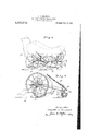
- Figure 1 is a perspective view, illustrating in solid lines my improved device and in dotted lines a wheeled perambulator to which said device is attached; and Fig. 2 is an enlarged detail longitudinal central sectional view, taken through the rear axle of the perambulator.
- my sled attachment comprises a pair of runners 10 joined by means of a tie brace 11 and U-shaped links 12, the latter being connected with said runners and attached to the axles 13 of a carriage 14.
- a latching member 15 on the sled engages the rear axle of the carriage and secures said sled in operative position.
- This latching member is connected with a tension spring 16 which is secured to the body of the carriage 14 and serves two functions, viz: to yieldingly hold the sled in elevated position when out of service and to yieldingly secure the latching member 15 in engagement with the rear axle of the carriage when the sled is ⁇ depressed for use.
- the runners 10 are identical, each runner being formed with kerfs 17, near its ends, having upright rear abutments 18 and intermediate kerfs 19.
- the tie brace 11 is U-shaped and the ends thereoil are seated in the kerfs 19 and rigidlysecured to the runners by means of rivets or bolts 20.
- the links 12 are also U-shaped, the legs 12a thereof being inserted in the kerfs 17 in the runners 10 and pivotally secured therein by Specification of Letters Patent.
- the connections between the links 12 and axles 13 consist of L- shaped bolts or clips which pass through perforations in the axles of the carriage and are secured to said axles by means of nuts' 28. Each pair of clips serves as alined journals 24 upon which one of the links 12 is mounted.
- These links swing from pendant position to rearwardly inclined position (Fig. 2). In the former position the runners l0 are depressed and support the carriage, the wheels thereof being held above the ground; while in the latter position of said links the runners are elevated, the carriage then being supported upon said wheels.
- the latch member 15 comprises a rod which is bent nearthe rear end thereof to form a catch 25 and near its forward end looped to form an eye 26.
- the spring 16 is secured at its lower end in-a second eye 28 on the forward end of the rod 15 and passes upwardly and rearwardly to a point beneath the body of the carriage where it is secured to said body by means of a screw eye (not shown) or other suitable means.
- This spring supports the sled when not in service 1n elevated position (dotted lines, Fig. 2) and also holds the rear end of the rod l5 against the rear axle 13 of the carriage, thereby preventing the rod from rattling and also yieldingly securing the catch 25 on said rod in engagement with said axle (Fig. 2) when the sled is depressed for service.
- the simplicity of my device, the ease with which it may be manipulated and its convenience of application to a carriage constitute important features of the present invention.
Description
yF. D. KENDRICK. SL50 ATTACHMENT FR PERAMBULATOHS. APPLICATION FILED JAN. 12. 1917.
,@fgf@ Patented July 1?, 1917.
FAYQETTE D. KENDRICK, OF ST. PAUL, MINNESOTA.
SLED ATTACHMENT FOR PERAMBULATORS.
Application filed January 12, 1917.
To all 'whom t may concern.'
Be itknown that I, FAYETTE D. KENDRIGK, a citizen of the United States, residing at St. Paul, in the county of Ramsey and State of Minnesota, have invented new and useful Improvements in Sled Attachments for Perambulators, of which the following is a specication.
The object of my invention is to provide an inexpensive, light and durable sled attachment adapted to be removably mounted upon the axles of a wheeled perambulator and designed to be quickly and easily thrown into and out of service position, so that the peran'ibulator may be instantly converted into a sled or carriage, as desired.
A further object is to provide a device of this kind having means to yieldingly hold the sled in elevated inoperative position, said means being also adapted to yieldingly secure the sled latching mechanism when said sled is in position for service.
lin the drawings, Figure 1 is a perspective view, illustrating in solid lines my improved device and in dotted lines a wheeled perambulator to which said device is attached; and Fig. 2 is an enlarged detail longitudinal central sectional view, taken through the rear axle of the perambulator.
Referring to the drawings, it will be seen that my sled attachment comprises a pair of runners 10 joined by means of a tie brace 11 and U-shaped links 12, the latter being connected with said runners and attached to the axles 13 of a carriage 14. A latching member 15 on the sled engages the rear axle of the carriage and secures said sled in operative position. This latching member is connected with a tension spring 16 which is secured to the body of the carriage 14 and serves two functions, viz: to yieldingly hold the sled in elevated position when out of service and to yieldingly secure the latching member 15 in engagement with the rear axle of the carriage when the sled is `depressed for use.
The runners 10 are identical, each runner being formed with kerfs 17, near its ends, having upright rear abutments 18 and intermediate kerfs 19. The tie brace 11 is U-shaped and the ends thereoil are seated in the kerfs 19 and rigidlysecured to the runners by means of rivets or bolts 20. The links 12 are also U-shaped, the legs 12a thereof being inserted in the kerfs 17 in the runners 10 and pivotally secured therein by Specification of Letters Patent.
Patented July 1"?, 1917. serial No. 142,089.
means of rivets or bolts 21 passing through said legs and runners. The connections between the links 12 and axles 13 consist of L- shaped bolts or clips which pass through perforations in the axles of the carriage and are secured to said axles by means of nuts' 28. Each pair of clips serves as alined journals 24 upon which one of the links 12 is mounted. These links swing from pendant position to rearwardly inclined position (Fig. 2). In the former position the runners l0 are depressed and support the carriage, the wheels thereof being held above the ground; while in the latter position of said links the runners are elevated, the carriage then being supported upon said wheels. The latch member 15 comprises a rod which is bent nearthe rear end thereof to form a catch 25 and near its forward end looped to form an eye 26. An eye bolt 27, secured at the center of the tie bar 11, passes through said eye 26 and pivotally secures the rod 15 uponv the sled. The spring 16 is secured at its lower end in-a second eye 28 on the forward end of the rod 15 and passes upwardly and rearwardly to a point beneath the body of the carriage where it is secured to said body by means of a screw eye (not shown) or other suitable means. This spring supports the sled when not in service 1n elevated position (dotted lines, Fig. 2) and also holds the rear end of the rod l5 against the rear axle 13 of the carriage, thereby preventing the rod from rattling and also yieldingly securing the catch 25 on said rod in engagement with said axle (Fig. 2) when the sled is depressed for service. The simplicity of my device, the ease with which it may be manipulated and its convenience of application to a carriage constitute important features of the present invention.
Having described my invention, what I claim as new and desire to protect by Letters Patent, is:
1. In a device of the character described, the combination with a carriage, of a sled arranged beneath the axles of said carriage, links connecting said sled with said axles and adapted to hold the sled in service position and also in elevated position, so that said carriage may be carried upon the sled or upon the wheels, a latching member mounted on said sled and designed to engage an axle of said carriage and a tension spring, secured to said carriage and latching member, adapted to yieldingly hold the Copies of this patent may be obtained for sled in elevated position and also to yieldingly secure said latching member` in engagement With said axle, When the sled is in position for service.
2. In a device ofthe character described,
the combination with a carriage, of a sled,
connecting links pivotaliy suspending said sled beneath the axles of the carriage, a tension spring,
latter' in elevated position, a latching meminterposed between theV vcarriage and sled, to yieldingly hold the Aber having a medial pivotal connection with ve cents each, by addressing the Commissioner of '.Latents` Washington, D. C.
Priority Applications (1)
| Application Number | Priority Date | Filing Date | Title |
|---|---|---|---|
| US14208917A US1233792A (en) | 1917-01-12 | 1917-01-12 | Sled attachment for perambulators. |
Applications Claiming Priority (1)
| Application Number | Priority Date | Filing Date | Title |
|---|---|---|---|
| US14208917A US1233792A (en) | 1917-01-12 | 1917-01-12 | Sled attachment for perambulators. |
Publications (1)
| Publication Number | Publication Date |
|---|---|
| US1233792A true US1233792A (en) | 1917-07-17 |
Family
ID=3301620
Family Applications (1)
| Application Number | Title | Priority Date | Filing Date |
|---|---|---|---|
| US14208917A Expired - Lifetime US1233792A (en) | 1917-01-12 | 1917-01-12 | Sled attachment for perambulators. |
Country Status (1)
| Country | Link |
|---|---|
| US (1) | US1233792A (en) |
Cited By (1)
| Publication number | Priority date | Publication date | Assignee | Title |
|---|---|---|---|---|
| US10023220B1 (en) * | 2017-05-16 | 2018-07-17 | Avedis Samuelian | Cart ski system |
-
1917
- 1917-01-12 US US14208917A patent/US1233792A/en not_active Expired - Lifetime
Cited By (1)
| Publication number | Priority date | Publication date | Assignee | Title |
|---|---|---|---|---|
| US10023220B1 (en) * | 2017-05-16 | 2018-07-17 | Avedis Samuelian | Cart ski system |
Similar Documents
| Publication | Publication Date | Title |
|---|---|---|
| US1255070A (en) | Barrel-truck. | |
| US1233792A (en) | Sled attachment for perambulators. | |
| US1193052A (en) | Tongue-support | |
| US241148A (en) | Combined wheelbarrow and truck | |
| US663526A (en) | Boy's wagon. | |
| US1207856A (en) | Detachable sleigh-runner. | |
| US411319A (en) | Wheelbarrow | |
| US154120A (en) | Improvement in sleigh-runners for wheeled vehicles | |
| US1220247A (en) | Snow-traveling attachment for motor-cycles. | |
| US384100A (en) | thomas | |
| US1207931A (en) | Attachment for combining go-carts with sleds. | |
| US593340A (en) | Push-bar for trolley-cars | |
| US1192002A (en) | Attachment to baby-carriages. | |
| US1218467A (en) | Sleigh-runner attachment for wagons. | |
| US1205220A (en) | Wheel attachment for sleighs or sleds. | |
| US818529A (en) | Wheelbarrow. | |
| US1234200A (en) | Sled-runner. | |
| US622503A (en) | Perambulator | |
| US437707A (en) | Sleigh-runner | |
| US1048365A (en) | Brake. | |
| US407715A (en) | George beebe | |
| US460949A (en) | Road-cart | |
| US553822A (en) | Runner for baby-carriages | |
| US766940A (en) | Runner for wheeled vehicles. | |
| US1095898A (en) | Attachment for sulkies. |