US12332437B2 - System and method for reducing image data throughput to head mounted display - Google Patents
System and method for reducing image data throughput to head mounted display Download PDFInfo
- Publication number
- US12332437B2 US12332437B2 US16/990,779 US202016990779A US12332437B2 US 12332437 B2 US12332437 B2 US 12332437B2 US 202016990779 A US202016990779 A US 202016990779A US 12332437 B2 US12332437 B2 US 12332437B2
- Authority
- US
- United States
- Prior art keywords
- hmd
- frame
- electronic device
- differential
- pixels
- Prior art date
- Legal status (The legal status is an assumption and is not a legal conclusion. Google has not performed a legal analysis and makes no representation as to the accuracy of the status listed.)
- Active, expires
Links
Images


Classifications
-
- G—PHYSICS
- G02—OPTICS
- G02B—OPTICAL ELEMENTS, SYSTEMS OR APPARATUS
- G02B27/00—Optical systems or apparatus not provided for by any of the groups G02B1/00 - G02B26/00, G02B30/00
- G02B27/01—Head-up displays
- G02B27/017—Head mounted
-
- G—PHYSICS
- G06—COMPUTING OR CALCULATING; COUNTING
- G06F—ELECTRIC DIGITAL DATA PROCESSING
- G06F3/00—Input arrangements for transferring data to be processed into a form capable of being handled by the computer; Output arrangements for transferring data from processing unit to output unit, e.g. interface arrangements
- G06F3/01—Input arrangements or combined input and output arrangements for interaction between user and computer
- G06F3/011—Arrangements for interaction with the human body, e.g. for user immersion in virtual reality
-
- H—ELECTRICITY
- H04—ELECTRIC COMMUNICATION TECHNIQUE
- H04N—PICTORIAL COMMUNICATION, e.g. TELEVISION
- H04N13/00—Stereoscopic video systems; Multi-view video systems; Details thereof
- H04N13/10—Processing, recording or transmission of stereoscopic or multi-view image signals
- H04N13/106—Processing image signals
- H04N13/161—Encoding, multiplexing or demultiplexing different image signal components
-
- G—PHYSICS
- G02—OPTICS
- G02B—OPTICAL ELEMENTS, SYSTEMS OR APPARATUS
- G02B27/00—Optical systems or apparatus not provided for by any of the groups G02B1/00 - G02B26/00, G02B30/00
- G02B27/0093—Optical systems or apparatus not provided for by any of the groups G02B1/00 - G02B26/00, G02B30/00 with means for monitoring data relating to the user, e.g. head-tracking, eye-tracking
-
- G—PHYSICS
- G02—OPTICS
- G02B—OPTICAL ELEMENTS, SYSTEMS OR APPARATUS
- G02B27/00—Optical systems or apparatus not provided for by any of the groups G02B1/00 - G02B26/00, G02B30/00
- G02B27/01—Head-up displays
- G02B27/0101—Head-up displays characterised by optical features
-
- G—PHYSICS
- G02—OPTICS
- G02B—OPTICAL ELEMENTS, SYSTEMS OR APPARATUS
- G02B27/00—Optical systems or apparatus not provided for by any of the groups G02B1/00 - G02B26/00, G02B30/00
- G02B27/01—Head-up displays
- G02B27/017—Head mounted
- G02B27/0172—Head mounted characterised by optical features
-
- G—PHYSICS
- G06—COMPUTING OR CALCULATING; COUNTING
- G06F—ELECTRIC DIGITAL DATA PROCESSING
- G06F3/00—Input arrangements for transferring data to be processed into a form capable of being handled by the computer; Output arrangements for transferring data from processing unit to output unit, e.g. interface arrangements
- G06F3/01—Input arrangements or combined input and output arrangements for interaction between user and computer
- G06F3/011—Arrangements for interaction with the human body, e.g. for user immersion in virtual reality
- G06F3/012—Head tracking input arrangements
-
- G06T11/006—
-
- G—PHYSICS
- G06—COMPUTING OR CALCULATING; COUNTING
- G06T—IMAGE DATA PROCESSING OR GENERATION, IN GENERAL
- G06T11/00—Two-dimensional [2D] image generation
- G06T11/60—Creating or editing images; Combining images with text
-
- G—PHYSICS
- G06—COMPUTING OR CALCULATING; COUNTING
- G06T—IMAGE DATA PROCESSING OR GENERATION, IN GENERAL
- G06T12/00—Tomographic reconstruction from projections
- G06T12/20—Inverse problem, i.e. transformations from projection space into object space
-
- G—PHYSICS
- G06—COMPUTING OR CALCULATING; COUNTING
- G06T—IMAGE DATA PROCESSING OR GENERATION, IN GENERAL
- G06T19/00—Manipulating three-dimensional [3D] models or images for computer graphics
- G06T19/20—Editing of three-dimensional [3D] images, e.g. changing shapes or colours, aligning objects or positioning parts
-
- H—ELECTRICITY
- H04—ELECTRIC COMMUNICATION TECHNIQUE
- H04N—PICTORIAL COMMUNICATION, e.g. TELEVISION
- H04N13/00—Stereoscopic video systems; Multi-view video systems; Details thereof
- H04N13/10—Processing, recording or transmission of stereoscopic or multi-view image signals
- H04N13/194—Transmission of image signals
-
- H—ELECTRICITY
- H04—ELECTRIC COMMUNICATION TECHNIQUE
- H04N—PICTORIAL COMMUNICATION, e.g. TELEVISION
- H04N13/00—Stereoscopic video systems; Multi-view video systems; Details thereof
- H04N13/20—Image signal generators
- H04N13/204—Image signal generators using stereoscopic image cameras
- H04N13/239—Image signal generators using stereoscopic image cameras using two two-dimensional [2D] image sensors having a relative position equal to or related to the interocular distance
-
- H—ELECTRICITY
- H04—ELECTRIC COMMUNICATION TECHNIQUE
- H04N—PICTORIAL COMMUNICATION, e.g. TELEVISION
- H04N13/00—Stereoscopic video systems; Multi-view video systems; Details thereof
- H04N13/30—Image reproducers
- H04N13/332—Displays for viewing with the aid of special glasses or head-mounted displays [HMD]
-
- H—ELECTRICITY
- H04—ELECTRIC COMMUNICATION TECHNIQUE
- H04N—PICTORIAL COMMUNICATION, e.g. TELEVISION
- H04N13/00—Stereoscopic video systems; Multi-view video systems; Details thereof
- H04N13/30—Image reproducers
- H04N13/366—Image reproducers using viewer tracking
-
- G—PHYSICS
- G02—OPTICS
- G02B—OPTICAL ELEMENTS, SYSTEMS OR APPARATUS
- G02B27/00—Optical systems or apparatus not provided for by any of the groups G02B1/00 - G02B26/00, G02B30/00
- G02B27/01—Head-up displays
- G02B27/0101—Head-up displays characterised by optical features
- G02B2027/0138—Head-up displays characterised by optical features comprising image capture systems, e.g. camera
-
- G—PHYSICS
- G02—OPTICS
- G02B—OPTICAL ELEMENTS, SYSTEMS OR APPARATUS
- G02B27/00—Optical systems or apparatus not provided for by any of the groups G02B1/00 - G02B26/00, G02B30/00
- G02B27/01—Head-up displays
- G02B27/0101—Head-up displays characterised by optical features
- G02B2027/014—Head-up displays characterised by optical features comprising information/image processing systems
-
- G—PHYSICS
- G06—COMPUTING OR CALCULATING; COUNTING
- G06T—IMAGE DATA PROCESSING OR GENERATION, IN GENERAL
- G06T2200/00—Indexing scheme for image data processing or generation, in general
- G06T2200/24—Indexing scheme for image data processing or generation, in general involving graphical user interfaces [GUIs]
Definitions
- This disclosure relates generally to a system and method for reduced communication load through lossless data reduction.
- an electronic device for example, a smartphone or tablet
- XR extended reality
- HMD head mounted display
- the time associated with sending image content over the data link connecting the electronic device presents a performance bottleneck for the system. Reducing the time for transmitting image data to the TIMID without adversely affecting one or more dimensions of the performance of the system (for example, by consuming battery power more rapidly, or reducing the resolution of the display provided at the MID) remains a source of technical challenges and opportunities for improvement in the art.
- This disclosure provides systems and methods for reduced communication load through lossless data reduction.
- a method of data reduction includes obtaining, from a memory of an electronic device connected to a head mounted display (HMD), a first reference frame, wherein the first reference frame comprises a first set of pixels associated with a first time and rendering, at the electronic device, a source image as a new frame, wherein the new frame includes a second set of pixels associated with a display to be provided by the TIMID at a second time subsequent to the first time.
- HMD head mounted display
- the method further includes generating, by the electronic device, a differential frame, wherein the differential frame is based on a difference operation between pixels of the new frame with pixels of the first reference frame to identify pixels unique to the new frame, sending the differential frame to the MID, and storing the new frame in the memory of the electronic device as a second reference frame.
- a method of data reduction includes receiving, at a head mounted display (HMD), from an electronic device, a differential frame, wherein the differential frame includes a set of pixels unique to a new frame, and obtaining, from a memory of the HMD, a first reference frame.
- the method also includes obtaining, from a motion sensor of the HMD, head pose data, and generating the new frame at the HMD by combining the first reference frame with the differential frame.
- the method includes performing an image reprojection warp on the new frame based on the head pose data, and subsequent to performing the image reprojection warp, outputting the new frame to a display of the HMD.
- an electronic device includes a processor and a memory containing instructions, which, when executed by the processor, cause the electronic device to obtain, from the memory of the electronic device, a first reference frame, wherein the first reference frame comprises a first set of pixels associated with a first time.
- the instructions When executed by the processor, the instructions further cause the electronic device to render, at the electronic device, a source image as a new frame, wherein the new frame includes a second set of pixels associated with a display to be provided by a head mounted display (TIMID) communicatively connected to the electronic device at a second time subsequent to the first time, generate a differential frame, wherein the differential frame is based on a difference operation between pixels of the new frame with pixels of the first reference frame to identify pixels unique to the new frame, send the differential frame to the MID, and store the new frame in the memory of the electronic device as a second reference frame.
- TIMID head mounted display
- a head mounted display includes a motion sensor, a processor, and a memory.
- the memory contains instructions, which, when executed by the processor, cause the F/D to receive from an electronic device, a differential frame, wherein the differential frame includes a set of pixels unique to a new frame, obtain, from the memory, a first reference frame, obtain, from the motion sensor, head pose data, generate the new frame at the HMD by combining the first reference frame with the differential frame, perform an image reprojection warp on the new frame based on the head pose data, and subsequent to performing the image reprojection warp, output the new frame to a display of the HMD.
- a non-transitory computer-readable medium contains instructions, which when executed by a processor, cause an electronic device to obtain, from a memory of the electronic device, a first reference frame, wherein the first reference frame includes a first set of pixels associated with a first time.
- the instructions When executed by the processor, the instructions further cause the electronic device to render, at the electronic device, a source image as a new frame, wherein the new frame includes a second set of pixels associated with a display to be provided by a head mounted display (TIMID) communicatively connected to the electronic device at a second time subsequent to the first time, generate a differential frame, wherein the differential frame is based on a difference operation between pixels of the new frame with pixels of the first reference frame to identify pixels unique to the new frame, send the differential frame to the HMD, and store the new frame in the memory of the electronic device as a second reference frame.
- TIMID head mounted display
- a non-transitory computer-readable medium contains instructions, which, when executed by a processor, cause a head mounted display (TIMID) to receive from an electronic device, a differential frame, wherein the differential frame includes a set of pixels unique to a new frame.
- the instructions further cause the TIMID to obtain, from the memory, a first reference frame, obtain, from a motion sensor of the HMD, head pose data, generate the new frame at the TIMID by combining the first reference frame with the differential frame, perform an image reprojection warp on the new frame based on the head pose data, and subsequent to performing the image reprojection warp, output the new frame to a display of the TIMID.
- Couple and its derivatives refer to any direct or indirect communication between two or more elements, whether or not those elements are in physical contact with one another.
- transmit and “communicate,” as well as derivatives thereof, encompass both direct and indirect communication.
- the term “or” is inclusive, meaning and/or.
- controller means any device, system or part thereof that controls at least one operation. Such a controller may be implemented in hardware or a combination of hardware and software and/or firmware. The functionality associated with any particular controller may be centralized or distributed, whether locally or remotely.
- phrases “at least one of,” when used with a list of items, means that different combinations of one or more of the listed items may be used, and only one item in the list may be needed.
- “at least one of: A, B, and C” includes any of the following combinations: A, B, C, A and B, A and C, B and C, and A and B and C.
- various functions described below can be implemented or supported by one or more computer programs, each of which is formed from computer readable program code and embodied in a computer readable medium.
- application and “program” refer to one or more computer programs, software components, sets of instructions, procedures, functions, objects, classes, instances, related data, or a portion thereof adapted for implementation in a suitable computer readable program code.
- computer readable program code includes any type of computer code, including source code, object code, and executable code.
- computer readable medium includes any type of medium capable of being accessed by a computer, such as read only memory (ROM), random access memory (RAM), a hard disk drive, a compact disc (CD), a digital video disc (DVD), or any other type of memory.
- ROM read only memory
- RAM random access memory
- CD compact disc
- DVD digital video disc
- a “non-transitory” computer readable medium excludes wired, wireless, optical, or other communication links that transport transitory electrical or other signals.
- a non-transitory computer readable medium includes media where data can be permanently stored and media where data can be stored and later overwritten, such as a rewritable optical disc or an erasable memory device.
- FIG. 1 illustrates a non-limiting example of an electronic device according to certain embodiments of this disclosure
- FIG. 2 illustrates an example of an apparatus that can function as a head mounted display (HMD) according to certain embodiments of this disclosure
- FIG. 3 illustrates an example of a network context for utilizing two or more devices to provide an extended reality (XR) display according to certain embodiments of this disclosure
- FIG. 4 illustrates aspects of an XR viewing experience provided at an HMD according to certain embodiments of this disclosure
- FIG. 5 illustrates aspects of providing an XR display according to certain embodiments of this disclosure
- FIG. 6 is an example further illustrating aspects of providing an XR display at an HMD based on pixels passed over a data link from an electronic device according to certain embodiments of this disclosure
- FIGS. 7 A and 7 B illustrate, in block diagram format, examples of architectures for reducing a data communication load through lossless data reduction according to certain embodiments of this disclosure
- FIG. 8 illustrates aspects of an example of a process for reducing a data communication load through lossless data reduction according to certain embodiments of this disclosure
- FIG. 9 illustrates aspects of the technical benefits realized by certain embodiments of this disclosure.
- FIGS. 10 A through 10 D illustrate further operations performed at an electronic device according to certain embodiments of this disclosure.
- FIGS. 11 A through 11 C illustrate operations performed at an HMD according to certain embodiments of this disclosure.
- FIGS. 1 through 11 C discussed below, and the various embodiments used to describe the principles of this disclosure in this patent document are by way of illustration only and should not be construed in any way to limit the scope of the disclosure. Those skilled in the art will understand that the principles of this disclosure may be implemented in any suitably arranged processing platform.
- FIG. 1 illustrates a non-limiting example of a device 100 in an extended reality (XR) system according to some embodiments of this disclosure.
- the device 100 could be implemented as one or more of a smartphone, a tablet, or laptop computer for providing an extended reality (XR) experience.
- the embodiment of device 100 illustrated in FIG. 1 is for illustration only, and other configurations are possible. However, suitable devices come in a wide variety of configurations, and FIG. 1 does not limit the scope of this disclosure to any particular implementation of a device.
- FIG. 1 does not limit the scope of this disclosure to any particular implementation of a device.
- While certain embodiments according to this disclosure are described as being implemented on mobile XR platforms, embodiments according to this disclosure are not so limited, and embodiments implemented on virtual reality (VR) platforms are within the contemplated scope of this disclosure.
- VR virtual reality
- the device 100 includes a communication unit 110 that may include, for example, a radio frequency (RF) transceiver, a BLUETOOTH transceiver, or a WI-FI transceiver, etc., transmit (TX) processing circuitry 115 , a microphone 120 , and receive (RX) processing circuitry 125 .
- the device 100 also includes a speaker 130 , a main processor 140 , an input/output (I/O) interface (IF) 145 , input/output device(s) 150 , and a memory 160 .
- the memory 160 includes an operating system (OS) program 161 and one or more applications 162 .
- OS operating system
- Applications 162 can include games, social media applications, applications for geotagging photographs and other items of digital content, extended reality (XR) applications, augmented reality (AR) applications, operating systems, device security (e.g., anti-theft and device tracking) applications or any other applications that access resources of device 100 , the resources of device 100 including, without limitation, speaker 130 , microphone 120 , input/output devices 150 , and additional resources 180 .
- applications 162 include applications that can consume or otherwise utilize semantic maps of physical objects in a field of view of visual sensors of device 100 .
- the communication unit 110 can receive an incoming RF signal, for example, a near field communication signal such as a BLUETOOTH or WI-FI signal. According to certain embodiments, the communication unit 110 is configured to create one or more links for sending and receiving data with a head mounted display (HMD). The communication unit 110 can down-convert the incoming RF signal to generate an intermediate frequency (IF) or baseband signal. The IF or baseband signal is sent to the RX processing circuitry 125 , which generates a processed baseband signal by filtering, decoding, or digitizing the baseband or IF signal.
- HMD head mounted display
- the RX processing circuitry 125 transmits the processed baseband signal to the speaker 130 (such as for voice data) or to the main processor 140 for further processing (such as for web browsing data, online gameplay data, notification data, or other message data).
- communication unit 110 can contain a network interface, such as a network card, or a network interface implemented through software.
- the TX processing circuitry 115 receives analog or digital voice data from the microphone 120 or other outgoing baseband data (such as web data, e-mail, or interactive video game data) from the main processor 140 .
- the TX processing circuitry 115 encodes, multiplexes, or digitizes the outgoing baseband data to generate a processed baseband or IF signal.
- the communication unit 110 receives the outgoing processed baseband or IF signal from the TX processing circuitry 115 and up-converts the baseband or IF signal to an RF signal for transmission.
- the main processor 140 can include one or more processors or other processing devices and execute the OS program 161 stored in the memory 160 in order to control the overall operation of the device 100 .
- the main processor 140 could control the reception of forward channel signals and the transmission of reverse channel signals by the communication unit 110 , the RX processing circuitry 125 , and the TX processing circuitry 115 in accordance with well-known principles.
- the main processor 140 includes at least one microprocessor or microcontroller.
- main processor 140 is a low-power processor, such as a processor that includes control logic for minimizing consumption of battery 199 , or minimizing heat buildup in the device 100 .
- the main processor 140 is also capable of executing other processes and programs resident in the memory 160 .
- the main processor 140 can move data into or out of the memory 160 as required by an executing process.
- the main processor 140 is configured to execute the applications 162 based on the OS program 161 or in response to inputs from a user or applications 162 .
- Applications 162 can include applications specifically developed for the platform of device 100 , or legacy applications developed for earlier platforms.
- the main processor 140 is also coupled to the I/O interface 145 , which provides the device 100 with the ability to connect to other devices such as laptop computers and handheld computers.
- the I/O interface 145 is the communication path between these accessories and the main processor 140 .
- the main processor 140 can execute one or more algorithms for encoding data (i.e., compressing) such that it requires fewer bits.
- main processor 140 can execute one or more algorithms for decoding compressed data.
- the main processor 140 is also coupled to the input/output device(s) 150 .
- the operator of the device 100 can use the input/output device(s) 150 to enter data into the device 100 .
- Input/output device(s) 150 can include keyboards, touch screens, mouse(s), track balls or other devices capable of acting as a user interface to allow a user to interact with device 100 .
- input/output device(s) 150 can include a touch panel, an augmented or virtual reality headset, a (digital) pen sensor, a key, or an ultrasonic input device.
- Input/output device(s) 150 can include one or more screens, which can be a liquid crystal display, light-emitting diode (LED) display, an optical LED (OLED), an active matrix OLED (AMOLED), or other screens capable of rendering graphics.
- screens can be a liquid crystal display, light-emitting diode (LED) display, an optical LED (OLED), an active matrix OLED (AMOLED), or other screens capable of rendering graphics.
- the memory 160 is coupled to the main processor 140 .
- part of the memory 160 includes a random access memory (RAM), and another part of the memory 160 includes a Flash memory or other read-only memory (ROM).
- FIG. 1 illustrates one example of a device 100 . Various changes can be made to FIG. 1 .
- device 100 can further include a separate graphics processing unit (GPU) 170 that renders source data as pixels for display on one or more displays of device 100 or a HMD.
- GPU graphics processing unit
- device 100 includes a variety of additional resources 180 which can, if permitted, be accessed by applications 162 .
- additional resources 180 include an accelerometer or inertial measurement unit (IMU) 182 that can detect movements of the electronic device along one or more degrees of freedom.
- Additional resources 180 include, in some embodiments, one or more dynamic vision sensors 184 , and one or more cameras 186 (for example, complementary metal oxide semiconductor (CMOS) sensor type cameras) of device 100 .
- DVS sensor(s) 184 comprises a pair of dynamic vision sensors spaced at a stereoscopically appropriate distance for estimating depth at over a field of depth of interest.
- DVS sensor(s) 184 comprises a plurality of DVS sensors with overlapping, or partially overlapping fields of view.
- the above-described components of device 100 are powered by battery 199 (for example, a rechargeable lithium-ion battery), whose size, charge capacity and load capacity are, in some embodiments, constrained by the form factor and user demands of the device.
- battery 199 for example, a rechargeable lithium-ion battery
- the battery 199 is dimensioned to fit within the housing of the smartphone, and is configured not to support current loads (for example, by running a graphics processing unit at full power for sustained periods) causing heat buildup.
- the size (and by implication, charge capacity) of battery 199 may be constrained by a need to keep device 100 as light as possible, to reduce neck strain on users and facilitate easy head movement.
- FIG. 1 illustrates one example of a device 100 for reducing communication loads through lossless data reduction according to some embodiments of this disclosure
- the device 100 could include any number of components in any suitable arrangement.
- devices including computing and communication systems come in a wide variety of configurations, and FIG. 1 does not limit the scope of this disclosure to any particular configuration.
- FIG. 1 illustrates one operating environment in which various features disclosed in this patent document can be used, these features could be used in any other suitable system.
- FIG. 2 illustrates an example of an apparatus 200 that can function as a head mounted display (HMD) according to one or more embodiments of this disclosure.
- HMD head mounted display
- the embodiment of the apparatus 200 shown in FIG. 2 is for illustration only and other embodiments could be used without departing from the scope of the present disclosure.
- apparatus 200 may operate as an accessory device to an electronic device (for example, a smartphone, a tablet or other computing platform capable of rendering pixels and transmitting same to apparatus 200 ).
- an electronic device for example, a smartphone, a tablet or other computing platform capable of rendering pixels and transmitting same to apparatus 200 .
- the apparatus 200 includes an externally oriented camera 205 .
- the arrow 201 is provided.
- Arrow 201 points externally, towards a field of view away from the direction of projection of an internal-facing display of apparatus 200 .
- externally oriented camera 205 is an RGB digital video camera (for example, a camera using a CMOS sensor).
- externally oriented camera 205 is a camera capable of detecting light at wavelengths outside the visible range of the human eye (for example, infrared).
- externally oriented camera 205 is a dynamic vision sensor (DVS), which provides an event stream of changes in the intensity of light received at pixels of a sensor of the DVS.
- DVS dynamic vision sensor
- externally-oriented camera 205 generates image data, either as an event stream or as discrete image frames, providing source data (for example, as head pose data, or to recognize objects within the physical world) for an XR display.
- the apparatus 200 includes display 207 .
- display 207 displays, in an internally-facing direction (e.g., in a direction having a component that is opposite to arrow 301 ) items of XR content in conjunction with views of objects in an externally-facing field of view.
- display 207 is clear (similar to, for example, the displays used in “smart glasses” or “heads-up displays” on the cockpit glass of an airplane) and views of objects in externally-facing fields of view come from light passing through display 207 .
- display 207 is opaque, and views of objects in externally-facing fields of view come from image data from externally-oriented cameras (for example, externally-oriented camera 205 ).
- apparatus 200 includes a second camera 209 .
- the second camera 209 is an externally-oriented camera of the same type as externally-oriented camera 205 , thereby forming a stereoscopic pair that can generate image data comprising depth estimation.
- the second camera 209 is an externally-oriented camera with a different sensor type than externally-oriented camera 205 .
- externally-oriented camera 205 is a DVS sensor
- the second camera 209 is a CMOS type camera, which, while less efficient than a DVS sensor, can provide additional image data (for example, data regarding colors and elements of a scene whose brightness may not change at a level detectable by a DVS sensor) that is useful for object recognition.
- second camera 309 is an internally-facing camera that tracks the motion of a user's eyes, and by implication, the direction of the user's gaze. Gaze tracking can be used to support foveal rendering of items of AR content, which can conserve battery and processor resources by rendering items of AR content away from a viewer's gaze at lower resolutions.
- the apparatus 200 includes processor 211 and memory 213 .
- the memory 213 contains program code, which when executed by processor 211 , causes apparatus 200 to execute an XR application.
- the apparatus 200 includes an inertial measurement unit 215 , which generates pose, and in some embodiments, location data associated with the motion of apparatus 200 along one or more degrees of freedom.
- data output from IMU 215 may be used for positioning (for example, to confirm a geospatial position of apparatus 200 ), or to determine the current pose, as well as present changes in pose (for example, rotations) of the pose of the apparatus 200 .
- the apparatus 200 includes input/output interface 217 .
- the I/O interface 217 provides communicative connectivity between the apparatus 200 and an electronic device, such as a smartphone or computer to which apparatus 200 is a companion device.
- the I/O interface 217 connects the apparatus 200 over a network to an electronic device.
- I/O interface is, in certain embodiments, a wireless communication interface, such as a BLUETOOTH transceiver, or communication hardware supporting communications over one or more longer range wireless systems (for example, communication unit 110 in FIG. 1 ).
- FIG. 3 illustrates an example of a network context 300 for utilizing two or more devices to provide an extended reality (XR) display according to various embodiments of this disclosure.
- the embodiment of the network context 300 shown in FIG. 3 is for illustration only and other examples could be used without departing from the scope of the present disclosure.
- extended reality encompasses a video display that combines functionalities of virtual reality (VR), augmented reality (AR) and mixed reality (MR) displays.
- an XR display can combine elements of a live view (for example, the world as seen through a camera of a device or a transparent projection surface of a set of “smart glasses”) of a user's physical world, with digital elements presented to appear as dynamic (i.e., changing) three-dimensional (3-D) objects existing in, and interacting with the physical world as seen through the live view.
- a live view for example, the world as seen through a camera of a device or a transparent projection surface of a set of “smart glasses”
- the overall XR experience can be improved by apportioning the computational load associated with rendering and projecting the digital components of an XR display across two or more computing platforms.
- a separate device for example, a tablet or smartphone
- the apparatus upon which the XR display is viewed can be made lighter (for example, by having a smaller battery), or more comfortable (for example, by utilizing a lower-power processor which produces less heat).
- an XR display is provided at a HMD 310 (for example, a device like apparatus 200 in FIG. 2 ), which is communicatively coupled to (i.e., can receive and send data), via a link 315 to an electronic device 305 (for example, a device like device 100 in FIG. 1 ).
- electronic device 305 is physically separate from HMD 310 , and has greater opportunity (for example, by virtue of a more powerful processor, a separate graphics processing card or chip, or has a housing better able to handle heat generated by a processor) to perform computationally demanding graphics rendering tasks than HMD 310 .
- Link 315 comprises a medium over which frame data (for example, rendered pixels) and digitized pose data can be sent and received between the electronic device 305 and HMD 310 .
- the link 315 is a physical link, such as an Ethernet cable or fiber optic cable.
- link 315 is a wireless link, such as a BLUETOOTH or WI-FI.
- link 315 is associated with specific transmission protocols, such as 5G protocols, and has a finite capacity, or bandwidth with regard to the rate at which data can be passed between the electronic device 305 and the HMD 310 .
- FIG. 4 illustrates aspects of an XR viewing experience provided at an HMD (for example, HMD 310 in FIG. 3 ) according to certain embodiments of this disclosure.
- HMD for example, HMD 310 in FIG. 3
- FIG. 4 illustrates aspects of an XR viewing experience provided at an HMD (for example, HMD 310 in FIG. 3 ) according to certain embodiments of this disclosure.
- the example shown in FIG. 4 is for illustration only and other examples could be used without departing from the scope of the present disclosure.
- the physical components of an operating environment 400 for viewing an XR display on HMD 405 are shown in the top half of FIG. 4 .
- the operating environment 400 comprises a room with at least three fixed planar surfaces: floor 410 , first wall 415 and second wall 420 , each of which are physical objects with which digital objects may appear to interact with in an XR display.
- physical objects and digital objects in an XR display at HMD 405 appear to be subject to a common set of laws of physics, such as gravity, shown by arrow 425 .
- the HMD 405 comprises an untethered head-mounted display (for example, the device 100 in FIG. 1 ) worn on a head of a user 401 , such as a pair of sunglasses.
- the HMD 405 comprises a clear lens 407 through which the user 401 can view objects in operating environment 400 , and upon which the HMD 405 can project digital objects into user 401 's field of view to provide an extended reality display.
- the features of an XR display include digital content that is displayed to a viewer, such that it appears like a physical object within the live view of the physical world.
- the digital objects are, in some embodiments, dynamic, in at least the following two regards.
- the digital objects comprise animated content, which changes appearance independently of the pose of the apparatus (for example, HMD 405 ) providing the XR display, and for which the displaying device needs to receive pixels corresponding to the changes in the digital object.
- the digital objects are, in some embodiments, also dynamic in the sense that their appearance changes with the pose of the viewing apparatus, irrespective of whether pixels corresponding to changes in the underlying digital object have been received.
- the expression “pose” refers to a coordinate expression of current viewpoint of a display providing an XR display.
- “pose” can be expressed as values in a coordinate system having six degrees of freedom, such as a coordinate system having three orthogonal transverse axes (for example, axes capturing movement of the display up and down, left and right and back and forth) and three orthogonal axes of rotation (for example, axes capturing yaw, pitch and roll movements).
- the display providing the XR display is an apparatus worn on a viewer's head (for example, HMD 405 )
- the “pose” of the display apparatus is generally coextensive with the viewer's “head pose” or pose.
- a clock 440 is shown to illustrate an example of a digital object provided in an XR display. As shown in the top view of operational environment 400 , wall 420 is bare. However, as shown in the second view of operational environment 400 , that clock 440 , which is a digital object displayed in an XR view of operational environment 400 , is visible through HMD 405 .
- the clock 440 is dynamic in the sense that the underlying source content presented to user 401 through HMD 405 changes (for example, the hands move over time), and also in the sense that the clock 440 changes appearance in response to changes in pose, such as, by getting larger as user 401 gets closer to wall 420 , or is reprojected to reflect lateral movement by user 401 's position within operational environment 400 .
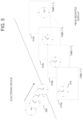
- FIG. 5 further illustrates aspects of providing an XR display according to various embodiments of this disclosure.
- the embodiment of the aspects of providing an XR display shown in FIG. 5 is for illustration only and other embodiments could be used without departing from the scope of the present disclosure.
- an electronic device renders pixels associated with image data to be presented at a later times (for example, at regular intervals beginning 100 milliseconds (ms) in the future) as a series of frames (for example, frames 510 a through 510 n ) on a display of the HMD.
- the rendered pixels 505 are transmitted from the electronic device over the link to the HMD, where the rendered pixels are incorporated into the series of frames ( 510 a - 510 n ) presented in succession at predetermined times (for example, times t 1 through t n ), to provide an XR display.
- the appearance of digital objects produced from rendered pixels 505 within an XR display is multiply dynamic in that the source image changes over time (for example, the positions of the hands of clock 515 change over frames 510 a through 510 n ).
- the appearance of digital objects in the XR display provided through the successive presentation of frames 510 a through 510 n is dynamic in the sense that the position and projection (for example, the viewing angle) of digital objects within the XR display changes in response to changes in the pose of the MID.
- the overall position of clock 515 moves within the space of the frame changes across frames 510 a through 510 n in response to changes in the pose of the MID.
- the changes in projection of digital objects within the constituent frames of an XR display in response to changes in pose is handled, in part or in whole, by one or more processors (for example, CPU 211 in FIG. 2 ) based on pose data obtained by one or more motion sensors (for example, IMU 215 in FIG. 2 ) of the HMD.
- processors for example, CPU 211 in FIG. 2
- pose data obtained by one or more motion sensors (for example, IMU 215 in FIG. 2 ) of the HMD.
- FIG. 6 is an example further illustrating aspects of providing an XR display at an HMD based on pixels passed over a data link from an electronic device according to various embodiments of this disclosure.
- the embodiment of the aspects of providing an XR display shown in FIG. 6 is for illustration only and other embodiments could be used without departing from the scope of the present disclosure.
- a first timeline 600 depicts a current time to which the other three timelines in FIG. 6 are synchronized.
- a second timeline 605 depicts activity intervals (i.e., time periods over which processes are performed) occurring at an HMD (for example, HMD 310 in FIG. 3 ).
- a third timeline 640 depicts activity intervals occurring at an electronic device (for example, electronic device 305 in FIG. 3 ).
- a fourth timeline 670 depicts the current pose (as expressed through the position of a user's head) of the HMD associated with second timeline 605 .
- the computational workload of providing a multiply dynamic XR display includes managing the computational load associated with reprojecting objects in the XR display due to pose changes occurring during the process of transmitting rendered pixels from the electronic device to the HMD.
- pixels are rendered at an electronic device at a first time, transmitted to the HMD, and at a second time, are adjusted for the current pose in advance of being displayed as part of an XR display provided by the MID.
- the interval between the first time, at which pixels for an XR display are rendered at an electronic device, and the second time, at which the pixels are available for pose adjustment in preparation for display presents a performance bottleneck for systems for providing an XR display across two computing platforms. Further, addressing the above-described performance bottleneck without adversely affecting (for example, by increasing battery consumption or diminishing resolution) remains a source of technical challenges and opportunities for improvement in the art.
- the electronic device receives a source image (for example, a vector representation of a scene) from an application supporting the XR display provided at the HMD.
- a source image for example, a vector representation of a scene
- the rendering device renders the source image as pixels for display at the MID.
- the rendering processes performed over interval 645 include, without limitation, shading and generating surface textures of digital objects appearing in the XR display provided at the MID.
- the pose coordinates for the companion display have values associated with a first pose 675 (represented in the figure by the head facing due north in the image).
- a pose can change between rendering a set of pixels for display and actually displaying them as part of a pose-adjusted XR display.
- interval 645 can vary based on a range of potentially interrelated variables, including without resolution, the frame-over-frame changes in the source images to be rendered, the desired resolution at the MID, and available system resources.
- Interval 645 concludes when a set of pixels associated with a particular frame (for example, frame 510 b in FIG. 5 ) to be displayed at the companion device at a predetermined point in time, as part of a predetermined sequence of frames are rendered, and need to be sent from the electronic device to the HMD.
- a particular frame for example, frame 510 b in FIG. 5
- Interval 645 concludes when a set of pixels associated with a particular frame (for example, frame 510 b in FIG. 5 ) to be displayed at the companion device at a predetermined point in time, as part of a predetermined sequence of frames are rendered, and need to be sent from the electronic device to the HMD.
- rendered pixels are encoded prior to transmission over an encoding interval 650 .
- the rendered pixels are compressed using one or more video compression algorithms (for example, x265 compression), to reduce the volume of bytes required to send the rendered pixels.
- the duration of encoding interval 650 can depend on a variety of interrelated factors, including, without limitation the amount of pixel data to be encoded, the available processor resources for encoding, and the tolerance of the XR system for latency between rendering and display. Additionally, in some embodiments, the encoding interval 650 may be temporarily or permanently avoided, as other factors, such as, for example, the available bandwidth in the link between the electronic device and UN/ID are such that it is more efficient not to compress pixels prior to transmission.
- the duration of interval overall, and relative to other intervals shown in the illustrative example of FIG. 6 depends on a number of potentially interrelated factors, including without limitation, the amount of data to be compressed, the desired resolution of an XR display, the time until display, and the compression algorithm used for encoding.
- pixels rendered over interval 645 and in certain embodiments, encoded over interval 650 are transmitted from the electronic device to the HMD over a data link (for example, link 315 ) over a transmission interval 655 .
- the pixels are transmitted according to one or more specified communication protocols, including, without limitation, BLUETOOTH, WI-FI, LTE or 5G protocols.
- the duration of transmission interval 655 in total, and relative to other intervals described with reference to the illustrative example of FIG. 6 can depend on a variety of potentially interrelated factors, including without limitation, the quality of the connection between the HMD and electronic device, system constraints on battery and processor resources for transmission, and the volume of pixel data to be transmitted from the electronic device to the HMD.
- transmission interval 655 concludes when all the pixels have been sent (or attempted to be sent) to the HMD.
- the pixels are encoded at the electronic device prior to transmission (for example, by compressing the pixel data using one or more compression algorithms)
- the pixels upon receipt at the HMD, the pixels are decoded in preparation for display over a decoding interval 660 , during which the HMD applies one or more decompression algorithms to restore the pixel data to a format suitable for pre-display correction.
- the duration of decoding interval 660 both in total, and relative to other intervals shown in FIG.
- the pose of the HMD has, during the time between the conclusion of rendering interval 645 and the conclusion of decoding interval 660 , shifted from a first pose 675 , through a second pose 677 , to a third pose 679 .
- the HMD's perspective of the live view has changed in the time between rendering a frame of pixels at the electronic device and receiving the pixels at the MID, such that, absent adjustment of the projection of the image data in the XR display, the mapping between digital objects embodied as rendered pixels and the live view of the physical world will be off due to the change in pose.
- the HMD reprojects, or warps (also referred to herein as a “reprojection warp” or an “image reproduction warp”) the pixels received from the electronic device, according to a changed coordinate system, reflecting the change in pose between over the interval between rendering at the electronic device and reception at the HMD.
- warps also referred to herein as a “reprojection warp” or an “image reproduction warp”
- the perspective of the digital object defined by the rendered pixels within the XR display is adjusted to reflect the change in pose of the HMD.
- algorithms for reprojecting the rendered pixels include, without limitation, the gdalwarp utility of the Geospatial Data Abstraction Library (“GDAL”).
- the duration of adjustment interval 661 depends on a number of potentially interrelated factors, including, without limitation, the extent to which the pose of the HMD has changed over the interval between rendering and reception at the HMD, the resolution of the XR display utilizing the received pixels, and the processing resources of the MID.
- adjustment interval 661 concludes when the received pixels are reprojected according to a shifted coordinate system to account for the change from first pose 675 to third pose 679 .
- the rendered and corrected pixels are displayed as a frame of an XR display over a display interval 663 .
- the duration of display interval 663 depends on a current frame rate of the XR display provided at the HMD.
- the frame rate at the HMD depends, at least in part, on the speed with which the electronic device can provide correction-ready pixels to the MID.
- the interval 665 between the end of rendering interval 645 and the start of adjustment interval 661 represents, for certain embodiments, a performance bottleneck for providing an XR display at a HMD based on pixels rendered at an electronic device. For example, the longer the interval 665 becomes, the greater the opportunity for the pose of the HMD to change becomes, and the more processing to reproject the image to account for the changed pose needs to be performed at the HMD.
- the overall performance of an XR system comprises a variety of interrelated dimensions, including, without limitation, system cost, frame rate of an XR display, resolution of the XR display, battery life, processor consumption and heat generated at the HMD. While interval 665 could, potentially, be shortened by providing one or both of the electronic device or HMD with processing greater resources for compression or decompression, such a change would foreseeably come at the cost of enhanced battery consumption (for example, from a more powerful processor), or less processing resources available for other system processes. Similarly, the time associated with compressing and transmitting full frames of video data can be reduced by lowering the resolution of the XR display provided at the MID, but this approach necessarily diminishes the quality of the digital objects at the display.
- FIGS. 7 A and 7 B illustrate, in block diagram format, examples architectures for reducing a data communication load through lossless data reduction according to various embodiments of this disclosure.
- elements common to both the example of FIG. 7 A and FIG. 7 B are numbered similarly.
- the embodiments shown in FIGS. 7 A and 7 B are for illustration only. Other embodiments could be used without departing from the scope of the present disclosure.
- the architecture comprises an electronic device 701 (for example, device 100 in FIG. 1 ), which is communicatively linked (for example, via a link (for example, link 315 ) to a HMD 751 (for example, HMD 405 in FIG. 4 )).
- an electronic device 701 for example, device 100 in FIG. 1
- a link for example, link 315
- HMD 751 for example, HMD 405 in FIG. 4
- the process for rendering a frame in a sequence of frames (for example, frames 510 a through 510 n in FIG. 5 ) to be presented as an XR display at a HMD begins when a source image 705 is passed to a rendering engine 710 executing on the electronic device 701 .
- source image 705 corresponds to image data (for example, vector or other non-pixel level) generated by an application supporting an XR display, which corresponds to a frame to be rendered at the electronic device and then sent to the HMD for viewing.
- source image 705 corresponds to the nth frame in a sequence of frames, with the n ⁇ 1th frame corresponding to the immediately preceding frame, and the n+1th frame corresponding to the frame after the nth frame.
- the rendering engine 710 comprises an application or process executing on electronic device 701 for rendering scene-level data output by an application as pixels for display.
- Examples of graphics pipelines which can operate as rendering engine 710 include, without limitation, the OpenGL Rendering Pipeline for ANDROID® devices and the Metal Graphics Pipeline for iOS devices.
- rendering engine 710 determines shading values and textures for content appearing as digital objects in the XR display presented at HMD 751 .
- the rendering engine 710 outputs a new frame 715 based on source image 705 .
- new frame 715 is the nth frame in a sequence of frames rendered by electronic device 701 for transmission to, and projection at HMD 751 .
- the content of the new frame 715 is rendered to present digital objects from a vantage point based on a known or predicted pose of the HMD.
- pose information (for example, time-stamped IMU data, or a prediction of the HAMID's pose at a given time) is obtained from one or more sensors (for example, IMU 215 in FIG. 2 ) of the HMD via a data link connecting the electronic device and HMD.
- the electronic device performs a difference operation between new frame 715 and a reference frame 725 stored in a memory of the electronic device.
- the difference operation performed at block 720 identifies pixels unique to new frame 715 .
- the reference frame 725 comprises a copy of the previous (or n ⁇ 1th frame) rendered by rendering engine 710 , based on source image data generated prior to source image 705 .
- electronic device 701 generates, based on the difference operation performed at block 720 , a differential frame 735 comprising pixels unique to new frame 715 .
- a differential frame 735 comprising pixels unique to new frame 715 .
- the frame-over-frame differences between frames decrease as the length of the interval between frames decreases.
- a significant portion of the pixels of a given frame are likely to be the same as the pixels of the previous frame.
- a differential frame comprising the difference (or just the changes) between new frame 715 and reference frame 725 is generated.
- the relationship between the reference frame, the differential frame and the new frame can be expressed by the following equations: Frame(new) Frame(ref) Frame(diff) (1) Frame(diff) Frame(ref) Frame(new) (2)
- the content of a differential frame comprises the set of pixels of a new frame (Frame(new)), from which the pixels common to a reference frame (Frame(ref)) have been subtracted out, to leave only the subset of pixels of the new frame which are unique to the new frame.
- the new frame (Frame(new)) can be reconstituted by combining the pixels of the reference frame with those unique to the differential frame (Frame(diff)) with those of a reference frame.
- the image data for a new (n+1th) frame can be provided, without loss of data, from electronic device 701 to HMD 751 by sending only a differential frame, rather than a complete frame.
- the amount of data to be sent over the link between electronic device 701 and HMD 751 can be reduced, thereby reducing the length of the time (for example, interval 665 in FIG. 6 ) between rendering at the electronic device and reception at the HMD.
- electronic device 701 provides HMD 751 with a reduced set of pixels (i.e., differential frame 735 ), as compared to a full frame, thereby reducing the communication load between electronic device 701 and HMD 751 without a loss of image data.
- a reduced set of pixels i.e., differential frame 735
- embodiments according to the example of FIG. 7 A can improve the overall performance of electronic device 701 and HMD 751 as a system for providing an XR display without negatively affecting any other dimensions of system performance, such as battery life or hardware requirements.
- the differential frame 735 is encoded at block 740 , to reduce the data size and allow for faster transmission.
- the differential frame is encoded using one of a plurality of possible encoding modes.
- the encoding modes include, without, different (or no) compression algorithms, or different quality/speed presets for a given compression algorithm.
- the x.265 compression algorithm provides ten compression speed presets, ranging from “ultrafast” to “placebo.”
- each of these presets may comprise a compression mode.
- the encoding mode of the plurality of encoding modes is selected based on a contextual factor, such as the size of the differential frame, or head pose data received from the HMD.
- the electronic device 701 transmits the differential frame to HMD 751 via one or more communication links (for example, link 315 in FIG. 3 ).
- the HMD 751 receives the differential frame, via the link from electronic device 701 , and differential frame 759 is available for further processing at HMD 751 .
- the differential frame has been previously encoded (for example, at block 740 , the differential frame is decoded such that an uncompressed differential frame 759 from which new frame 715 can be reconstituted at HMD 751 is available).
- the HMD 751 obtains, from a memory of the device, a reference frame 761 .
- reference frame 761 comprises an HMD device copy of reference frame 725 .
- HMD 751 reconstitutes new frame 715 by combining reference frame 761 with differential frame 759 , according to Equation 2 herein.
- the pixels unique to the new frame 715 provided in differential frame 759 replace certain pixels of the reference frame 761 , thereby updating the frame.
- the new frame generated at block 763 is stored in a memory of the HMD as a reference frame.
- one or more sensors of the HMD obtain tracking measurements associated with the pose of the HMD at a time subsequent to generation of new frame 715 at electronic device 701 .
- the tracking measurements obtained at block 765 are, as necessary, processed as head pose data 767 .
- the head pose data 767 comprises time-stamped data associated with a recorded pose of the HMD.
- the head pose data 767 comprises a predicted head pose of the HMD at a future time.
- head pose data 767 is transmitted from HMD 751 to electronic device 701 .
- the head pose data is provided to rendering engine 710 to provide updated perspective information for rendering subsequent source image.
- an image reproduction warp of the reconstituted new frame based on head pose data 767 is performed at block 769 , thereby updating the projection of new frame 715 based on the most recent available head pose data.
- the most recent available head pose data (in this case, head pose data 767 ) is, in some embodiments also transmitted back to electronic device 701 , where it can be used, for example, to improve the recency of the perspective information used by rendering engine 710 in generating the next frame to be transmitted to HMD 751 .
- the image reprojection warp performed at block 769 produces a pose-adjusted new frame 771 .
- the pose-adjusted new frame 771 is further corrected at block 773 .
- the further corrections performed at block 773 comprise correcting for distortions produced during the image reproduction warp, and removing artifacts from the reprojected frame prior to display.
- the pose-adjusted new frame is displayed by the head mounted display for a predetermined time (for example, 1/60 th of a second, in embodiments with a 60 frame-per-second frame rate) as one frame of a sequence of frames providing an XR display at the HMD.
- a predetermined time for example, 1/60 th of a second, in embodiments with a 60 frame-per-second frame rate
- FIG. 7 B illustrates, in block diagram format, another example of an architecture for reducing a data communication load through lossless data reduction according to certain embodiments of this disclosure. As previously noted, blocks and elements common to FIGS. 7 A and 7 B are numbered similarly.
- the performance of electronic device 701 and HMD 751 can be enhanced by improving the recency of the differential frame relative to the time of display, so that there is less opportunity for changes in head pose, and by implication, potentially less processing at HMD 751 to adjust for intervening change in head poses.
- the overall performance of electronic device 701 and HMD 751 as a system for providing an XR display can be improved without compromising other dimensions of the system's performance.
- an image reprojection warp 730 is performed on reference frame 725 , based on pose data provided by the HMD.
- the pose data provided by the HMD is the same pose data used by the HMD to adjust the projection of the n ⁇ 1th frame prior to display.
- the pose data provided by the HMD is a predicted pose for a point in time between rendering of the reference frame and the new frame.
- the frame-over-frame differences decreases as the interval between the times with which the frames are associated with decreases.
- the image reprojection warp 730 “updates” the pixels of reference frame 725 to account for pose changes subsequent to rendering.
- image reprojection warp 730 “moves up” the time with which reference frame 725 is associated to the time of the pose data used to perform image reprojection warp 730 .
- a difference operation is performed between new frame 715 , and the reference frame, as updated image reprojection warp 730 to identify pixels unique to new frame 715 .
- the updated reference frame is stored in a memory of electronic device 701 as a reference frame.
- the “quality” in terms of recency and degree of adjustment to match a current pose at the MID) of the pixels of the differential frame can be improved.
- FIG. 8 illustrates aspects of an example of a process 800 for reducing a data communication load through lossless data reduction according to certain embodiments of this disclosure. While the flow chart depicts a series of sequential steps, unless explicitly stated, no inference should be drawn from that sequence regarding specific order of performance, performance of steps or portions thereof serially rather than concurrently or in an overlapping manner, or performance of the steps depicted exclusively without the occurrence of intervening or intermediate steps.
- the process depicted in the example depicted is implemented by respective processors in, for example, an electronic device and an MID.
- process 800 are practiced on two computing platforms, in this case, an electronic device 801 (for example, electronic device 100 in FIG. 1 ), and a head mounted display (TIMID) 851 (for example, HMD 405 in FIG. 4 , or HMD 751 in FIG. 7 A ) communicatively connected over a link (for example, a WI-FI or BLUETOOTH connection).
- a link for example, a WI-FI or BLUETOOTH connection
- HMD 851 generates pose data (p x ) associated with the current pose of the apparatus.
- pose data (p x ) comprises predicted pose data associated with a future time.
- pose data (p x ) comprises data output by one or more sensors of the HMD, such as an accelerometer, IMU or internal gyro associated with a particular time value.
- pose data (p x ) is sent from HMD 851 to electronic device 801 , for, without limitation, updating a reference frame in preparation for generating a differential frame to be subsequently provided to HMD 851 .
- pose data (p x ) is used to perform an image reproduction warp of a previously reconstituted frame (f n-1 ), to adjust for changes in HMD pose arising during the time between the time frame (f n-1 ) was rendered and the present moment.
- frame (f n-1 ) is re-designated as frame (fw n ).
- frame (fw n ) is stored in a memory of HMD 851 as a reference frame.
- frame (fw n ) is displayed on HMD 851 as one frame of a sequence of frames comprising an XR display provided at HMD 851 .
- certain embodiments according to this disclosure provide the dual technical benefits of reducing the load on the link (for example, link 315 in FIG. 3 ) connecting the electronic device 801 and the UN/ID 851 , while at the same time, improving the quality (in terms of both the recency of the pixels provided, and avoiding data loss through compression) of the pixels provided to the HMD.
- these technical benefits are provided by, without limitation, sending differential frames from the electronic device 801 to the UN/ID 851 , and improving the recency of the differential frames by sending pose data from the HMD 851 to electronic device 801 .
- pixels rendered at the electronic device 801 are rendered based on more recent head pose data, thereby reducing the frame-over-frame difference between a frame as rendered and the frame as adjusted by an image reproduction warp to account for subsequent changes in head pose.
- the electronic device 801 begins the process of generating a differential frame to be transmitted to UN/D 851 , by obtaining a previous frame (f n-1 ) from a memory of electronic device 801 .
- previous frame (f n-1 ) is associated with an earlier time than pose data (p X ).
- electronic device receives pose data (p X ) from HMD 851 at block 830 .
- electronic device 801 performs an image reproduction warp of previous frame (f n-1 ) based on pose data pose data (p X ) to produce a copy of (fw n ) at electronic device 801 , which, in this illustrative example, is associated with the same time as pose data (p X ), which is more recent than previous frame (f n-1 ).
- electronic device 801 renders a new frame (f n ), comprising the underlying image data of a pose-adjusted frame to be displayed on the HMD subsequent to frame (fw n ) as part of a sequence of frames providing an XR display.
- electronic device sends differential frame (fd n ) to HMD 851 , and differential frame (fd n ) is received at HMD 851 at operation 860 .
- new frame (f n ) is reconstituted as fw n +fd n , and process 800 is reiterated with new pose data.
- FIG. 9 illustrates aspects of the technical benefits realized by certain embodiments of this disclosure.
- the examples shown in FIG. 9 are for illustration only and other examples could be used without departing from the scope of the present disclosure.
- the electronic device sends the UN/ID differential frames (as opposed to full frames)
- the HMD sends the electronic device pose data.
- the volume of data sent from the HMD is reduced relative to sending full frames of image data.
- sending pose data from the HMD to the electronic device improves the recency of differential frames output by the electronic device.
- an image reprojection warp for example, image reprojection warp 730 in FIG.
- the pose data (for example, pose data 767 ) can, in certain embodiments, be provided to a rendering engine (for example, rendering engine 710 ) to perform the pose adjustments (for example, a three-dimensional rotation or translation of the image) at the rendering stage.
- a rendering engine for example, rendering engine 710
- the pose adjustments for example, a three-dimensional rotation or translation of the image
- new frame 901 comprises a new frame of digital content for an XR display prior to any correction for head pose performed by the rendering engine (for example, rendering engine 710 in FIG. 7 A ) based on recent head pose data (for example, head pose data 767 in FIG. 7 A ) from the HMD.
- the rendering engine for example, rendering engine 710 in FIG. 7 A
- recent head pose data for example, head pose data 767 in FIG. 7 A
- the frame 903 shows the new frame as output from a rendering engine or graphics pipeline that did not perform any adjustment of the rendered image to conform the perspective of the rendered image to the most recent available pose data.
- box 905 shows the superposition of uncorrected frame 903 relative to a frame 907 following a pose adjustment (for example, adjusted new frame 771 in FIG. 7 A ) performed at the HMD.
- a pose adjustment for example, adjusted new frame 771 in FIG. 7 A
- a visible shift between frames 903 and 907 is present.
- 71% of the pixels of the originally rendered frame 903 map to pixels of HMD pose-adjusted frame 907 .
- FIG. 9 An example of a frame 909 in which new frame 901 has been adjusted at the electronic device to account for the most recent pose data provided by the UN/ID to the electronic device is shown at the bottom center of FIG. 9 .
- the box 911 shows the superposition of uncorrected frame 903 relative to the HMD pose-adjusted frame 907 .
- the two frames are in closer spatial alignment than the example shown in the box 905 .
- 85% of the pixels of pose-adjusted frame 909 map to pixels of HMD pose-adjusted frame 907 .
- the above-described improvement in correspondence between the frame provided by the electronic device and the frame as corrected at the HMD translates into a reduction in the computational work required of the HMD, and an overall improvement in the performance of the electronic device-TIMID pair as a system for providing an XR display.
- FIG. 10 A illustrates an example of operations of a method 1000 for reducing a communication load through lossless data reduction according to certain embodiments of this disclosure.
- the operations of method 1000 are performed at a single computing platform (for example, electronic device 100 in FIG. 1 ) communicatively connected to an HMD (for example, HMD 751 in FIGS. 7 A and 7 B ).
- HMD for example, HMD 751 in FIGS. 7 A and 7 B
- the flow chart depicts a series of sequential steps, unless explicitly stated, no inference should be drawn from that sequence regarding specific order of performance, performance of steps or portions thereof serially rather than concurrently or in an overlapping manner, or performance of the steps depicted exclusively without the occurrence of intervening or intermediate steps.
- the process depicted in the example depicted is implemented by a processor in, for example, an HMD.
- the electronic device obtains a first reference frame (for example, reference frame 725 in FIG. 7 A ) comprising a first set of pixels associated with a first time.
- a first reference frame for example, reference frame 725 in FIG. 7 A
- the electronic device renders a source image as a new frame (for example, the new frame generated at operation 840 in FIG. 8 or new frame 715 in FIG. 7 A ), wherein the new frame comprises a second set of pixels associated with a display to be provided by the HMD at a second time subsequent to the first time.
- the pixels of the new frame are reprojected to account for one or more intervening changes in pose between rendering and display at the HMD.
- the electronic device generates a differential frame (for example, differential frame 735 in FIG. 7 A or the differential frame generated at operation 845 in FIG. 8 ) based on a difference operation between the reference frame and the new frame to identify pixels of the new frame which are unique to the new frame.
- a differential frame for example, differential frame 735 in FIG. 7 A or the differential frame generated at operation 845 in FIG. 8
- the differential frame is sent from the electronic device to the HMD over a link (for example, link 315 in FIG. 3 ) connecting the two devices.
- the new frame is stored in the memory of the electronic device as a second reference frame.
- FIG. 10 B illustrates further operations of methods for reducing a communication load through lossless data reduction according to certain embodiments of this disclosure.
- the operations described with reference to FIG. 10 B are, in certain embodiments, incorporated into the method 1000 described in FIG. 10 A . While the flow chart depicts a series of sequential steps, unless explicitly stated, no inference should be drawn from that sequence regarding specific order of performance, performance of steps or portions thereof serially rather than concurrently or in an overlapping manner, or performance of the steps depicted exclusively without the occurrence of intervening or intermediate steps.
- the process depicted in the example depicted is implemented by a processor in, for example, an MID.
- an electronic device performs, as part of the rendering process, a three-dimensional rotation or translation of a source image to “pre-adjust” the rendered image to recent head pose data. As shown through the example of FIG. 9 , such adjustments during the rendering stage can reduce the computational load at an HMD.
- the electronic device receives head pose data (for example, head pose data 767 in FIGS. 7 A and 7 B ) from the HMD.
- the received head pose data comprises the output of one or more pose tracking sensors of the MID, or a prediction as to the HMD's pose at a future point in time.
- the electronic device performs a three-dimensional rotation or translation of the source data based on the head pose data received at operation 1055 as part of a rendering process (for example, a process performed by rendering engine 710 in FIGS. 7 A and 7 B ) performed at the electronic device.
- a rendering process for example, a process performed by rendering engine 710 in FIGS. 7 A and 7 B
- the electronic device updates a reference frame prior to generating a differential frame to improve the recency of the reference frame, and by implication, to reduce the amount of correction for intervening pose changes which needs to be carried out the HMD.
- FIG. 10 C illustrates another example of further operations of methods for reducing a communication load through lossless data reduction according to certain embodiments of this disclosure.
- the further operations described with reference to FIGS. 10 B- 10 D can, in embodiments according to this disclosure be variously combined, either singly, or in combination, with methods for reducing communication load (for example, method 1000 in FIG. 10 A ).
- the electronic device receives, via the link connecting it to the HMD, head pose data (for example, head pose data generated at block 805 in FIG. 8 ) from the MID.
- the electronic device updates the first reference frame prior to generating the differential frame by performing an image reprojection warp (for example, image reprojection warp 730 in FIG. 7 B ) on the reference frame.
- FIG. 10 D illustrates another example of further operations of methods for reducing a communication load through lossless data reduction according to certain embodiments of this disclosure.
- the further operations described with reference to FIGS. 10 B- 10 D can, in embodiments according to this disclosure be variously combined, either singly, or in combination, with methods for reducing communication load (for example, method 1000 in FIG. 10 A ).
- the electronic device selectively encodes differential frames based on factors such as the size of the differential frame to conserve resources and improve the efficiency of the system overall. For example, in cases where a differential frame contains little data, it may be more efficient to send the differential frame to the HMD, rather than encode and decode the data. Accordingly, in some embodiments, at operation 1075 , the electronic device selects an encoding mode from a plurality of encoding modes for transmitting the differential frame, wherein the plurality of encoding modes can include not encoding the differential frame. Further, at operation 1080 , the electronic device encodes the differential frame according to the selected encoding mode.
- FIG. 11 A illustrates an example of a process 1100 for reducing a communication load through lossless data reduction according to certain embodiments of this disclosure.
- the operations of process 1100 are performed at an HMD (for example, HMD 405 in FIG. 4 ) communicatively connected to an electronic device.
- HMD for example, HMD 405 in FIG. 4
- the flow chart depicts a series of sequential steps, unless explicitly stated, no inference should be drawn from that sequence regarding specific order of performance, performance of steps or portions thereof serially rather than concurrently or in an overlapping manner, or performance of the steps depicted exclusively without the occurrence of intervening or intermediate steps.
- the process depicted in the example depicted is implemented by a processor in, for example, an HMD.
- the HMD receives a differential frame from an electronic device, wherein the differential frame comprises pixels unique to a new frame to be displayed at the HMD.
- the HMD obtains a first reference frame (for example, reference frame 761 in FIG. 7 A ) from a memory (for example, memory 213 ) of the HMD.
- the first reference frame comprises a pose-adjusted frame previously received from the electronic device.
- the HMD obtains head pose data (for example, pose data (p x ) in FIG. 8 ) from one or more sensors (for example, IMU 215 in FIG. 2 ) of the MID.
- head pose data for example, pose data (p x ) in FIG. 8
- sensors for example, IMU 215 in FIG. 2
- the HMD generates (for example, as shown in block 763 of FIG. 7 A ), or reconstitutes a new frame by combining the differential frame and the reference frame, by applying the relationship described by Equation 2 herein.
- the HMD performs an image reprojection warp (for example, the image reprojection warp at block 769 in FIG. 7 A or block 815 in FIG. 8 ) based on the head pose data obtained at operation 1115 , thereby adjusting the new image according to the current head pose data.
- an image reprojection warp for example, the image reprojection warp at block 769 in FIG. 7 A or block 815 in FIG. 8 .
- the HMD outputs the pose-adjusted new frame to a display (for example, display 207 in FIG. 2 ) of the MID.
- FIG. 11 B illustrates examples of further operations of methods (for example, process 1100 in FIG. 11 A ) for reducing a communication load through lossless data reduction according to certain embodiments of this disclosure.
- the further operations described in the examples of FIGS. 11 B and 11 C can, according to various embodiments, be variously combined, both singly and in combination with methods for reducing a communication load according to certain embodiments of this disclosure.
- the described operations are performed at a HMD (for example, HMD 851 in FIG. 8 ).
- the HMD sends head pose data (for example, head pose data 767 in FIG. 7 B ) to the electronic device via the link.
- head pose data for example, head pose data 767 in FIG. 7 B
- the HMD subsequent to performing an image reprojection warp of the new frame to adjust the frame for data associated with the current pose of the HMD (for example, the image reprojection warp performed at block 815 in FIG. 8 ), stores the pose-adjusted new frame (for example, new frame 771 in FIG. 7 A ) as a reference frame.
- the pose-adjusted new frame for example, new frame 771 in FIG. 7 A
- FIG. 11 C illustrates an example of further operations performed at an HMD according to various embodiments of this disclosure.
- the HMD identifies an encoding mode applied to a differential frame received from the electronic device, and at operation 1165 , decodes the encoded differential frame according to the identified encoding mode.
Landscapes
- Engineering & Computer Science (AREA)
- Physics & Mathematics (AREA)
- General Physics & Mathematics (AREA)
- Theoretical Computer Science (AREA)
- General Engineering & Computer Science (AREA)
- Multimedia (AREA)
- Signal Processing (AREA)
- Optics & Photonics (AREA)
- Human Computer Interaction (AREA)
- Computer Graphics (AREA)
- Architecture (AREA)
- Computer Hardware Design (AREA)
- Software Systems (AREA)
- User Interface Of Digital Computer (AREA)
- Algebra (AREA)
- Mathematical Analysis (AREA)
- Mathematical Optimization (AREA)
- Mathematical Physics (AREA)
- Pure & Applied Mathematics (AREA)
- Controls And Circuits For Display Device (AREA)
Abstract
Description
Frame(new) Frame(ref) Frame(diff) (1)
Frame(diff) Frame(ref) Frame(new) (2)
Claims (27)
Priority Applications (3)
| Application Number | Priority Date | Filing Date | Title |
|---|---|---|---|
| US16/990,779 US12332437B2 (en) | 2020-04-07 | 2020-08-11 | System and method for reducing image data throughput to head mounted display |
| KR1020200139420A KR20210125403A (en) | 2020-04-07 | 2020-10-26 | Method for reducing communication load through lossless data reduction, apparatus and storage medium |
| PCT/KR2020/015748 WO2021206251A1 (en) | 2020-04-07 | 2020-11-11 | System and method for reduced communication load through lossless data reduction |
Applications Claiming Priority (2)
| Application Number | Priority Date | Filing Date | Title |
|---|---|---|---|
| US202063006490P | 2020-04-07 | 2020-04-07 | |
| US16/990,779 US12332437B2 (en) | 2020-04-07 | 2020-08-11 | System and method for reducing image data throughput to head mounted display |
Publications (2)
| Publication Number | Publication Date |
|---|---|
| US20210311307A1 US20210311307A1 (en) | 2021-10-07 |
| US12332437B2 true US12332437B2 (en) | 2025-06-17 |
Family
ID=77921938
Family Applications (1)
| Application Number | Title | Priority Date | Filing Date |
|---|---|---|---|
| US16/990,779 Active 2041-08-10 US12332437B2 (en) | 2020-04-07 | 2020-08-11 | System and method for reducing image data throughput to head mounted display |
Country Status (2)
| Country | Link |
|---|---|
| US (1) | US12332437B2 (en) |
| KR (1) | KR20210125403A (en) |
Families Citing this family (4)
| Publication number | Priority date | Publication date | Assignee | Title |
|---|---|---|---|---|
| GB202012559D0 (en) | 2020-08-12 | 2020-09-23 | Samsung Electronics Co Ltd | Reducing latency between receiving user input and displaying resulting frame |
| US12347060B2 (en) * | 2022-07-27 | 2025-07-01 | Rockwell Collins, Inc. | Head-frame symbology isolation for head worn display (HWD) |
| US20240056563A1 (en) * | 2022-08-12 | 2024-02-15 | Apple Inc. | Transparent Display with Blur Effect for Physical Objects |
| US20260024274A1 (en) * | 2024-07-17 | 2026-01-22 | Samsung Electronics Co., Ltd. | Depth-based reprojection with adaptive depth densification and super-resolution for video see-through (vst) extended reality (xr) or other applications |
Citations (19)
| Publication number | Priority date | Publication date | Assignee | Title |
|---|---|---|---|---|
| US6212236B1 (en) | 1997-03-26 | 2001-04-03 | Matsushita Electric Industrial Co., Ltd. | Image decoding apparatus |
| US20030063043A1 (en) * | 2001-09-28 | 2003-04-03 | Girard Luke E. | Method and apparatus for wireless headset video interface |
| US20120121163A1 (en) | 2010-11-15 | 2012-05-17 | Samsung Electronics Co., Ltd. | 3d display apparatus and method for extracting depth of 3d image thereof |
| US20130002839A1 (en) | 2010-01-07 | 2013-01-03 | 3Dswitch S.R.L. | Device and Method for the Recognition of Glasses for Stereoscopic Vision, and Related Method to Control the Display of a Stereoscopic Video Stream |
| US20130148740A1 (en) | 2011-12-09 | 2013-06-13 | Qualcomm Incorporated | Method and apparatus for processing partial video frame data |
| US20150379772A1 (en) | 2014-06-30 | 2015-12-31 | Samsung Display Co., Ltd. | Tracking accelerator for virtual and augmented reality displays |
| KR101583598B1 (en) | 2014-08-25 | 2016-01-08 | 태성전설 주식회사 | Camera, service server, system and method for processing high-resolution image |
| US20170045941A1 (en) | 2011-08-12 | 2017-02-16 | Sony Interactive Entertainment Inc. | Wireless Head Mounted Display with Differential Rendering and Sound Localization |
| US20170256240A1 (en) | 2016-03-06 | 2017-09-07 | Htc Corporation | Interactive display system and method |
| US9881421B2 (en) | 2014-07-29 | 2018-01-30 | Sony Interactive Entertainment Europe Limited | Image processing |
| US20180047332A1 (en) * | 2016-08-12 | 2018-02-15 | Intel Corporation | Optimized Display Image Rendering |
| US20190058859A1 (en) | 2017-08-17 | 2019-02-21 | Microsoft Technology Licensing, Llc | Localized depth map generation |
| US20190147612A1 (en) * | 2016-04-21 | 2019-05-16 | Interdigital Ce Patent Holdings | Method and apparatus for estimating a pose of a rendering device |
| US10317991B2 (en) | 2016-02-09 | 2019-06-11 | Google Llc | Pixel adjusting at display controller for electronic display stabilization |
| US20190213975A1 (en) | 2016-09-08 | 2019-07-11 | Sony Interactive Entertainment Inc. | Image processing system, image processing method, and computer program |
| US20200026349A1 (en) * | 2018-07-19 | 2020-01-23 | Samsung Electronics Co., Ltd | System and method for hybrid eye tracker |
| KR20200030844A (en) | 2018-09-13 | 2020-03-23 | 엘지디스플레이 주식회사 | Display device and head mounted device including thereof |
| US20200098186A1 (en) * | 2018-09-17 | 2020-03-26 | Qualcomm Incorporated | Cross layer traffic optimization for split vr |
| US20200122641A1 (en) | 2018-10-22 | 2020-04-23 | Ahmad abo Alsheghri | Magic glasses |
-
2020
- 2020-08-11 US US16/990,779 patent/US12332437B2/en active Active
- 2020-10-26 KR KR1020200139420A patent/KR20210125403A/en active Pending
Patent Citations (19)
| Publication number | Priority date | Publication date | Assignee | Title |
|---|---|---|---|---|
| US6212236B1 (en) | 1997-03-26 | 2001-04-03 | Matsushita Electric Industrial Co., Ltd. | Image decoding apparatus |
| US20030063043A1 (en) * | 2001-09-28 | 2003-04-03 | Girard Luke E. | Method and apparatus for wireless headset video interface |
| US20130002839A1 (en) | 2010-01-07 | 2013-01-03 | 3Dswitch S.R.L. | Device and Method for the Recognition of Glasses for Stereoscopic Vision, and Related Method to Control the Display of a Stereoscopic Video Stream |
| US20120121163A1 (en) | 2010-11-15 | 2012-05-17 | Samsung Electronics Co., Ltd. | 3d display apparatus and method for extracting depth of 3d image thereof |
| US20170045941A1 (en) | 2011-08-12 | 2017-02-16 | Sony Interactive Entertainment Inc. | Wireless Head Mounted Display with Differential Rendering and Sound Localization |
| US20130148740A1 (en) | 2011-12-09 | 2013-06-13 | Qualcomm Incorporated | Method and apparatus for processing partial video frame data |
| US20150379772A1 (en) | 2014-06-30 | 2015-12-31 | Samsung Display Co., Ltd. | Tracking accelerator for virtual and augmented reality displays |
| US9881421B2 (en) | 2014-07-29 | 2018-01-30 | Sony Interactive Entertainment Europe Limited | Image processing |
| KR101583598B1 (en) | 2014-08-25 | 2016-01-08 | 태성전설 주식회사 | Camera, service server, system and method for processing high-resolution image |
| US10317991B2 (en) | 2016-02-09 | 2019-06-11 | Google Llc | Pixel adjusting at display controller for electronic display stabilization |
| US20170256240A1 (en) | 2016-03-06 | 2017-09-07 | Htc Corporation | Interactive display system and method |
| US20190147612A1 (en) * | 2016-04-21 | 2019-05-16 | Interdigital Ce Patent Holdings | Method and apparatus for estimating a pose of a rendering device |
| US20180047332A1 (en) * | 2016-08-12 | 2018-02-15 | Intel Corporation | Optimized Display Image Rendering |
| US20190213975A1 (en) | 2016-09-08 | 2019-07-11 | Sony Interactive Entertainment Inc. | Image processing system, image processing method, and computer program |
| US20190058859A1 (en) | 2017-08-17 | 2019-02-21 | Microsoft Technology Licensing, Llc | Localized depth map generation |
| US20200026349A1 (en) * | 2018-07-19 | 2020-01-23 | Samsung Electronics Co., Ltd | System and method for hybrid eye tracker |
| KR20200030844A (en) | 2018-09-13 | 2020-03-23 | 엘지디스플레이 주식회사 | Display device and head mounted device including thereof |
| US20200098186A1 (en) * | 2018-09-17 | 2020-03-26 | Qualcomm Incorporated | Cross layer traffic optimization for split vr |
| US20200122641A1 (en) | 2018-10-22 | 2020-04-23 | Ahmad abo Alsheghri | Magic glasses |
Non-Patent Citations (3)
| Title |
|---|
| International Search Report of the International Searching Authority dated Feb. 15, 2021 in connection with International Application No. PCT/KR2020/015748, 4 pages. |
| Request for the Submission of an Opinion dated Jan. 13, 2025 in connection with Korean Patent Application No. 10-2020-0139420, 18 pages. |
| Written Opinion of the International Searching Authority dated Feb. 15, 2021 in connection with International Application No. PCT/KR2020/015748, 5 pages. |
Also Published As
| Publication number | Publication date |
|---|---|
| KR20210125403A (en) | 2021-10-18 |
| US20210311307A1 (en) | 2021-10-07 |
Similar Documents
| Publication | Publication Date | Title |
|---|---|---|
| US12332437B2 (en) | System and method for reducing image data throughput to head mounted display | |
| EP3695383B1 (en) | Method and apparatus for rendering three-dimensional content | |
| US11514613B2 (en) | Point cloud and mesh compression using image/video codecs | |
| US12217368B2 (en) | Extended field of view generation for split-rendering for virtual reality streaming | |
| KR102474088B1 (en) | Method and device for compositing an image | |
| CN112673642A (en) | Cross-layer traffic optimization for split XR | |
| US20140092439A1 (en) | Encoding images using a 3d mesh of polygons and corresponding textures | |
| KR20220138403A (en) | Motion Smoothing in Distributed Systems | |
| CN110537208B (en) | Head mounted displays and methods | |
| US12212705B2 (en) | Controlling an augmented call based on user gaze | |
| US20210358158A1 (en) | System and method for depth map recovery | |
| US20200168001A1 (en) | Display unit for ar/vr/mr systems | |
| US20240205294A1 (en) | Resilient rendering for augmented-reality devices | |
| CN118365835A (en) | Method, device, electronic device and storage medium for rendering image | |
| US20190310818A1 (en) | Selective execution of warping for graphics processing | |
| WO2021249562A1 (en) | Information transmission method, related device, and system | |
| CN114860062A (en) | Image display method and device, readable medium and electronic equipment | |
| US20240371043A1 (en) | Processing image data in an extended-reality system | |
| WO2024249162A1 (en) | Rendering layers with different perception quality | |
| WO2021206251A1 (en) | System and method for reduced communication load through lossless data reduction | |
| EP3958574A1 (en) | Method and system for rendering virtual environment | |
| US20250308044A1 (en) | Mask based image composition | |
| US12536706B2 (en) | Dual detail video encoding with region specific quality control | |
| WO2024233009A1 (en) | Adaptive workload balancing for split extended reality (xr) systems | |
| JP2026510992A (en) | Method and system for dynamic depth-based reprojection |
Legal Events
| Date | Code | Title | Description |
|---|---|---|---|
| AS | Assignment |
Owner name: SAMSUNG ELECTRONICS CO., LTD., KOREA, REPUBLIC OF Free format text: ASSIGNMENT OF ASSIGNORS INTEREST;ASSIGNORS:PERI, CHRISTOPHER A., DR.;XIONG, YINGEN, DR.;LUO, LU, DR.;SIGNING DATES FROM 20200804 TO 20200810;REEL/FRAME:053461/0922 |
|
| FEPP | Fee payment procedure |
Free format text: ENTITY STATUS SET TO UNDISCOUNTED (ORIGINAL EVENT CODE: BIG.); ENTITY STATUS OF PATENT OWNER: LARGE ENTITY |
|
| STPP | Information on status: patent application and granting procedure in general |
Free format text: NON FINAL ACTION MAILED |
|
| STPP | Information on status: patent application and granting procedure in general |
Free format text: RESPONSE TO NON-FINAL OFFICE ACTION ENTERED AND FORWARDED TO EXAMINER |
|
| STPP | Information on status: patent application and granting procedure in general |
Free format text: ADVISORY ACTION MAILED |
|
| STPP | Information on status: patent application and granting procedure in general |
Free format text: NON FINAL ACTION MAILED |
|
| STPP | Information on status: patent application and granting procedure in general |
Free format text: RESPONSE TO NON-FINAL OFFICE ACTION ENTERED AND FORWARDED TO EXAMINER |
|
| STPP | Information on status: patent application and granting procedure in general |
Free format text: FINAL REJECTION MAILED |
|
| STPP | Information on status: patent application and granting procedure in general |
Free format text: RESPONSE AFTER FINAL ACTION FORWARDED TO EXAMINER |
|
| STPP | Information on status: patent application and granting procedure in general |
Free format text: ADVISORY ACTION MAILED |
|
| STPP | Information on status: patent application and granting procedure in general |
Free format text: DOCKETED NEW CASE - READY FOR EXAMINATION |
|
| STPP | Information on status: patent application and granting procedure in general |
Free format text: NON FINAL ACTION MAILED |
|
| STPP | Information on status: patent application and granting procedure in general |
Free format text: NON FINAL ACTION MAILED |
|
| STPP | Information on status: patent application and granting procedure in general |
Free format text: RESPONSE TO NON-FINAL OFFICE ACTION ENTERED AND FORWARDED TO EXAMINER |
|
| STPP | Information on status: patent application and granting procedure in general |
Free format text: NOTICE OF ALLOWANCE MAILED -- APPLICATION RECEIVED IN OFFICE OF PUBLICATIONS |
|
| STPP | Information on status: patent application and granting procedure in general |
Free format text: AWAITING TC RESP., ISSUE FEE NOT PAID |
|
| STPP | Information on status: patent application and granting procedure in general |
Free format text: AWAITING TC RESP., ISSUE FEE NOT PAID |
|
| STCF | Information on status: patent grant |
Free format text: PATENTED CASE |