US12329279B2 - Furniture system and furniture assembly thereof - Google Patents
Furniture system and furniture assembly thereof Download PDFInfo
- Publication number
- US12329279B2 US12329279B2 US18/347,045 US202318347045A US12329279B2 US 12329279 B2 US12329279 B2 US 12329279B2 US 202318347045 A US202318347045 A US 202318347045A US 12329279 B2 US12329279 B2 US 12329279B2
- Authority
- US
- United States
- Prior art keywords
- panel
- fitting member
- feature
- auxiliary
- mounting feature
- Prior art date
- Legal status (The legal status is an assumption and is not a legal conclusion. Google has not performed a legal analysis and makes no representation as to the accuracy of the status listed.)
- Active, expires
Links
Images


Classifications
-
- A—HUMAN NECESSITIES
- A47—FURNITURE; DOMESTIC ARTICLES OR APPLIANCES; COFFEE MILLS; SPICE MILLS; SUCTION CLEANERS IN GENERAL
- A47B—TABLES; DESKS; OFFICE FURNITURE; CABINETS; DRAWERS; GENERAL DETAILS OF FURNITURE
- A47B88/00—Drawers for tables, cabinets or like furniture; Guides for drawers
- A47B88/90—Constructional details of drawers
- A47B88/919—Accessories or additional elements for drawers, e.g. drawer lighting
- A47B88/931—Rails or rods mounted above the drawer walls, e.g. for stabilisation of the drawer or for suspension of the content
- A47B88/938—Means for connecting rails or rods to drawers
- A47B2088/939—Means for connecting rails or rods to drawers to the front panel of a drawer
-
- A—HUMAN NECESSITIES
- A47—FURNITURE; DOMESTIC ARTICLES OR APPLIANCES; COFFEE MILLS; SPICE MILLS; SUCTION CLEANERS IN GENERAL
- A47B—TABLES; DESKS; OFFICE FURNITURE; CABINETS; DRAWERS; GENERAL DETAILS OF FURNITURE
- A47B88/00—Drawers for tables, cabinets or like furniture; Guides for drawers
- A47B88/90—Constructional details of drawers
- A47B88/919—Accessories or additional elements for drawers, e.g. drawer lighting
- A47B88/931—Rails or rods mounted above the drawer walls, e.g. for stabilisation of the drawer or for suspension of the content
- A47B88/938—Means for connecting rails or rods to drawers
- A47B2088/94—Means for connecting rails or rods to drawers to the back wall of a drawer
Definitions
- the present invention relates to a furniture system, and more particularly, to a furniture system and its furniture assembly having a fitting member to be installed according to user's requirements.
- U.S. Pat. No. 11,219,312 B2 discloses a rail bar for a drawer.
- the rail bar is necessary to be arranged with a spring element, and the spring element is configured to apply an elastic force to a length adjustment element of the rail bar.
- One end of the rail bar is connected to a wall element (such as a front panel or a rear wall of the drawer).
- U.S. Pat. No. 11,122,895 B2 discloses a railing strut for a drawer.
- the railing strut is necessary to be arranged with two locking elements and a movable actuating element at an end region. A user can apply a force to the actuating element to drive the locking elements.
- the present invention provides a furniture system and its furniture assembly having a fitting member to be installed according to user's requirements.
- a furniture assembly comprises a first panel and a fitting member.
- the first panel is arranged with a first connecting feature.
- the fitting member is arranged with a second connecting feature configured to be detachably connected with the first connecting feature.
- One of the first connecting feature and the second connecting feature is formed with a space, and a guiding section and an engaging section adjacent to the guiding section are arranged in the space.
- the other one of the first connecting feature and the second connecting feature comprises a head part.
- a furniture system comprises a bottom plate, a first side wall, a second side wall, a first panel, a second panel and a fitting member.
- the first side wall and the second side wall are arranged at left and right sides of the bottom plate respectively.
- the first panel and the second panel are arranged at front and rear sides of the bottom plate respectively, and the first panel is arranged with a first connecting feature.
- the fitting member comprises a first part and a second part.
- the fitting member is arranged with a second connecting feature located adjacent to the first part, and the second connecting feature is configured to be detachably connected with the first connecting feature.
- One of the first connecting feature and the second connecting feature is formed with a space, and a guiding section and an engaging section adjacent to the guiding section are arranged in the space.
- the other one of the first connecting feature and the second connecting feature comprises a head part.
- the space is configured to allow the head part to enter therein, and the guiding section is configured to guide the head part to be engaged with the engaging section.
- the second panel comprises a first mounting feature, and the fitting member is further arranged with a second mounting feature configured to be detachably connected with the first mounting feature.
- One of the first mounting feature and the second mounting feature is an elastic element.
- FIG. 1 is a diagram showing a furniture system in a first viewing angle according to an embodiment of the present invention
- FIG. 2 is a diagram showing the furniture system in a second viewing angle according to the embodiment of the present invention.
- FIG. 3 is a diagram showing a fitting member of the furniture system being detached from a first panel and a second panel of the furniture system according to the embodiment of the present invention
- FIG. 4 is a partial cross-sectional view of the fitting member according to the embodiment of the present invention.
- FIG. 5 is a diagram showing a first process of mounting the fitting member to the first panel and the second panel according to the embodiment of the present invention
- FIG. 6 is a diagram showing a second process of mounting the fitting member to the first panel and the second panel according to the embodiment of the present invention
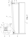
- FIG. 7 is a diagram showing a third process of mounting the fitting member to the first panel and the second panel according to the embodiment of the present invention.
- FIG. 8 is a diagram showing the fitting member being completely mounted to the first panel and the second panel according to the embodiment of the present invention.
- FIG. 9 is a partial view of the fitting member not being completely mounted to the second panel according to the embodiment of the present invention.
- FIG. 10 is a partial view of the fitting member being completely mounted to the second panel according to the embodiment of the present invention.
- a furniture system 20 includes a first side wall 22 , a second side wall 24 , a bottom plate 26 , a first panel 28 and a second panel 30 according to an embodiment of the present invention.
- the furniture system 20 is a drawer, but the present invention is not limited thereto.
- the first side wall 22 and the second side wall 24 are arranged at a left side and a right side of the bottom plate 26 respectively.
- the left and right sides are only for illustration to facilitate understanding of relative positions, that is, the left and right sides are interchangeable, and are not intended to limit the specific positions.
- the first panel 28 and the second panel 30 are arranged at a front side and a rear side of the bottom plate 26 respectively.
- the first panel 28 is a front panel
- the second panel 30 is a rear panel (or back panel), but the present invention is not limited thereto.
- the first side wall 22 , the second side wall 24 , the bottom plate 26 , the first panel 28 and the second panel 30 together define an accommodating space for accommodating objects.
- the X-axis is a length direction of the furniture system 20
- the Y-axis is a width direction of the furniture system 20
- the Z-axis is a height direction of the furniture system 20 .
- the length direction, the width direction and the height direction are perpendicular to each other.
- left and right sides of the furniture system 20 have substantially identical structural arrangement.
- the left side and the right side of the furniture system 20 can be respectively arranged with a first fitting member 32 and a second fitting member 34 to increase heights of the left and right sides of the furniture system 20 , so as to match heights of the first panel 28 and the second panel 30 .
- the first fitting member 32 is illustrated since the second fitting member 34 is similar to the first fitting member 32 .
- the first fitting member 32 can be a rod or a wall.
- the first fitting member 32 is a rod, but the present invention is not limited thereto.
- a length of the rod is substantially identical to a length of the first side wall 22 .
- the first panel 28 and the first fitting member 32 together form a furniture assembly.
- the furniture assembly further comprises the second panel 30 .
- the first fitting member 32 is configured to be detachably connected to the first panel 28 and the second panel 30 .
- the first panel 28 is arranged with a first connecting feature 40
- the fitting member 32 comprises a first part 36 and a second part 38 , such as a front part and a rear part, located at opposite positions, but the present invention is not limited thereto.
- the first fitting member 32 is arranged with a second connecting feature 42 configured to be detachably connected with the first connecting feature 40 of the first panel 28 .
- the second connecting feature 42 is located adjacent to the first part 36 of the first fitting member 32 .
- the second panel 30 is arranged with a first engaging structure 44
- the first fitting member 32 is further arranged with a second engaging structure 46 (please also refer to FIG. 4 ) located adjacent to the second part 38 of the first fitting member 32 .
- the second engaging structure 46 is configured to be detachably connected with the first engaging structure 44 .
- one of the first engaging structure 44 and the second engaging structure 46 is a protrusion.
- the first engaging structure 44 is a protrusion
- the protrusion defines a mounting space S (as shown in FIG. 3 ).
- the other one of the first engaging structure 44 and the second engaging structure 46 is an extension piece.
- the second engaging structure 46 is an extension piece (please also refer to FIG. 4 ), and the extension piece is configured to be mounted (for example, inserted) into the mounting space S, such that the extension piece and the protrusion support or abut against each other.
- one of the first connecting feature 40 and the second connecting feature 42 is formed with a space 48 , and the space 48 is arranged with a guiding section 50 and an engaging section 52 adjacent to the guiding section 50 therein.
- the guiding section 50 has an inclined surface or an arc surface (as shown in FIG. 4 ).
- the second panel 30 further comprises a first mounting feature 54 (as shown in FIG. 3 ), and the first fitting member 32 is further arranged with a second mounting feature 56 (as shown in FIG. 4 ) configured to be detachably connected with the first mounting feature 54 .
- the first fitting member 32 is further arranged with an auxiliary member 58 adjacent to the second part 38 .
- the auxiliary member 58 comprises a first auxiliary part 60 and a second auxiliary part 62 bent relative to the first auxiliary part 60 .
- the first auxiliary part 60 and the second auxiliary part 62 are substantially perpendicularly connected to each other, but the present invention is not limited thereto.
- the second engaging structure 46 is arranged on the first auxiliary part 60 of the auxiliary member 58
- the second mounting feature 56 is arranged on the second auxiliary part 62 of the auxiliary member 58 (as shown in FIG. 4 ).
- the first side wall 22 is connected between the first panel 28 and the second panel 30 .
- the other one of the first connecting feature 40 and the second connecting feature 42 comprises a head part 64 and an extension part 66 .
- the first connecting feature 40 comprises the head part 64 and the extension part 66 .
- the extension part 66 is connected between the head part 64 and the first panel 28 .
- the second connecting feature 42 has the space 48 , the guiding section 50 and the engaging section 52 .
- the space 48 is configured to allow the head part 64 (and the extension part 66 ) of the first connecting feature 40 to enter therein (as shown in FIG. 5 ), and the guiding section 50 is configured to guide the head part 64 (as shown in FIG. 6 ) of the first connecting feature 40 to be engaged with the engaging section 52 (as shown in FIG. 7 ), such that the first fitting member 32 is detachably connected to the first panel 28 .
- a user can press the second part 38 (such as the rear part) of the first fitting member 32 along a first predetermined direction D 1 (such as a top-down direction shown in FIG. 7 and FIG. 8 ), in order to mount the second engaging structure 46 of the first fitting member 32 to the first engaging structure 44 of the second panel 30 .
- the first mounting feature 54 of the second panel 30 is a predetermined wall having a predetermined shape or outline
- the second mounting feature 56 of the first fitting member 32 is an elastic element (or elastic arm).
- the first mounting feature 54 can be an elastic element (or elastic arm)
- the second mounting feature 56 can be a predetermined wall, but the present invention is not limited thereto.
- the second mounting feature 56 contacts a wall surface 70 of the second panel 30 to accumulate an elastic force F (as shown in FIG. 9 ).
- the first fitting member 32 is located at a mounting position (as shown in FIG. 10 )
- the second mounting feature 56 releases the elastic force F, such that the second mounting feature 56 is blocked by the first mounting feature 54 to prevent the first fitting member 32 from being detached from the second panel 30 along a second predetermined direction D 2 opposite to the first predetermined direction D 1 .
- the first fitting member 32 is mounted to the second panel 30 (as shown in FIG. 10 ).
- the first fitting member 32 further comprises an operating part 68 connected to the second mounting feature 56 .
- the user can apply an operating force K to the operating part 68 in a direction opposite to a direction of the elastic force F (as shown in FIG. 10 ), in order to drive the second mounting feature 56 to move, such that the second mounting feature 56 is no longer blocked by the first mounting feature 56 , in order to allow the second part 38 (such as the rear part) of the first fitting member 32 to be lifted along the second predetermined direction D 2 and detached from the second panel 30 (as shown in FIG. 9 ). As such, the first fitting member 32 can be detached from the second panel 30 .
- the second connecting feature 42 of the first part 36 (such as the front part) of the first fitting member 32 can be detached from the first connecting feature 40 of the first panel 28 .
- the head part 64 of the first connecting feature 40 is detach from the engaging section 52 of the second connecting feature 42 , such that the first fitting member 32 can be detached from the first panel 28 (please also refer to FIG. 5 ).
- the furniture system and the furniture assembly according to the embodiments of the present invention has the following technical features:
Landscapes
- Connection Of Plates (AREA)
- Drawers Of Furniture (AREA)
- Assembled Shelves (AREA)
- Furniture Connections (AREA)
- Combinations Of Kitchen Furniture (AREA)
Abstract
Description
-
- 1. The first
fitting member 32 and thefirst panel 28 are detachably connected to each other through the first connecting feature 40 and the second connectingfeature 42. One of the first connecting feature 40 and the second connectingfeature 42 is formed with aspace 48, and a guiding section and an engagingsection 52 are arranged in thespace 48. Therefore, after entering thespace 48, thehead part 64 of the other one of the first connecting feature 40 and the second connectingfeature 42 can be guided by the guidingsection 50 to be engaged with the engagingsection 52. Compared with the prior art that requires a spring or an actuator, the detachable connection design between the firstfitting member 32 and thefirst panel 28 has simpler structural configuration, and can meet diverse requirements of the market. - 2. When the user is going to detach the first
fitting member 32 from thefirst panel 28 and thesecond panel 30, the user can first detach the firstfitting member 32 from thesecond panel 30, and then further detach the firstfitting member 32 from thefirst panel 28. Such configuration is convenient for the user. For example, after detaching the firstfitting member 32 from thesecond panel 30, thehead part 64 of the first connecting feature 40 is allowed to be detached from the engagingsection 52 of the second connectingfeature 42 accordingly, such that the firstfitting member 32 can be detached from thefirst panel 28.
- 1. The first
Claims (8)
Applications Claiming Priority (2)
| Application Number | Priority Date | Filing Date | Title |
|---|---|---|---|
| TW112108390 | 2023-03-06 | ||
| TW112108390A TWI838155B (en) | 2023-03-06 | 2023-03-06 | Furniture and furniture assembly thereof |
Publications (2)
| Publication Number | Publication Date |
|---|---|
| US20240298795A1 US20240298795A1 (en) | 2024-09-12 |
| US12329279B2 true US12329279B2 (en) | 2025-06-17 |
Family
ID=88097381
Family Applications (1)
| Application Number | Title | Priority Date | Filing Date |
|---|---|---|---|
| US18/347,045 Active 2043-12-06 US12329279B2 (en) | 2023-03-06 | 2023-07-05 | Furniture system and furniture assembly thereof |
Country Status (4)
| Country | Link |
|---|---|
| US (1) | US12329279B2 (en) |
| EP (1) | EP4427634B1 (en) |
| JP (1) | JP7687573B2 (en) |
| TW (1) | TWI838155B (en) |
Citations (11)
| Publication number | Priority date | Publication date | Assignee | Title |
|---|---|---|---|---|
| US5076652A (en) | 1989-10-18 | 1991-12-31 | Karl Lautenschlager Gmbh & Co. Kg | Drawer railing |
| US20110163647A1 (en) * | 2008-09-18 | 2011-07-07 | Hartl Fabian | Movable drawer with railing adjustment |
| US20130293079A1 (en) * | 2011-01-03 | 2013-11-07 | Julius Blum Gmbh | Rail for a movable furniture part |
| WO2013185154A2 (en) * | 2012-06-12 | 2013-12-19 | Julius Blum Gmbh | Drawer railing |
| US20180177297A1 (en) * | 2015-07-01 | 2018-06-28 | Form Orange Produktentwicklung | Drawer comprising a base panel, a screen, a rear wall and two lateral walls which are rigidly interconnected |
| US20200315347A1 (en) * | 2017-12-21 | 2020-10-08 | Julius Blum Gmbh | Rail bar for a drawer |
| US11122895B2 (en) | 2017-12-21 | 2021-09-21 | Julius Blum Gmbh | Railing strut for a drawer |
| US20240000231A1 (en) * | 2022-07-04 | 2024-01-04 | King Slide Works Co., Ltd. | Furniture and furniture part assembly thereof |
| US20240000230A1 (en) * | 2022-07-04 | 2024-01-04 | King Slide Works Co., Ltd. | Furniture and furniture part assembly thereof |
| US20240003370A1 (en) * | 2022-07-04 | 2024-01-04 | King Slide Works Co., Ltd. | Furniture and furniture part assembly thereof |
| US20240301904A1 (en) * | 2023-03-06 | 2024-09-12 | King Slide Works Co., Ltd. | Furniture System and Furniture Assembly Thereof |
Family Cites Families (5)
| Publication number | Priority date | Publication date | Assignee | Title |
|---|---|---|---|---|
| AT402596B (en) * | 1994-08-26 | 1997-06-25 | Blum Gmbh Julius | FURNITURE FITTING, IN PARTICULAR FITTING FITTING FURNITURE FITTING, PARTICULAR FITTING FITTING |
| DE29507834U1 (en) * | 1995-05-17 | 1995-07-13 | Mepla-Werke Lautenschläger GmbH & Co KG, 64354 Reinheim | Rail fastening arrangement on drawers |
| AT518790B1 (en) * | 2017-02-21 | 2018-01-15 | Blum Gmbh Julius | Connecting pin for furniture parts |
| AT520913A1 (en) * | 2018-02-01 | 2019-08-15 | Blum Gmbh Julius | furniture accessories |
| TWM616617U (en) * | 2021-06-10 | 2021-09-01 | 黃松平 | Detachable furniture panel structure combination |
-
2023
- 2023-03-06 TW TW112108390A patent/TWI838155B/en active
- 2023-07-05 US US18/347,045 patent/US12329279B2/en active Active
- 2023-09-20 EP EP23198482.4A patent/EP4427634B1/en active Active
- 2023-10-13 JP JP2023177176A patent/JP7687573B2/en active Active
Patent Citations (13)
| Publication number | Priority date | Publication date | Assignee | Title |
|---|---|---|---|---|
| US5076652A (en) | 1989-10-18 | 1991-12-31 | Karl Lautenschlager Gmbh & Co. Kg | Drawer railing |
| US20110163647A1 (en) * | 2008-09-18 | 2011-07-07 | Hartl Fabian | Movable drawer with railing adjustment |
| US20130293079A1 (en) * | 2011-01-03 | 2013-11-07 | Julius Blum Gmbh | Rail for a movable furniture part |
| US9161624B2 (en) | 2011-01-03 | 2015-10-20 | Julius Blum Gmbh | Rail for a movable furniture part |
| WO2013185154A2 (en) * | 2012-06-12 | 2013-12-19 | Julius Blum Gmbh | Drawer railing |
| US20180177297A1 (en) * | 2015-07-01 | 2018-06-28 | Form Orange Produktentwicklung | Drawer comprising a base panel, a screen, a rear wall and two lateral walls which are rigidly interconnected |
| US20200315347A1 (en) * | 2017-12-21 | 2020-10-08 | Julius Blum Gmbh | Rail bar for a drawer |
| US11122895B2 (en) | 2017-12-21 | 2021-09-21 | Julius Blum Gmbh | Railing strut for a drawer |
| US11219312B2 (en) | 2017-12-21 | 2022-01-11 | Julius Blum Gmbh | Rail bar for a drawer |
| US20240000231A1 (en) * | 2022-07-04 | 2024-01-04 | King Slide Works Co., Ltd. | Furniture and furniture part assembly thereof |
| US20240000230A1 (en) * | 2022-07-04 | 2024-01-04 | King Slide Works Co., Ltd. | Furniture and furniture part assembly thereof |
| US20240003370A1 (en) * | 2022-07-04 | 2024-01-04 | King Slide Works Co., Ltd. | Furniture and furniture part assembly thereof |
| US20240301904A1 (en) * | 2023-03-06 | 2024-09-12 | King Slide Works Co., Ltd. | Furniture System and Furniture Assembly Thereof |
Also Published As
| Publication number | Publication date |
|---|---|
| US20240298795A1 (en) | 2024-09-12 |
| EP4427634A1 (en) | 2024-09-11 |
| TW202435797A (en) | 2024-09-16 |
| JP7687573B2 (en) | 2025-06-03 |
| EP4427634B1 (en) | 2025-11-05 |
| JP2024125987A (en) | 2024-09-19 |
| TWI838155B (en) | 2024-04-01 |
Similar Documents
| Publication | Publication Date | Title |
|---|---|---|
| US10278498B2 (en) | Bracket device and slide rail assembly comprising the same | |
| US10213017B2 (en) | Slide rail assembly | |
| US10194556B2 (en) | Slide rail mechanism and bracket device thereof | |
| TW202211838A (en) | Slide rail kit | |
| TWI548369B (en) | Mounting part for slide rail assembly | |
| TWI712382B (en) | Connection device | |
| US10772422B1 (en) | Connecting device | |
| US12329279B2 (en) | Furniture system and furniture assembly thereof | |
| US4387484A (en) | Supporting bracket for side handles of utensils | |
| US20240301904A1 (en) | Furniture System and Furniture Assembly Thereof | |
| US4668036A (en) | Large picture display device | |
| US11992121B2 (en) | Fixing assembly | |
| TWI806690B (en) | Furniture and furniture assembly thereof | |
| US12440026B2 (en) | Slide rail kit | |
| US12022944B2 (en) | Furniture and furniture part assembly thereof | |
| CN118614719A (en) | Furniture and furniture components | |
| JP7321525B2 (en) | slide rail unit | |
| US20250311847A1 (en) | Slide rail assembly | |
| CN223806449U (en) | Detachable hook and hook assembly | |
| JP4431165B2 (en) | connector | |
| JP2778934B2 (en) | Shelf support | |
| CN117432692A (en) | Furniture and furniture assembly thereof | |
| JPH09254049A (en) | Part removing tool | |
| CN118452649A (en) | Drawer with drawer panel easy to disassemble and assemble and cabinet | |
| CN116798815A (en) | Clamp spring structure of relay and relay module |
Legal Events
| Date | Code | Title | Description |
|---|---|---|---|
| AS | Assignment |
Owner name: KING SLIDE TECHNOLOGY CO., LTD., TAIWAN Free format text: ASSIGNMENT OF ASSIGNORS INTEREST;ASSIGNORS:CHEN, KEN-CHING;SU, FANG-CHENG;TANG, YUE-HUA;AND OTHERS;REEL/FRAME:064153/0099 Effective date: 20230630 Owner name: KING SLIDE WORKS CO., LTD., TAIWAN Free format text: ASSIGNMENT OF ASSIGNORS INTEREST;ASSIGNORS:CHEN, KEN-CHING;SU, FANG-CHENG;TANG, YUE-HUA;AND OTHERS;REEL/FRAME:064153/0099 Effective date: 20230630 |
|
| FEPP | Fee payment procedure |
Free format text: ENTITY STATUS SET TO UNDISCOUNTED (ORIGINAL EVENT CODE: BIG.); ENTITY STATUS OF PATENT OWNER: LARGE ENTITY |
|
| STPP | Information on status: patent application and granting procedure in general |
Free format text: DOCKETED NEW CASE - READY FOR EXAMINATION |
|
| STPP | Information on status: patent application and granting procedure in general |
Free format text: NON FINAL ACTION MAILED |
|
| STCF | Information on status: patent grant |
Free format text: PATENTED CASE |