US12327473B2 - Vehicle monitoring system, vehicle monitoring method, and vehicle monitoring apparatus - Google Patents
Vehicle monitoring system, vehicle monitoring method, and vehicle monitoring apparatus Download PDFInfo
- Publication number
- US12327473B2 US12327473B2 US17/795,942 US202017795942A US12327473B2 US 12327473 B2 US12327473 B2 US 12327473B2 US 202017795942 A US202017795942 A US 202017795942A US 12327473 B2 US12327473 B2 US 12327473B2
- Authority
- US
- United States
- Prior art keywords
- vehicle
- monitored
- sound information
- optical fiber
- road
- Prior art date
- Legal status (The legal status is an assumption and is not a legal conclusion. Google has not performed a legal analysis and makes no representation as to the accuracy of the status listed.)
- Active, expires
Links
Images


Classifications
-
- G—PHYSICS
- G08—SIGNALLING
- G08G—TRAFFIC CONTROL SYSTEMS
- G08G1/00—Traffic control systems for road vehicles
- G08G1/01—Detecting movement of traffic to be counted or controlled
- G08G1/017—Detecting movement of traffic to be counted or controlled identifying vehicles
- G08G1/0175—Detecting movement of traffic to be counted or controlled identifying vehicles by photographing vehicles, e.g. when violating traffic rules
-
- G—PHYSICS
- G08—SIGNALLING
- G08G—TRAFFIC CONTROL SYSTEMS
- G08G1/00—Traffic control systems for road vehicles
- G08G1/01—Detecting movement of traffic to be counted or controlled
- G08G1/017—Detecting movement of traffic to be counted or controlled identifying vehicles
-
- G—PHYSICS
- G08—SIGNALLING
- G08G—TRAFFIC CONTROL SYSTEMS
- G08G1/00—Traffic control systems for road vehicles
- G08G1/01—Detecting movement of traffic to be counted or controlled
- G08G1/02—Detecting movement of traffic to be counted or controlled using treadles built into the road
-
- G—PHYSICS
- G08—SIGNALLING
- G08G—TRAFFIC CONTROL SYSTEMS
- G08G1/00—Traffic control systems for road vehicles
- G08G1/01—Detecting movement of traffic to be counted or controlled
- G08G1/04—Detecting movement of traffic to be counted or controlled using optical or ultrasonic detectors
Definitions
- the present disclosure relates to a vehicle monitoring system, a vehicle monitoring method, and a vehicle monitoring apparatus.
- Patent Literature 1 systems for monitoring vehicles (automobiles) traveling on roads using optical fibers.
- Patent Literature 1 Published Japanese Translation of PCT International Publication for Patent Application, No. 2009-514081
- Patent Literature 1 when the aforementioned frequency deviation is occurring in the specified section of the optical fibers, it can be detected that there is a moving vehicle present in the specified section. However, when attempting to monitor a specific vehicle-to-be-monitored traveling on the road, it cannot be determined whether the vehicle that is detected in the specified section is the vehicle-to-be-monitored, which leads to a problem that it is difficult to perform monitoring of a vehicle-to-be-monitored.
- an object of the present disclosure is to provide a vehicle monitoring system, a vehicle monitoring method, and a vehicle monitoring apparatus each adapted to solve the aforementioned problem and to monitor a vehicle-to-be-monitored with high accuracy.
- An aspect of the present disclosure is a vehicle monitoring system including:
- An aspect of the present disclosure is a vehicle monitoring method performed by a vehicle monitoring system, including:
- An aspect of the present disclosure is a vehicle monitoring apparatus including:
- an effect of providing a vehicle monitoring system, a vehicle monitoring method, and a vehicle monitoring apparatus each adapted to monitor a vehicle-to-be-monitored with high accuracy can be obtained.
- FIG. 1 is a diagram showing a configuration example of a vehicle monitoring system according to a first example embodiment
- FIG. 2 is a diagram showing an example of the contents of a correspondence table held by an identification unit according to the first example embodiment
- FIG. 3 is a flowchart showing an example of overall operation flow of the vehicle monitoring system according to the first example embodiment
- FIG. 4 is a diagram showing a configuration example of a vehicle monitoring system according to a second example embodiment
- FIG. 5 is a diagram showing an example of the contents of a correspondence table held by an acquisition unit according to the second example embodiment
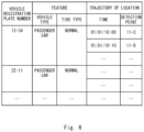
- FIG. 6 is a diagram showing an example of the contents of a vehicle DB according to the second example embodiment
- FIG. 7 is a diagram showing an example of data that is obtainable by a retrieval unit according to the second example embodiment
- FIG. 8 is a flowchart showing an example of operation flow of registering information about a vehicle that has passed a predetermined location on the road in a vehicle DB in the vehicle monitoring system according to the second example embodiment;
- FIG. 9 is a flowchart showing an example of operation flow of retrieving information about a vehicle-to-be-monitored from the vehicle DB in the vehicle monitoring system according to the second example embodiment.
- FIG. 10 is a block diagram showing a hardware configuration of a computer that realizes the vehicle monitoring apparatuses according to the example embodiments.
- the vehicle monitoring system includes an optical fiber for sensing 10 , a vehicle monitoring apparatus 20 , and a vehicle passage detecting unit 30 . Further, the vehicle monitoring apparatus 20 includes a reception unit 201 and an identification unit 202 .
- the optical fiber for sensing 10 is laid along a road 40 .
- the optical fiber for sensing 10 is intended to be laid on the side of the road 40 but the method of laying the optical fiber for sensing 10 is not limited thereto.
- the optical fiber for sensing 10 may be buried under the road 40 .
- the road 40 may be any road such as an expressway or a local road as long as the optical fiber for sensing 10 is laid.
- the optical fiber for sensing 10 may be laid on the road 40 in a form of a cable configured by coating one or more optical fibers for sensing 10 .
- the optical fiber for sensing 10 may be an existing optical fiber for communication or may be a newly laid optical fiber.
- the vehicle passage detecting unit 30 is configured to detect that a vehicle 50 has passed a predetermined location on the road 40 .
- the vehicle passage detecting unit 30 is intended to be a vehicle registration plate number reading apparatus used in N (Number)-systems or the like installed at a predetermined location on the road 40 .
- the vehicle registration plate number reading apparatus captures an image of a vehicle 50 before it passes thereby with a camera and reads the vehicle registration plate number of the vehicle 50 that has passed thereby from the camera image.
- the vehicle passage detecting unit 30 is not limited to a vehicle registration plate number reading apparatus.
- the vehicle passage detecting unit 30 may be an ETC (Electronic Toll Collection) gate installed at a predetermined location on the road 40 .
- the ETC gate performs communication with an ETC on-board device installed on the vehicle 50 that has passed through the ETC gate and obtains information recorded on the ETC card inserted in the ETC on-board device.
- the identification unit 202 identifies the vehicle 50 that is detected by the vehicle passage detecting unit 30 as having passed the predetermined location on the road 40 as the vehicle-to-be-monitored.
- the reception unit 201 receives the reflected lights and the scattered lights that are generated when the pulsed lights are made incident on the optical fiber for sensing 10 and the incident pulsed lights are transmitted through the optical fiber for sensing 10 as return lights (optical signals) through the optical fiber for sensing 10 .
- the optical fiber for sensing 10 can detect sound information indicating sounds generated due to traveling of the vehicle 50 on the road 40 . Further, since the characteristics of the return lights that are transmitted through the optical fiber for sensing 10 change in accordance with the sound information detected by the optical fiber for sensing 10 , the return lights include the sound information detected by the optical fiber for sensing 10 .
- the sound information generated due to traveling of the vehicle 50 on the road 40 is a dynamically varying sound pattern and indicates a unique sound pattern with different sound intensity, sound fluctuation transition, and so forth depending on the vehicle 50 that traveled on the road 40 .
- the sound information detected at any given detection point 11 in the optical fiber for sensing 10 is shown under the pertinent detection point 11 .
- the sound information shown in FIG. 1 indicates time on the horizontal axis and sound intensity on the vertical axis, and shows a sound pattern corresponding to the vehicle 50 that is traveling on the road 40 .
- the return lights received by the reception unit 201 include the sound information unique to the vehicle 50 that traveled on the road 40 .
- the return lights also include the sound information unique to the vehicle-to-be-monitored identified by the identification unit 202 . Therefore, the identification unit 202 is able to identify the vehicle-to-be-monitored based on the sound information unique to the vehicle-to-be-monitored included in the return lights.
- the identification unit 202 can identify, based on, for example, the time difference between when the reception unit 201 transmits the pulsed lights to the optical fiber for sensing 10 and when the reception unit 201 receives the return lights, and the intensity and the like of the return lights received by the reception unit 201 , at which locations (the distance from the vehicle monitoring apparatus 20 ) in the optical fiber for sensing 10 the received return lights were generated.
- the identification unit 202 holds, in advance, a correspondence table for each vehicle passage detecting unit 30 , the correspondence table being a table in which an identification number for identifying the vehicle passage detecting unit 30 , the detection point 11 corresponding to the predetermined location at which passage of the vehicle 50 is detected by the vehicle passage detecting unit 30 , and the location information indicating the location (the distance from the vehicle monitoring apparatus 20 ) of the pertinent detection point 11 are in correspondence relationship with one another.
- An example of the contents of the correspondence table is shown in FIG. 2 . Note that in FIG. 2 , it is assumed that there are a plurality of vehicle passage detecting units 30 present along the road 40 , but at least one vehicle passage detecting unit 30 may be present along the road 40 .
- the identification unit 202 can obtain the sound information detected by the optical fiber for sensing 10 at the detection point 11 corresponding to the predetermined location on the road 40 . Therefore, the sound information of the vehicle 50 detected by the optical fiber for sensing 10 at the detection point 11 corresponding to the predetermined location may be obtained when the vehicle passage detecting unit 30 detects that the vehicle-to-be-monitored has passed the predetermined location on the road 40 , and the obtained sound information may be identified as the sound information unique to the vehicle-to-be-monitored.
- the identification unit 202 can identify at which locations in the optical fiber for sensing 10 the return lights received by the reception unit 201 were generated.
- the identification unit 202 is able to identify the location of the vehicle-to-be-monitored by identifying at which locations in the optical fiber for sensing 10 the return lights including the sound information unique to the vehicle-to-be-monitored were generated.
- the sound information generated due to traveling of the vehicle 50 on the road 40 indicates a unique sound pattern corresponding to the pertinent traveling vehicle 50 .
- this sound pattern is considered to differ depending on the features of the vehicle 50 .
- the features of the vehicle 50 are, for example, the vehicle type (e.g. a general passenger car, a bus, a truck, etc.), the tire type (e.g. normal tires, studless tires, tires with chains, etc.), and so on.
- the identification unit 202 is able to identify the features of the vehicle-to-be-monitored by analyzing the dynamic variation in the sound pattern indicated by the sound information unique to the vehicle-to-be-monitored.
- a method of identifying the features of the vehicle-to-be-monitored in the identification unit 202 may be a method utilizing pattern matching.
- the identification unit 202 holds, in advance for each vehicle type, the sound pattern corresponding to the vehicle type as the matching pattern.
- the identification unit 202 compares the sound pattern indicated by the sound information of the vehicle-to-be-monitored with the matching pattern for each vehicle type.
- the identification unit 202 determines that the vehicle type of the vehicle-to-be-monitored is the vehicle type corresponding to that matching pattern.
- the identification unit 202 may hold the matching pattern for each tire type in advance and determine the tire type of the vehicle-to-be-monitored by the same method as that for determining the vehicle type.
- a method of identifying the features of the vehicle-to-be-monitored in the identification unit 202 may be a method utilizing a training model of a Convolutional Neural Network (CNN).
- CNN Convolutional Neural Network
- the identification unit 202 inputs a plurality of pairs of the training data indicating the vehicle types and the sound patterns corresponding to the vehicle types, and pre-builds and holds a learning model for each vehicle type.
- the identification unit 202 inputs the sound pattern indicating the sound information of the vehicle-to-be-monitored in the learning model. Accordingly, the identification unit 202 obtains the vehicle type of the vehicle-to-be-monitored as a result of output of the learning model.
- the identification unit 202 may build and hold a learning model in advance and determine the tire type of the vehicle-to-be-monitored by the same method as that for determining the vehicle type.
- the sound pattern used for identifying the vehicle-to-be-monitored is not limited to the sound patterns of the sound information like those shown in FIG. 1 .
- the sound pattern used for identifying the vehicle-to-be-monitored may be a sound pattern of sound information obtained by performing frequency analysis of the sound information shown in FIG. 1 or may be a sound pattern of sound information obtained by performing further filtering of the aforementioned frequency-analyzed sound information.
- the identification unit 202 can identify the location of the vehicle-to-be-monitored based on the sound information unique to the vehicle-to-be-monitored detected by the optical fiber for sensing 10 at the arbitrary detection point 11 .
- the identification unit 202 may identify the trajectory of the location of the vehicle-to-be-monitored based on the sound information unique to the vehicle-to-be-monitored detected by the optical fiber for sensing 10 at a plurality of detection points 11 (two detection points 11 in FIG. 1 ) and track the vehicle-to-be-monitored based on the identified trajectory of the location of the vehicle-to-be-monitored.
- a vehicle registration plate number reading apparatus can be employed for the vehicle passage detecting unit 30 .
- the vehicle passage detecting unit 30 that is a vehicle registration plate number reading apparatus can not only detect passage of the vehicle 50 but can also read the vehicle registration plate number of the vehicle 50 that has passed thereby.
- the identification unit 202 may hold the features and the location of the vehicle-to-be-monitored in correspondence relationship with the vehicle registration plate of the vehicle-to-be monitored.
- the identification unit 202 identifies the vehicle-to-be-monitored based on the sound information unique to the vehicle-to-be-monitored included in the return lights received by the reception unit 201 (Step S 103 ).
- monitoring of the vehicle-to-be-monitored can be performed using N-systems that read the vehicle registration plate numbers of the plurality of vehicles 50 from the camera images.
- the range that is monitorable by each N-system is limited to the range within which a camera is installed, and the vehicle-to-be-monitored cannot be monitored outside this range.
- monitoring of the vehicle-to-be monitored can also be performed by installing a positioning apparatus utilizing GPS (Global Positioning System) and the like on the vehicle-to-be-monitored and acquiring location information measured by the vehicle-to-be-monitored.
- GPS Global Positioning System
- monitoring of the vehicles-to-be-monitored can be performed as long as there are optical fibers for sensing 10 , it is possible to monitor the vehicle-to-be-monitored over a wide range where the optical fibers for sensing 10 are laid.
- an existing optical fiber for communication may be employed for the optical fiber for sensing 10 .
- an existing optical fiber for communication since there is no need to prepare any additional equipment for performing monitoring of the vehicle-to-be-monitored, it is possible to configure a vehicle monitoring system at a low cost.
- an optical fiber sensing technique is utilized in which the optical fiber for sensing 10 is employed as the sensor. Accordingly, it is possible to gain advantages such as being free of the influence of the electromagnetic noise, eliminating the need to feed power to the sensors, excellent environmental tolerance, and easier maintenance.
- a vehicle monitoring system according to a second example embodiment is a more specific version of the aforementioned vehicle monitoring system according to the first example embodiment.
- the vehicle monitoring system according to the second example embodiment is configured by replacing the vehicle monitoring apparatus 20 according to the first example embodiment with a vehicle monitoring system 20 A and replacing the vehicle passage detecting unit 30 with a vehicle registration plate number reading apparatus 30 A.
- the vehicle monitoring apparatus 20 A includes a reception unit 211 , an acquisition unit 212 , a frequency analysis unit 213 , a filtering unit 214 , an extraction unit 215 , an integration unit 216 , a vehicle DB (Database) 217 , and a retrieval unit 218 .
- reception unit 211 corresponds to the reception unit 201 shown in FIG. 1 .
- the combination of the acquisition unit 212 , the frequency analysis unit 213 , the filtering unit 214 , the extraction unit 215 , the integration unit 216 , the vehicle DB 217 , and the retrieval unit 218 correspond to the identification unit 202 shown in FIG. 1 .
- the reception unit 211 receives the reflected lights and the scattered lights that were generated due to the pulsed lights being made incident on the optical fiber for sensing 10 and the incident pulsed lights being transmitted through the optical fiber for sensing 10 as return lights (optical signals) through the optical fiber for sensing 10 .
- the return lights received by the reception unit 211 include sound information indicating sounds generated by the vehicle 50 traveling on the road 40 .
- the acquisition unit 212 can identify, based on, for example the time difference between when the reception unit 211 transmits pulsed lights to the optical fiber for sensing 10 and when the reception unit 211 receives the return lights, and the light intensity and the like of the return lights received by the reception unit 211 , at which locations (the distance from the vehicle monitoring apparatus 20 A) in the optical fiber for sensing 10 the return lights were generated.
- the acquisition unit 212 holds, in advance a correspondence table for each detection point 11 of the plurality of detection points 11 in the optical fiber for sensing 10 , the correspondence table being a table in which an identification number for identifying each identification point 11 and the location information indicating the location (the distance from the vehicle monitoring apparatus 20 ) of each detection point 11 are in correspondence relationship with one another. Further, regarding the detection points 11 corresponding to the predetermined locations at which each vehicle registration plate number reading apparatus 30 A detects passage of the vehicle 50 , the identification number for identifying each vehicle registration plate number reading apparatus 30 A is held in correspondence relationship with the respective detection points 11 . An example of the contents of the correspondence table is shown in FIG. 5 .
- the acquisition unit 212 can identify at which detection point 11 the received return lights were generated by comparing the location in the optical fiber for sensing 10 at which the return lights were generated with the correspondence datable shown in FIG. 5 .
- the acquisition unit 212 acquires, for each of the plurality of detection points 11 , the sound information included in the return light based on the return lights generated at the respective detection points 11 .
- the frequency analysis unit 213 performs frequency analysis of the sound information acquired by the acquisition unit 212 for each of the plurality of detection points 11 .
- the frequency analysis method may be, but not limited thereto, a method of wavelet transformation of sound information.
- the filtering unit 214 performs filtering of the sound information that has been frequency-analyzed by the frequency analysis unit 213 for each of the plurality of detection points 11 in order to remove the noise components.
- the sound information at each detection point 11 of the plurality of detection points 11 that has been filtered by the filtering unit 214 includes the sound information such as an exhaust sound, road noise, and so forth of a vehicle 50 traveling on the road 40 .
- the sound information of the vehicle 50 indicates a unique sound pattern that varies dynamically depending on the features of the pertinent vehicle 50 (e.g. the vehicle type, the tire type, etc.).
- the extraction unit 215 extracts the features of the traveling vehicle 50 .
- a method of extracting the features of the vehicle 50 in the extraction unit 215 may be a method utilizing pattern matching, a method utilizing a learning model, and so forth like those described above.
- the method of extracting the features of the vehicle 50 is not limited thereto.
- the extraction unit 215 extracts the time at which the aforementioned sound information was detected and information about the detection point 11 as information indicating the trajectory of the location of the pertinent vehicle 50 .
- a vehicle registration plate number reading apparatus 31 A is installed at a predetermined location on the road 40 and is configured to detect that the vehicle 50 has passed the predetermined location on the road 40 and read the vehicle registration plate number of the detected vehicle 50 .
- the integration unit 216 obtains the vehicle registration plate number of the vehicle 50 that has passed the predetermined location on the road 40 from the vehicle registration plate number reading apparatus 31 A.
- the integration unit 216 identifies the sound information of the vehicle 50 detected by the optical fiber for sensing 10 at the detection point 11 corresponding to the predetermined location when the vehicle registration plate number reading apparatus 31 A detects that the vehicle 50 has passed the predetermined location on the road 40 as the sound information of the vehicle 50 that has passed the predetermined location.
- the retrieval unit 218 can identify the traveling direction, the traveling speed, and acceleration/deceleration of the vehicle-to-be-monitored based on the data shown in the bottom diagram of FIG. 7 .
- the integration unit 216 identifies the sound information of the vehicle 50 detected by the optical fiber for sensing 10 at the detection point 11 corresponding to the predetermined location when the vehicle registration plate number reading apparatus 31 A detects that the vehicle 50 has passed the predetermined location on the road 40 as the sound information of the vehicle 50 that has passed the predetermined location. Then, the integration unit 216 integrates the vehicle registration plate number information of the vehicle 50 obtained from the vehicle registration plate number reading apparatus 31 A and the information about the features and the trajectory of the location of the vehicle 50 extracted from the sound information identified above by the extraction unit 215 as information about the same vehicle 50 (Step S 207 ).
- the retrieval unit 218 retrieves information about the vehicle-to-be-monitored from the vehicle DB 217 using the vehicle registration plate number of the vehicle-to be monitored as a key (Step S 303 ).
- the retrieval unit 218 can specify the features, the location, and the trajectory of the location of the vehicle-to-be-monitored from the vehicle DB 217 .
- the retrieval unit 218 is capable of tracking the vehicle-to-be-monitored based on the trajectory of the location of vehicle-to-be-monitored.
- the retrieval unit 218 can identify the traveling direction, the traveling speed, and acceleration/deceleration of the vehicle-to-be-monitored based on the trajectory of location of the vehicle-to-be-monitored.
- the computer 60 includes a processor 601 , a memory 602 , a storage 603 , an input/output interface (input and output I/F) 604 , a communication interface (communication I/F) 605 , and so forth.
- the processor 601 , the memory 602 , the storage 603 , the input/output interface 604 , and the communication interface 605 are connected with one another via a data transmission line for transmitting and receiving data with one another.
- the processor 601 is a processing unit such as a CPU (Central Processing Unit), a GPU (Graphics Processing Unit), or the like.
- the memory 602 is a memory such as a RAM (Random Access Memory), a ROM (Read Only Memory), or the like.
- the storage 603 may be a storage apparatus such a HDD (Hard Disk Drive), a SSD (Solid State Drive), a memory card, or the like. Further, the storage 603 may be a memory such as a RAM, a ROM, or the like.
- the storage 603 stores programs for implementing the functions of the structural elements of the vehicle monitoring apparatuses 20 and 20 A.
- the processor 601 implements the functions of the structural elements of the vehicle monitoring apparatuses 20 and 20 A by executing these programs.
- the processor 601 may read out these programs onto the memory 602 before executing them, or may execute the programs without reading them out onto the memory 602 .
- the memory 602 and the storage 603 also serve to store information and data held by the structural elements of the vehicle monitoring apparatuses 20 and 20 A.
- Non-transitory computer readable media include any type of tangible storage media.
- Examples of non-transitory computer readable media include magnetic storage media (such as floppy disks, magnetic tapes, hard disk drives, etc.), optical magnetic storage media (e.g. magneto-optical disks), CD-ROM (Compact Disc-ROM), CD-R (Compact Disc-Recordable), CD-R/W (CD-ReWritable), and semiconductor memories (such as mask ROM, PROM (Programmable ROM), EPROM (Erasable PROM), flash ROM, and RAM).
- magnetic storage media such as floppy disks, magnetic tapes, hard disk drives, etc.
- optical magnetic storage media e.g. magneto-optical disks
- CD-ROM Compact Disc-ROM
- CD-R Compact Disc-Recordable
- CD-R/W CD-ReWritable
- semiconductor memories such as mask ROM, PROM (Programmable ROM), EPROM (Erasable PROM), flash ROM, and
- the program may be provided to a computer using any type of transitory computer readable media.
- Examples of transitory computer readable media include electric signals, optical signals, and electromagnetic waves.
- Transitory computer readable media can provide the program to a computer via a wired communication line such as electric wires and optical fibers, or a wireless communication line.
- the input/output interface 604 is connected to a display device 6041 , an input device 6042 , a sound output device 6043 , and so forth.
- the display device 6041 is a device that displays a screen corresponding to graphics data processed by the processor 601 , such as a LCD (Liquid Crystal Display), a CRT (Cathode Ray Tube) display, or a monitor.
- the input device 6042 is a device that accepts operator's operation input, such as a keyboard, a mouse, or a touch sensor.
- the display device 6041 and the input device 6042 may be integrated and implemented as a touch panel.
- the sound output device 6043 is a device that performs acoustic output of sounds corresponding to acoustic data processed by the processor 601 , such as a speaker.
- the communication interface 605 transmits and receives data to and from external devices.
- the communication interface 605 performs communication with external devices via s wired communication line or a wireless communication line.
- the retrieval unit 218 can identify the traveling speed of the vehicle-to-be-monitored and acceleration/deceleration of the vehicle-to-be-monitored. Therefore, the retrieval unit 218 may identify the vehicles-to-be-monitored which are traveling at a speed exceeding the legal speed limit and the vehicles-to-be-monitored which are repeating acceleration and deceleration or are making heavy use of sudden braking as vehicles that are driven dangerously.
- the retrieval unit 218 may send an alert notification to a navigation apparatus mounted on the vehicle that is driven dangerously or on a vehicle 50 which is traveling nearby the vehicle that is driven dangerously, or a traffic information display apparatus installed on the road 40 .
- the method of sending an alert notification may be a method of displaying the contents of alert notification to the alerted destination or a method of audio outputting the contents of alert notification from the alerted destination.
- the optical fiber for sensing 10 detected sound information of the vehicle 50 that is traveling on the road 40 .
- the characteristics of the return lights transmitted through the optical fiber for sensing 10 change also when the temperature of the road 40 changes. Therefore, the optical fiber for sensing 10 can also detect temperature information of the road 40 and further, the return light transmitted through the optical fiber for sensing 10 also includes temperature information detected by the optical fiber for sensing 10 . Therefore, the acquisition unit 212 may acquire temperature information for each of the plurality of detection points 11 in the optical fiber for sensing 10 and identify the detection points 11 at which the road surface is frozen based on the temperature information for each of the plurality of detection points 11 . Note that identification of the detection points 11 at which the road surface is frozen may be performed by the acquisition unit 212 or may be performed by the other structural elements of the vehicle monitoring apparatus 20 A.
- the retrieval unit 218 can identify the features (e.g. the type of tire) of the vehicle-to-be-monitored and the trajectory of the location of the vehicle-to-be-monitored. Further, as described above, the retrieval unit 212 or other structural elements can identify the detection points 11 at which the road surface is frozen. Therefore, the retrieval unit 218 may identify that a vehicle-to-monitored with summer tires is approaching the detection point 11 at which the road surface is frozen.
- the features e.g. the type of tire
- the retrieval unit 212 or other structural elements can identify the detection points 11 at which the road surface is frozen. Therefore, the retrieval unit 218 may identify that a vehicle-to-monitored with summer tires is approaching the detection point 11 at which the road surface is frozen.
- the retrieval unit 218 may send an alert to the navigation apparatus mounted on the vehicle-to-be-monitored or to a traffic information display apparatus installed on the road 40 .
- the method of sending an alert is the same at that described above.
- the sound information of the vehicle 50 traveling on the road 40 is detected by the optical fiber for sensing 10 , but it is not limited thereto.
- a microphone may be installed at an arbitrary location on the road 40 and sound information of the vehicle 50 traveling on the road 40 may be collected with this microphone.
- a plurality of structural elements are provided to the vehicle monitoring apparatuses 20 and 20 A but it is not limited thereto.
- the plurality of structural elements provided to the vehicle monitoring apparatuses 20 and 20 A are not necessarily provided to one apparatus and may be distributed in a plurality of apparatuses.
- a vehicle monitoring system comprising:
- the identification unit identifies features and location of the vehicle-to-be-monitored based on the sound information unique to the vehicle-to-be-monitored.
- the identification unit identifies a trajectory of the location of the vehicle-to-be-monitored based on the sound information unique to the vehicle-to-be-monitored detected by the optical fiber for sensing at a plurality of detection points and tracks the vehicle-to-be-monitored based on the identified trajectory of the location of the vehicle-to-be-monitored.
- the identification unit identifies sound information of a vehicle detected by the optical fiber for sensing at a detection point corresponding to the predetermined location when the vehicle-to-be-monitored has passed the predetermined location as the sound information unique to the vehicle-to-be-monitored.
- vehicle passage detection unit is a vehicle registration plate number reading apparatus that reads a vehicle registration plate number of the vehicle that has passed the predetermined location.
- a vehicle monitoring apparatus comprising:
Landscapes
- Physics & Mathematics (AREA)
- General Physics & Mathematics (AREA)
- Traffic Control Systems (AREA)
Abstract
Description
-
- an optical fiber for sensing laid on a road;
- a vehicle passage detection unit configured to detect that a vehicle has passed a predetermined location on the road;
- an identification unit configured to identify the vehicle that has passed the predetermined location as a vehicle-to-be-monitored; and
- a reception unit configured to receive sound information unique to the vehicle-to-be-monitored detected by the optical fiber for sensing,
- in which the identification unit identifies the vehicle-to-be-monitored based on the sound information unique to the vehicle-to-be-monitored.
-
- a vehicle passage detection step of detecting that a vehicle has passed a predetermined location on a road;
- a first identification step of identifying the vehicle that has passed the predetermined location as a vehicle-to-be-monitored;
- a reception step of receiving sound information unique to the vehicle-to-be-monitored detected by an optical fiber for sensing laid on the road; and
- a second identification step of identifying the vehicle-to-be-monitored based on the sound information unique to the vehicle-to-be-monitored.
-
- an identification unit configured to identify a vehicle that has passed a predetermined location on a road as a vehicle-to-be-monitored; and
- a reception unit configured to receive sound information unique to the vehicle-to-be-monitored detected by an optical fiber for sensing laid on the road,
- in which the identification unit identifies the vehicle-to-be-monitored based on the sound information unique to the vehicle-to-be-monitored.
-
- an optical fiber for sensing laid on a road;
- a vehicle passage detection unit configured to detect that a vehicle has passed a predetermined location on the road;
- an identification unit configured to identify the vehicle that has passed the predetermined location as a vehicle-to-be-monitored; and
- a reception unit configured to receive sound information unique to the vehicle-to-be-monitored detected by the optical fiber for sensing,
- wherein the identification unit identifies the vehicle-to-be-monitored based on the sound information unique to the vehicle-to-be-monitored.
(Supplementary Note 2)
-
- a vehicle passage detection step of detecting that a vehicle has passed a predetermined location on a road;
- a first identification step of identifying the vehicle that has passed the predetermined location as a vehicle-to-be-monitored;
- a reception step of receiving sound information unique to the vehicle-to-be-monitored detected by an optical fiber for sensing laid on the road; and
- a second identification step of identifying the vehicle-to-be-monitored based on the sound information unique to the vehicle-to-be-monitored.
(Supplementary Note 8)
-
- an identification unit configured to identify a vehicle that has passed a predetermined location on a road as a vehicle-to-be-monitored; and
- a reception unit configured to receive sound information unique to the vehicle-to-be-monitored detected by an optical fiber for sensing laid on the road,
- wherein the identification unit identifies the vehicle-to-be-monitored based on the sound information unique to the vehicle-to-be-monitored.
-
- 10 OPTICAL FIBER FOR SENSING
- 20, 20A VEHICLE MONITORING APPARATUS
- 201 RECEPTION UNIT
- 202 IDENTIFICATION UNIT
- 211 RECEPTION UNIT
- 212 ACQUISITION UNIT
- 213 FREQUENCY ANALYSIS UNIT
- 214 FILTERING UNIT
- 215 EXTRACTION UNIT
- 216 INTEGRATION UNIT
- 217 VEHICLE DB
- 218 RETRIEVAL UNIT
- 30 VEHICLE PASSAGE DETECTION UNIT
- 30A VEHICLE REGISTRATION PLATE NUMBER READING APPARATUS
- 40 ROAD
- 50 VEHICLE
- 60 COMPUTER
- 601 PROCESSOR
- 602 MEMORY
- 603 STORAGE
- 604 INPUT/OUTPUT INTERFACE
- 6041 DISPLAY DEVICE
- 6042 INPUT DEVICE
- 6043 SOUND OUTPUT DEVICE
- 605 COMMUNICATION INTERFACE
Claims (11)
Applications Claiming Priority (1)
| Application Number | Priority Date | Filing Date | Title |
|---|---|---|---|
| PCT/JP2020/003695 WO2021152824A1 (en) | 2020-01-31 | 2020-01-31 | Vehicle monitoring system, vehicle monitoring method, and vehicle monitoring device |
Publications (2)
| Publication Number | Publication Date |
|---|---|
| US20230123186A1 US20230123186A1 (en) | 2023-04-20 |
| US12327473B2 true US12327473B2 (en) | 2025-06-10 |
Family
ID=77078811
Family Applications (1)
| Application Number | Title | Priority Date | Filing Date |
|---|---|---|---|
| US17/795,942 Active 2040-09-16 US12327473B2 (en) | 2020-01-31 | 2020-01-31 | Vehicle monitoring system, vehicle monitoring method, and vehicle monitoring apparatus |
Country Status (3)
| Country | Link |
|---|---|
| US (1) | US12327473B2 (en) |
| JP (1) | JP7424394B2 (en) |
| WO (1) | WO2021152824A1 (en) |
Families Citing this family (4)
| Publication number | Priority date | Publication date | Assignee | Title |
|---|---|---|---|---|
| US12327473B2 (en) * | 2020-01-31 | 2025-06-10 | Nec Corporation | Vehicle monitoring system, vehicle monitoring method, and vehicle monitoring apparatus |
| WO2023053179A1 (en) * | 2021-09-28 | 2023-04-06 | 日本電気株式会社 | Optical fiber sensing system, optical fiber sensing device, and road monitoring method |
| JPWO2024224570A1 (en) * | 2023-04-27 | 2024-10-31 | ||
| WO2025094872A1 (en) * | 2023-11-02 | 2025-05-08 | 日本電気株式会社 | Information processing device, information processing system, information processing method, and recording medium |
Citations (9)
| Publication number | Priority date | Publication date | Assignee | Title |
|---|---|---|---|---|
| JPH1019510A (en) | 1996-06-27 | 1998-01-23 | Toyota Motor Corp | Road object detection device |
| US20080277568A1 (en) | 2005-10-25 | 2008-11-13 | Qinetiq Limited | Traffic Sensing and Monitoring Apparatus |
| WO2014174318A1 (en) | 2013-04-26 | 2014-10-30 | Optasense Holdings Limited | Traffic monitoring |
| CN107591002A (en) | 2017-09-21 | 2018-01-16 | 电子科技大学 | A kind of freeway traffic parameter real-time estimation method based on distribution type fiber-optic |
| US20220327923A1 (en) * | 2019-08-26 | 2022-10-13 | Nec Corporation | Optical fiber sensing system, road monitoring method, and optical fiber sensing device |
| US11594038B2 (en) * | 2019-11-11 | 2023-02-28 | Toyota Jidosha Kabushiki Kaisha | Information processing device, information processing system, and recording medium recording information processing program |
| US20230123186A1 (en) * | 2020-01-31 | 2023-04-20 | Nec Corporation | Vehicle monitoring system, vehicle monitoring method, and vehicle monitoring apparatus |
| US20230152150A1 (en) * | 2021-11-17 | 2023-05-18 | Nec Laboratories America, Inc | Road surface conditions detection by distributed optic fiber system |
| US12025477B2 (en) * | 2019-04-16 | 2024-07-02 | Nec Corporation | Optical fiber sensor, and monitoring system |
-
2020
- 2020-01-31 US US17/795,942 patent/US12327473B2/en active Active
- 2020-01-31 WO PCT/JP2020/003695 patent/WO2021152824A1/en not_active Ceased
- 2020-01-31 JP JP2021574407A patent/JP7424394B2/en active Active
Patent Citations (13)
| Publication number | Priority date | Publication date | Assignee | Title |
|---|---|---|---|---|
| JPH1019510A (en) | 1996-06-27 | 1998-01-23 | Toyota Motor Corp | Road object detection device |
| US20080277568A1 (en) | 2005-10-25 | 2008-11-13 | Qinetiq Limited | Traffic Sensing and Monitoring Apparatus |
| JP2009514081A (en) | 2005-10-25 | 2009-04-02 | キネテイツク・リミテツド | Traffic sensing and monitoring device |
| US7652245B2 (en) * | 2005-10-25 | 2010-01-26 | Qinetiq Limited | Traffic sensing and monitoring apparatus |
| US10198946B2 (en) * | 2013-04-26 | 2019-02-05 | Optosense Holdings Limited | Traffic monitoring |
| WO2014174318A1 (en) | 2013-04-26 | 2014-10-30 | Optasense Holdings Limited | Traffic monitoring |
| CN107591002A (en) | 2017-09-21 | 2018-01-16 | 电子科技大学 | A kind of freeway traffic parameter real-time estimation method based on distribution type fiber-optic |
| CN107591002B (en) * | 2017-09-21 | 2020-06-02 | 电子科技大学 | Real-time estimation method for highway traffic parameters based on distributed optical fiber |
| US12025477B2 (en) * | 2019-04-16 | 2024-07-02 | Nec Corporation | Optical fiber sensor, and monitoring system |
| US20220327923A1 (en) * | 2019-08-26 | 2022-10-13 | Nec Corporation | Optical fiber sensing system, road monitoring method, and optical fiber sensing device |
| US11594038B2 (en) * | 2019-11-11 | 2023-02-28 | Toyota Jidosha Kabushiki Kaisha | Information processing device, information processing system, and recording medium recording information processing program |
| US20230123186A1 (en) * | 2020-01-31 | 2023-04-20 | Nec Corporation | Vehicle monitoring system, vehicle monitoring method, and vehicle monitoring apparatus |
| US20230152150A1 (en) * | 2021-11-17 | 2023-05-18 | Nec Laboratories America, Inc | Road surface conditions detection by distributed optic fiber system |
Non-Patent Citations (2)
| Title |
|---|
| International Search Report for PCT Application No. PCT/JP2020/003695, mailed on Mar. 3, 2020. |
| JP Office Action for JP Application No. 2021-574407, mailed on Jul. 11, 2023 with English Translation. |
Also Published As
| Publication number | Publication date |
|---|---|
| JP7424394B2 (en) | 2024-01-30 |
| JPWO2021152824A1 (en) | 2021-08-05 |
| WO2021152824A1 (en) | 2021-08-05 |
| US20230123186A1 (en) | 2023-04-20 |
Similar Documents
| Publication | Publication Date | Title |
|---|---|---|
| US12327473B2 (en) | Vehicle monitoring system, vehicle monitoring method, and vehicle monitoring apparatus | |
| US11276302B2 (en) | Traffic monitoring apparatus and method of using the same | |
| US20220270376A1 (en) | Deterioration diagnosis device, deterioration diagnosis system, deterioration diagnosis method, and storage medium for storing program | |
| US20220032943A1 (en) | Road monitoring system, road monitoring device, road monitoring method, and non-transitory computer-readable medium | |
| US20170330455A1 (en) | Driving determination device and detection device | |
| US20190042857A1 (en) | Information processing system and information processing method | |
| CN108844754A (en) | For assessing the test device of Senior Officer's auxiliary system | |
| CN109074727A (en) | Safe driving assistant system, vehicle and program | |
| JP5471310B2 (en) | Operation analysis system | |
| KR102197449B1 (en) | Enforcement system for enforcement a certain section in the section enforcement point | |
| CN110703770A (en) | Method and device for controlling automatic running of track inspection vehicle | |
| US11594038B2 (en) | Information processing device, information processing system, and recording medium recording information processing program | |
| US11912276B2 (en) | Information processing apparatus, information processing method, and storage medium | |
| CN111788620B (en) | Information processing apparatus, information processing method, and computer-readable recording medium | |
| US12073714B2 (en) | Traffic jam information providing device, traffic jam information processing method, and recording medium | |
| KR100378956B1 (en) | Acoustical Vehicle Detection System | |
| CN118244257B (en) | Vehicle state evaluation method and system based on millimeter wave radar | |
| JPH1123250A (en) | Object length measuring device, object monitoring device, vehicle length measuring device, and vehicle monitoring device | |
| KR102461688B1 (en) | detection system | |
| EP4181090A1 (en) | Information processing apparatus and program | |
| KR20150078795A (en) | The apparatus and method for each lane collecting traffic information | |
| US20230410568A1 (en) | Determination system, server, determination method, and non-transitory computer readable medium | |
| CN113706868A (en) | Vehicle driving track detection method and detection device based on machine vision | |
| CN112785875A (en) | Information processing apparatus, information processing system and method, and recording medium | |
| EP2416305A1 (en) | Collision prediction system, collision prediction device, collision detection method, and program |
Legal Events
| Date | Code | Title | Description |
|---|---|---|---|
| AS | Assignment |
Owner name: NEC CORPORATION, JAPAN Free format text: ASSIGNMENT OF ASSIGNORS INTEREST;ASSIGNOR:KONASHI, TAKASHI;REEL/FRAME:060654/0848 Effective date: 20220614 |
|
| FEPP | Fee payment procedure |
Free format text: ENTITY STATUS SET TO UNDISCOUNTED (ORIGINAL EVENT CODE: BIG.); ENTITY STATUS OF PATENT OWNER: LARGE ENTITY |
|
| STPP | Information on status: patent application and granting procedure in general |
Free format text: DOCKETED NEW CASE - READY FOR EXAMINATION |
|
| STPP | Information on status: patent application and granting procedure in general |
Free format text: NON FINAL ACTION MAILED |
|
| STPP | Information on status: patent application and granting procedure in general |
Free format text: RESPONSE TO NON-FINAL OFFICE ACTION ENTERED AND FORWARDED TO EXAMINER |
|
| STPP | Information on status: patent application and granting procedure in general |
Free format text: FINAL REJECTION MAILED |
|
| STCV | Information on status: appeal procedure |
Free format text: NOTICE OF APPEAL FILED |
|
| STPP | Information on status: patent application and granting procedure in general |
Free format text: NOTICE OF ALLOWANCE MAILED -- APPLICATION RECEIVED IN OFFICE OF PUBLICATIONS |
|
| STCF | Information on status: patent grant |
Free format text: PATENTED CASE |