US12325721B2 - Organic compound, application thereof, and organic electroluminescent device - Google Patents
Organic compound, application thereof, and organic electroluminescent device Download PDFInfo
- Publication number
- US12325721B2 US12325721B2 US17/623,319 US202017623319A US12325721B2 US 12325721 B2 US12325721 B2 US 12325721B2 US 202017623319 A US202017623319 A US 202017623319A US 12325721 B2 US12325721 B2 US 12325721B2
- Authority
- US
- United States
- Prior art keywords
- carbon atoms
- unsubstituted
- ring
- same
- different
- Prior art date
- Legal status (The legal status is an assumption and is not a legal conclusion. Google has not performed a legal analysis and makes no representation as to the accuracy of the status listed.)
- Active, expires
Links
Images


Classifications
-
- C—CHEMISTRY; METALLURGY
- C07—ORGANIC CHEMISTRY
- C07F—ACYCLIC, CARBOCYCLIC OR HETEROCYCLIC COMPOUNDS CONTAINING ELEMENTS OTHER THAN CARBON, HYDROGEN, HALOGEN, OXYGEN, NITROGEN, SULFUR, SELENIUM OR TELLURIUM
- C07F5/00—Compounds containing elements of Groups 3 or 13 of the Periodic Table
- C07F5/02—Boron compounds
- C07F5/027—Organoboranes and organoborohydrides
-
- C—CHEMISTRY; METALLURGY
- C07—ORGANIC CHEMISTRY
- C07F—ACYCLIC, CARBOCYCLIC OR HETEROCYCLIC COMPOUNDS CONTAINING ELEMENTS OTHER THAN CARBON, HYDROGEN, HALOGEN, OXYGEN, NITROGEN, SULFUR, SELENIUM OR TELLURIUM
- C07F7/00—Compounds containing elements of Groups 4 or 14 of the Periodic Table
- C07F7/02—Silicon compounds
- C07F7/08—Compounds having one or more C—Si linkages
- C07F7/0803—Compounds with Si-C or Si-Si linkages
- C07F7/081—Compounds with Si-C or Si-Si linkages comprising at least one atom selected from the elements N, O, halogen, S, Se or Te
- C07F7/0812—Compounds with Si-C or Si-Si linkages comprising at least one atom selected from the elements N, O, halogen, S, Se or Te comprising a heterocyclic ring
- C07F7/0816—Compounds with Si-C or Si-Si linkages comprising at least one atom selected from the elements N, O, halogen, S, Se or Te comprising a heterocyclic ring said ring comprising Si as a ring atom
-
- C—CHEMISTRY; METALLURGY
- C09—DYES; PAINTS; POLISHES; NATURAL RESINS; ADHESIVES; COMPOSITIONS NOT OTHERWISE PROVIDED FOR; APPLICATIONS OF MATERIALS NOT OTHERWISE PROVIDED FOR
- C09K—MATERIALS FOR MISCELLANEOUS APPLICATIONS, NOT PROVIDED FOR ELSEWHERE
- C09K11/00—Luminescent, e.g. electroluminescent, chemiluminescent materials
- C09K11/06—Luminescent, e.g. electroluminescent, chemiluminescent materials containing organic luminescent materials
-
- H—ELECTRICITY
- H10—SEMICONDUCTOR DEVICES; ELECTRIC SOLID-STATE DEVICES NOT OTHERWISE PROVIDED FOR
- H10K—ORGANIC ELECTRIC SOLID-STATE DEVICES
- H10K50/00—Organic light-emitting devices
- H10K50/10—OLEDs or polymer light-emitting diodes [PLED]
- H10K50/11—OLEDs or polymer light-emitting diodes [PLED] characterised by the electroluminescent [EL] layers
- H10K50/12—OLEDs or polymer light-emitting diodes [PLED] characterised by the electroluminescent [EL] layers comprising dopants
-
- H—ELECTRICITY
- H10—SEMICONDUCTOR DEVICES; ELECTRIC SOLID-STATE DEVICES NOT OTHERWISE PROVIDED FOR
- H10K—ORGANIC ELECTRIC SOLID-STATE DEVICES
- H10K85/00—Organic materials used in the body or electrodes of devices covered by this subclass
- H10K85/30—Coordination compounds
- H10K85/321—Metal complexes comprising a group IIIA element, e.g. Tris (8-hydroxyquinoline) gallium [Gaq3]
- H10K85/322—Metal complexes comprising a group IIIA element, e.g. Tris (8-hydroxyquinoline) gallium [Gaq3] comprising boron
-
- H—ELECTRICITY
- H10—SEMICONDUCTOR DEVICES; ELECTRIC SOLID-STATE DEVICES NOT OTHERWISE PROVIDED FOR
- H10K—ORGANIC ELECTRIC SOLID-STATE DEVICES
- H10K85/00—Organic materials used in the body or electrodes of devices covered by this subclass
- H10K85/40—Organosilicon compounds, e.g. TIPS pentacene
-
- H—ELECTRICITY
- H10—SEMICONDUCTOR DEVICES; ELECTRIC SOLID-STATE DEVICES NOT OTHERWISE PROVIDED FOR
- H10K—ORGANIC ELECTRIC SOLID-STATE DEVICES
- H10K85/00—Organic materials used in the body or electrodes of devices covered by this subclass
- H10K85/60—Organic compounds having low molecular weight
- H10K85/615—Polycyclic condensed aromatic hydrocarbons, e.g. anthracene
- H10K85/624—Polycyclic condensed aromatic hydrocarbons, e.g. anthracene containing six or more rings
-
- H—ELECTRICITY
- H10—SEMICONDUCTOR DEVICES; ELECTRIC SOLID-STATE DEVICES NOT OTHERWISE PROVIDED FOR
- H10K—ORGANIC ELECTRIC SOLID-STATE DEVICES
- H10K85/00—Organic materials used in the body or electrodes of devices covered by this subclass
- H10K85/60—Organic compounds having low molecular weight
- H10K85/631—Amine compounds having at least two aryl rest on at least one amine-nitrogen atom, e.g. triphenylamine
- H10K85/636—Amine compounds having at least two aryl rest on at least one amine-nitrogen atom, e.g. triphenylamine comprising heteroaromatic hydrocarbons as substituents on the nitrogen atom
-
- H—ELECTRICITY
- H10—SEMICONDUCTOR DEVICES; ELECTRIC SOLID-STATE DEVICES NOT OTHERWISE PROVIDED FOR
- H10K—ORGANIC ELECTRIC SOLID-STATE DEVICES
- H10K85/00—Organic materials used in the body or electrodes of devices covered by this subclass
- H10K85/60—Organic compounds having low molecular weight
- H10K85/649—Aromatic compounds comprising a hetero atom
- H10K85/657—Polycyclic condensed heteroaromatic hydrocarbons
- H10K85/6572—Polycyclic condensed heteroaromatic hydrocarbons comprising only nitrogen in the heteroaromatic polycondensed ring system, e.g. phenanthroline or carbazole
-
- H—ELECTRICITY
- H10—SEMICONDUCTOR DEVICES; ELECTRIC SOLID-STATE DEVICES NOT OTHERWISE PROVIDED FOR
- H10K—ORGANIC ELECTRIC SOLID-STATE DEVICES
- H10K85/00—Organic materials used in the body or electrodes of devices covered by this subclass
- H10K85/60—Organic compounds having low molecular weight
- H10K85/649—Aromatic compounds comprising a hetero atom
- H10K85/657—Polycyclic condensed heteroaromatic hydrocarbons
- H10K85/6574—Polycyclic condensed heteroaromatic hydrocarbons comprising only oxygen in the heteroaromatic polycondensed ring system, e.g. cumarine dyes
-
- H—ELECTRICITY
- H10—SEMICONDUCTOR DEVICES; ELECTRIC SOLID-STATE DEVICES NOT OTHERWISE PROVIDED FOR
- H10K—ORGANIC ELECTRIC SOLID-STATE DEVICES
- H10K85/00—Organic materials used in the body or electrodes of devices covered by this subclass
- H10K85/60—Organic compounds having low molecular weight
- H10K85/649—Aromatic compounds comprising a hetero atom
- H10K85/657—Polycyclic condensed heteroaromatic hydrocarbons
- H10K85/6576—Polycyclic condensed heteroaromatic hydrocarbons comprising only sulfur in the heteroaromatic polycondensed ring system, e.g. benzothiophene
-
- H—ELECTRICITY
- H10—SEMICONDUCTOR DEVICES; ELECTRIC SOLID-STATE DEVICES NOT OTHERWISE PROVIDED FOR
- H10K—ORGANIC ELECTRIC SOLID-STATE DEVICES
- H10K85/00—Organic materials used in the body or electrodes of devices covered by this subclass
- H10K85/60—Organic compounds having low molecular weight
- H10K85/658—Organoboranes
-
- C—CHEMISTRY; METALLURGY
- C07—ORGANIC CHEMISTRY
- C07B—GENERAL METHODS OF ORGANIC CHEMISTRY; APPARATUS THEREFOR
- C07B2200/00—Indexing scheme relating to specific properties of organic compounds
- C07B2200/05—Isotopically modified compounds, e.g. labelled
-
- C—CHEMISTRY; METALLURGY
- C09—DYES; PAINTS; POLISHES; NATURAL RESINS; ADHESIVES; COMPOSITIONS NOT OTHERWISE PROVIDED FOR; APPLICATIONS OF MATERIALS NOT OTHERWISE PROVIDED FOR
- C09K—MATERIALS FOR MISCELLANEOUS APPLICATIONS, NOT PROVIDED FOR ELSEWHERE
- C09K2211/00—Chemical nature of organic luminescent or tenebrescent compounds
- C09K2211/10—Non-macromolecular compounds
- C09K2211/1003—Carbocyclic compounds
- C09K2211/1007—Non-condensed systems
-
- C—CHEMISTRY; METALLURGY
- C09—DYES; PAINTS; POLISHES; NATURAL RESINS; ADHESIVES; COMPOSITIONS NOT OTHERWISE PROVIDED FOR; APPLICATIONS OF MATERIALS NOT OTHERWISE PROVIDED FOR
- C09K—MATERIALS FOR MISCELLANEOUS APPLICATIONS, NOT PROVIDED FOR ELSEWHERE
- C09K2211/00—Chemical nature of organic luminescent or tenebrescent compounds
- C09K2211/10—Non-macromolecular compounds
- C09K2211/1003—Carbocyclic compounds
- C09K2211/1011—Condensed systems
-
- C—CHEMISTRY; METALLURGY
- C09—DYES; PAINTS; POLISHES; NATURAL RESINS; ADHESIVES; COMPOSITIONS NOT OTHERWISE PROVIDED FOR; APPLICATIONS OF MATERIALS NOT OTHERWISE PROVIDED FOR
- C09K—MATERIALS FOR MISCELLANEOUS APPLICATIONS, NOT PROVIDED FOR ELSEWHERE
- C09K2211/00—Chemical nature of organic luminescent or tenebrescent compounds
- C09K2211/10—Non-macromolecular compounds
- C09K2211/1003—Carbocyclic compounds
- C09K2211/1014—Carbocyclic compounds bridged by heteroatoms, e.g. N, P, Si or B
-
- C—CHEMISTRY; METALLURGY
- C09—DYES; PAINTS; POLISHES; NATURAL RESINS; ADHESIVES; COMPOSITIONS NOT OTHERWISE PROVIDED FOR; APPLICATIONS OF MATERIALS NOT OTHERWISE PROVIDED FOR
- C09K—MATERIALS FOR MISCELLANEOUS APPLICATIONS, NOT PROVIDED FOR ELSEWHERE
- C09K2211/00—Chemical nature of organic luminescent or tenebrescent compounds
- C09K2211/10—Non-macromolecular compounds
- C09K2211/1018—Heterocyclic compounds
- C09K2211/1025—Heterocyclic compounds characterised by ligands
- C09K2211/1029—Heterocyclic compounds characterised by ligands containing one nitrogen atom as the heteroatom
-
- C—CHEMISTRY; METALLURGY
- C09—DYES; PAINTS; POLISHES; NATURAL RESINS; ADHESIVES; COMPOSITIONS NOT OTHERWISE PROVIDED FOR; APPLICATIONS OF MATERIALS NOT OTHERWISE PROVIDED FOR
- C09K—MATERIALS FOR MISCELLANEOUS APPLICATIONS, NOT PROVIDED FOR ELSEWHERE
- C09K2211/00—Chemical nature of organic luminescent or tenebrescent compounds
- C09K2211/10—Non-macromolecular compounds
- C09K2211/1018—Heterocyclic compounds
- C09K2211/1025—Heterocyclic compounds characterised by ligands
- C09K2211/1044—Heterocyclic compounds characterised by ligands containing two nitrogen atoms as heteroatoms
- C09K2211/1055—Heterocyclic compounds characterised by ligands containing two nitrogen atoms as heteroatoms with other heteroatoms
-
- C—CHEMISTRY; METALLURGY
- C09—DYES; PAINTS; POLISHES; NATURAL RESINS; ADHESIVES; COMPOSITIONS NOT OTHERWISE PROVIDED FOR; APPLICATIONS OF MATERIALS NOT OTHERWISE PROVIDED FOR
- C09K—MATERIALS FOR MISCELLANEOUS APPLICATIONS, NOT PROVIDED FOR ELSEWHERE
- C09K2211/00—Chemical nature of organic luminescent or tenebrescent compounds
- C09K2211/10—Non-macromolecular compounds
- C09K2211/1018—Heterocyclic compounds
- C09K2211/1025—Heterocyclic compounds characterised by ligands
- C09K2211/1088—Heterocyclic compounds characterised by ligands containing oxygen as the only heteroatom
-
- C—CHEMISTRY; METALLURGY
- C09—DYES; PAINTS; POLISHES; NATURAL RESINS; ADHESIVES; COMPOSITIONS NOT OTHERWISE PROVIDED FOR; APPLICATIONS OF MATERIALS NOT OTHERWISE PROVIDED FOR
- C09K—MATERIALS FOR MISCELLANEOUS APPLICATIONS, NOT PROVIDED FOR ELSEWHERE
- C09K2211/00—Chemical nature of organic luminescent or tenebrescent compounds
- C09K2211/10—Non-macromolecular compounds
- C09K2211/1018—Heterocyclic compounds
- C09K2211/1025—Heterocyclic compounds characterised by ligands
- C09K2211/1092—Heterocyclic compounds characterised by ligands containing sulfur as the only heteroatom
-
- C—CHEMISTRY; METALLURGY
- C09—DYES; PAINTS; POLISHES; NATURAL RESINS; ADHESIVES; COMPOSITIONS NOT OTHERWISE PROVIDED FOR; APPLICATIONS OF MATERIALS NOT OTHERWISE PROVIDED FOR
- C09K—MATERIALS FOR MISCELLANEOUS APPLICATIONS, NOT PROVIDED FOR ELSEWHERE
- C09K2211/00—Chemical nature of organic luminescent or tenebrescent compounds
- C09K2211/10—Non-macromolecular compounds
- C09K2211/1018—Heterocyclic compounds
- C09K2211/1025—Heterocyclic compounds characterised by ligands
- C09K2211/1096—Heterocyclic compounds characterised by ligands containing other heteroatoms
-
- H—ELECTRICITY
- H10—SEMICONDUCTOR DEVICES; ELECTRIC SOLID-STATE DEVICES NOT OTHERWISE PROVIDED FOR
- H10K—ORGANIC ELECTRIC SOLID-STATE DEVICES
- H10K50/00—Organic light-emitting devices
- H10K50/10—OLEDs or polymer light-emitting diodes [PLED]
- H10K50/11—OLEDs or polymer light-emitting diodes [PLED] characterised by the electroluminescent [EL] layers
-
- Y—GENERAL TAGGING OF NEW TECHNOLOGICAL DEVELOPMENTS; GENERAL TAGGING OF CROSS-SECTIONAL TECHNOLOGIES SPANNING OVER SEVERAL SECTIONS OF THE IPC; TECHNICAL SUBJECTS COVERED BY FORMER USPC CROSS-REFERENCE ART COLLECTIONS [XRACs] AND DIGESTS
- Y02—TECHNOLOGIES OR APPLICATIONS FOR MITIGATION OR ADAPTATION AGAINST CLIMATE CHANGE
- Y02E—REDUCTION OF GREENHOUSE GAS [GHG] EMISSIONS, RELATED TO ENERGY GENERATION, TRANSMISSION OR DISTRIBUTION
- Y02E10/00—Energy generation through renewable energy sources
- Y02E10/50—Photovoltaic [PV] energy
- Y02E10/549—Organic PV cells
Definitions
- the present disclosure relates to the technical field of organic light-emitting materials, in particular to an organic compound, application thereof and an organic electroluminescent device.
- Electronic components of this type typically each include a cathode and an anode which are oppositely disposed, and a functional layer disposed between the cathode and the anode.
- the functional layer consists of multiple organic or inorganic film layers and generally includes an energy conversion layer, a hole transporting layer between the energy conversion layer and the anode, and an electron transporting layer between the energy conversion layer and the cathode.
- the organic electroluminescent device generally includes an anode, a hole transporting layer, an electroluminescent layer as an energy conversion layer, an electron transporting layer, and a cathode which are stacked in sequence.
- an electric voltage is applied to the anode and the cathode, the two electrodes generate an electric field, under the action of the electric field, electrons on the cathode side move towards the electroluminescent layer and holes on the anode side also move towards the light-emitting layer, electrons and holes are combined to form excitons in the electroluminescent layer, and the excitons are in an excited state to release energy outwards, thereby causing the electroluminescent layer to emit light outwards.
- Organic light-emitting diodes have self-luminous properties, and materials that dominate their light emission are mainly electroluminescent materials, however, current electroluminescent materials have low luminous efficacy, which often leads to failure of organic light-emitting diodes.
- the present disclosure aims to increase the luminous efficacy of electroluminescent devices and prolong the service life of electroluminescent devices.
- a first aspect of the present disclosure provides a compound having a structure as represented by the following formula (1):
- a second aspect of the present disclosure provides the application of the organic compound provided by the first aspect of the present disclosure in an organic electroluminescent device.
- a third aspect of the present disclosure provides an organic electroluminescent device, comprising an anode, a cathode and at least one functional layer between the anode and the cathode, where the functional layer includes a hole injecting layer, a hole transporting layer, an organic electroluminescent layer, an electron transporting layer and an electron injecting layer; the organic electroluminescent layer contains the organic compound of the first aspect of the present disclosure.
- the organic compound of the present disclosure has an adamantane-six-membered ring-based structure, and the structure is combined with a solid ring centered on a boron element, which is advantageous to improve the electron stability, prevent the disappearance of excitons, promote host energy transfer, and can significantly improve the stability of carriers and improve the luminescent properties of organic light-emitting devices. And the driving voltage of the organic electroluminescent device containing the organic compound of the present disclosure can be reduced.
- FIG. 1 is a structural schematic diagram of an organic electroluminescent device according to the embodiments of the present disclosure.
- FIG. 2 is a structural schematic diagram of an electronic device according to the embodiments of the present disclosure.
- a first aspect of the present disclosure provides an organic compound, having a structure as represented by the following formula (1):
- R 1 , R 2 , R 3 , R 4 , and R 5 are the same or different, and are respectively independently selected from deuterium, cyano, halogen, an unsubstituted alkyl having 1 to 30 carbon atoms, an unsubstituted cycloalkyl having 3 to 30 carbon atoms, an unsubstituted heterocycloalkyl having 2 to 30 carbon atoms, an aryl having 6 to 30 carbon atoms optionally substituted with an alkyl having 1 to 5 carbon atoms, an unsubstituted heteroaryl having 1 to 30 carbon atoms, an unsubstituted alkoxy having 1 to 30 carbon atoms, an unsubstituted arylamine having 6 to 30 carbon atoms, an unsubstituted alkylsilyl having 1 to 30 carbon atoms, or an unsubstituted arylsilyl having 6 to 30 carbon atoms.
- the aryl having 6 to 30 carbon atoms optionally substituted with the alkyl having 1 to 5 carbon atoms means that the aryl may be substituted with the alkyl having 1 to 5 carbon atoms, or may not be substituted with the alkyl having 1 to 5 carbon atoms.
- the dashed line “ - - - ” in Formula (1) indicates that a connective bond may be formed at the dashed line, or may not be formed at the dashed line.
- the dashed line at Q 3 indicates that Q 3 may form a connective bond at this dashed line to be connected with the benzene rings to form a ring, or may not form a connective bond and not be connected with the benzene rings to form a ring;
- the dashed line at Q 2 indicates that Q 2 may form a connective bond at this dashed line to be connected with the benzene rings to form a ring, or may not form a connective bond and not be connected with the benzene rings to form a ring;
- the dashed line at Q 1 indicates that Q 1 may form a connective bond at this dashed line to be connected with the benzene rings to form a ring, or may not form a connective bond and not be connected with the benzene rings to
- the dashed line in Formula (1) means that one of Q 1 , Q 2 and Q 3 does not exist when it is not “
- n 1 , n 2 , n 3 , n 4 , or n 5 are selected from 0, the connected benzene ring is not substituted.
- n 1 is the number of substituent R 1 , and when n 1 is greater than or equal to 2, any two R 1 are the same or different;
- n 2 is the number of substituent R 2 , when n 2 is greater than or equal to 2, any two R 2 are the same or different;
- n 3 is the number of substituent R 3 , when n 3 is greater than or equal to 2, any two R 3 are the same or different;
- n 4 is the number of substituent R 4 , when n 4 is greater than or equal to 2, any two R 4 are the same or different;
- n 5 is the number of substituent R 5 , and when n 5 is greater than or equal to 2, any two R 5 are the same or different.
- the boron element in the organic compound forms a solid ring structure with the central arylamine.
- the combination of the borylamine and electron-rich spiroarylamine can improve the electron stability, prevent the disappearance of excitons, and facilitate energy transfer of the host, thus maximizing the efficiency.
- Linking the adamantane-six-membered ring with the solid ring centered on the boron element, due to the alkane structure of adamantane can greatly reduce the 7 E- 7 E stacking effect of the molecules, and significantly improve the stability of carriers, thus improving the luminescent properties of organic light-emitting devices.
- the organic electroluminescent device containing the organic compound has higher luminous efficacy and longer service life.
- the number of carbon atoms of R 1 , R 2 , R 3 , R 4 and R 5 refers to the number of all carbon atoms.
- R 1 , R 2 , R 3 , R 4 and R 5 are selected from a substituted aryl having 18 carbon atoms, the number of all carbon atoms of the aryl and the substituents thereon are 18; if R 1 , R 2 , R 3 , R 4 and R 5 are selected from a substituted alkyl having 10 carbon atoms, the number of all carbon atoms of the alkyl and the substituents thereon is 10; if R 1 , R 2 , R 3 , R 4 and R 5 are selected from a substituted heteroaryl having 10 carbon atoms, the number of all carbon atoms of the heteroaryl and the substituents thereon is 10; if R 1 , R 2 , R 3 , R 4 and R 5 are selected from a substituted arylamine having 10 carbon
- each q is independently 0, 1, 2 or 3, and each R′′ is independently selected from hydrogen, deuterium, fluorine, or chlorine” means that the formula Q-1 indicates that there are q substituents R′′ on the benzene ring, each R′′ may be the same or different, and the options of each R′′ do not affect each other; the formula Q-2 indicates that there are q substituents R′′ on each benzene ring of biphenyl, the number q of R′′ substituents on both benzene rings may be the same or different from each other, each R′′ may be the same or different, and the options of each R′′ do not affect each other.
- substituted or unsubstituted means that the functional groups described after the term may have or may not have substituents (substituents are collectively referred to as Rc hereinafter for ease of description).
- the substituted or unsubstituted aryl refers to an aryl with a substituent Rc or an unsubstituted aryl.
- Rc substituents
- Rc may be deuterium, halogen, cyano, a heteroaryl having 3 to 20 carbon atoms, an aryl having 6 to 20 carbon atoms, a trialkylsilyl having 3 to 12 carbon atoms, a triarylsilyl having 18 to 30 carbon atoms, an alkyl having 1 to 10 carbon atoms, a haloalkyl having 1 to 10 carbon atoms, an alkenyl having 2 to 6 carbon atoms, an alkynyl having 2 to 6 carbon atoms, a cycloalkyl having 3 to 10 carbon atoms, a heterocycloalkyl having 2 to 10 carbon atoms, a cycloalkenyl having 5 to 10 carbon atoms, a heterocycloalkenyl having 4 to 10 carbon atoms, an alkoxy having 1 to 10 carbon atoms, an alkamine having 1 to 10 carbon atoms, an alkylthio having 1 to 10 carbon atoms, an aryl
- any adjacent substituents may include both substituents on the same atom and one substituent on each of two adjacent atoms; when there are two substituents on the same atom, the two substituents may form a saturated or unsaturated ring (e.g., a 3- to 18-membered saturated or unsaturated ring) with the atom to which they are jointly connected; when two adjacent atoms have one substituent on each, the two substituents may be fused to a ring, e.g., a naphthalene ring, a phenanthrene ring, or an anthracene ring.
- a ring e.g., a naphthalene ring, a phenanthrene ring, or an anthracene ring.
- hetero means that at least one heteroatom such as B, O, N, P, Si, Se, or S is included in one functional group and the remaining atoms are carbon and hydrogen.
- An unsubstituted alkyl may be a “saturated alkyl” without any double or triple bonds.
- alkyl may include a linear alkyl or a branched alkyl.
- the alkyl may have 1 to 20 carbon atoms, and in the present disclosure, a numerical range such as “1 to 20” refers to each integer in the given range.
- “1 to 20 carbon atoms” refers to an alkyl that may include 1 carbon atom, 2 carbon atoms, 3 carbon atoms, 4 carbon atoms, 5 carbon atoms, 6 carbon atoms, 7 carbon atoms, 8 carbon atoms, 9 carbon atoms, 10 carbon atoms, 11 carbon atoms, 12 carbon atoms, 13 carbon atoms, 14 carbon atoms, 15 carbon atoms, 16 carbon atoms, 17 carbon atoms, 18 carbon atoms, 19 carbon atoms, or 20 carbon atoms.
- the alkyl may also be a medium-sized alkyl having 1 to 10 carbon atoms.
- the alkyl may also be a lower alkyl having 1 to 6 carbon atoms.
- alkyl may be substituted or unsubstituted.
- specific examples of the alkyl having 1 to 10 carbon atoms include, but are not limited to, methyl, ethyl, n-propyl, isopropyl, n-butyl, isobutyl, tert-butyl, n-pentyl, isopentyl, neopentyl, n-hexyl, n-heptyl, n-octyl, 2-ethylhexyl, nonyl, decyl, and the like.
- the aryl refers to an optional functional or substituent derived from an aromatic hydrocarbon ring.
- the aryl may be a monocyclic aryl or a polycyclic aryl, in other words, the aryl may be a monocyclic aryl, a fused aryl, two or more monocyclic aryl conjugated by a carbon-carbon bond, a monocyclic aryl and a fused aryl conjugated by a carbon-carbon bond, and two or more fused aryl conjugated by a carbon-carbon bond. That is, two or more aromatic groups conjugated by a carbon-carbon bond may also be considered the aryl of the present disclosure. Where the aryl does not contain heteroatoms such as B, O, N, P, Si, Se, or S.
- phenyl, biphenyl, and the like are aryl.
- the aryl may include phenyl, naphthyl, fluorenyl, anthryl, phenanthryl, biphenyl, terphenyl, quaterphenyl, quinquephenyl, hexaphenyl, benzo[9,10]phenanthryl, pyrenyl, benzofluoranthenyl, chrysenyl, and the like, but are not limited thereto.
- the substituted aryl means that one or more hydrogen atoms of the aryl are substituted with other groups.
- at least one hydrogen atom is substituted with deuterium atom, F, Cl, Br, I, CN, hydroxyl, amino, branched alkyl, linear alkyl, cycloalkyl, alkoxy, alkylamine, aryl, heteroaryl, or other groups.
- a substituted aryl having 18 carbon atoms means that the total number of carbon atoms of the aryl and the substituents on the aryl is 18.
- 9,9-dimethylfluorenyl has 15 carbon atoms.
- the aryl as a substituent is exemplified by, but not limited to, phenyl, biphenyl, naphthyl, 9,9-dimethylfluorenyl, 9,9-diphenylfluorenyl, phenanthryl, anthryl, and the like.
- the heteroaryl may be a heteroaryl including at least one of B, O, N, P, Si, Se and S as a heteroatom.
- the heteroaryl may be a monocyclic or polycyclic heteroaryl, that is, the heteroaryl may be a single aromatic ring system or multiple aromatic ring systems conjugated via carbon-carbon bonds, and either aromatic ring system is an aromatic monocyclic ring or an aromatic fused ring.
- the heteroaryl may include thienyl, furanyl, pyrrolyl, imidazolyl, thiazolyl, oxazolyl, oxadiazolyl, triazolyl, pyridyl, bipyridyl, pyrimidinyl, triazinyl, acridinyl, pyridazinyl, pyrazinyl, quinolyl, quinazolinyl, quinoxalinyl, phenoxazinyl, phthalazinyl, pyridopyrimidinyl, pyridopyrazinyl, pyrazinopyrazinyl, isoquinolyl, indolyl, carbazolyl, N-arylcarbazolyl, N-heteroarylcarbazolyl, N-alkylcarbazolyl, benzoxazolyl, benzimidazolyl, benzothiazolyl, benzocarb
- thienyl, furanyl, phenanthrolinyl, etc. are heteroaryl of the single aromatic ring system
- N-arylcarbazolyl, N-heteroarylcarbazolyl, phenyl-substituted dibenzofuranyl, dibenzofuranyl-substituted phenyl, etc. are heteroaryl of the multiple aromatic ring systems conjugated via carbon-carbon bonds.
- the heteroaryl may be carbazolyl, dibenzofuranyl, and the like.
- the heteroaryl as a substituent is exemplified by, but not limited to, pyridyl, carbazolyl, pyrimidinyl, pyridazinyl, triazinyl, quinolyl, isoquinolyl, quinazolinyl, pyrazinyl, dibenzothienyl, dibenzofuranyl, 9,9-dimethyl-9H-9-silafluorenyl, and the like.
- the arylamine is a group formed by substituting at least one hydrogen in an amine (—NH 2 ) with an aromatic hydrocarbon.
- an arylamine in which two hydrogens in an amine (—NH 2 ) are substituted by benzene is a diphenylamine.
- the arylamine may be selected from anilino, diphenylamino, benzylamino, N-methylanilino, dimethyl aniline, N-p-toluenediamine and N-m-toluenediamine, and the like.
- the arylamine may be selected from diphenylamino, and dinaphthylamino.
- the compound has a structure as represented by the following formula (1):
- R 1 and R 2 may be connected to form a ring
- R 2 and R 3 may be connected to form a ring
- R 3 and R 5 may be connected to form a ring
- R 1 and R 4 may be connected to form a ring
- R 4 and R 5 may be connected to form a ring
- the rings are independently a fused aromatic ring or a fused heteroaromatic ring, such as xanthene ring, a fluorene ring, 10-phenyl-9,10-dihydroacridine ring, and the like.
- xanthene ring such as xanthene ring, a fluorene ring, 10-phenyl-9,10-dihydroacridine ring, and the like.
- R 3 and R 5 form a 10-phenyl-9,10-dihydroacridine ring.
- a and B “may be connected to form a ring” is that A and B are independently of each other, and the two are not connected; or is that A and B are connected with each other to form a ring.
- R 1 and R 2 may be connected to form a ring, which means that R 1 and R 2 are independent of each other and are not connected, or R 1 and R 2 are connected with each other to form a ring
- R 2 and R 3 may be connected to form a ring, which means that R 2 and R 3 are independent of each other and are not connected, or R 2 and R 3 are connected with each other to form a ring
- R 3 and R 5 may be connected to form a ring, which means R 3 and R 5 are independently of each other and are not connected, or R 3 and R 5 are connected with each other to form a ring
- R 1 and R 4 may be connected to form a ring, which means R 1 and R 4 are independent of each other and are not connected, or R 1 and R 4 are connected with each
- the ring formed by connecting R 1 with R 2 may be saturated, e.g. cyclopentane or cyclohexane, and may also be unsaturated.
- the ring formed by connecting R 2 with R 3 , the ring formed by connecting R 1 with R 4 , the ring formed by connecting R 4 with R 5 , and the ring formed by connecting R 3 with R 5 are similar in meaning to the ring formed by connecting R 1 with R 2 .
- the ring is a saturated or unsaturated 3- to 7-membered ring.
- the non-positioned connective bond in the present disclosure refers to a single bond “
- the naphthyl represented by the formula (f) is connected to the other positions of the molecule by two non-positioned connective bonds penetrating the bicyclic ring, which represents the meaning including any of the possible connecting modes as shown in formulas (f-1) to (f-10).
- the phenanthrenyl represented by the formula (X′) is connected to the other positions of the molecule by a non-positioned connective bond extending from the middle of the benzene ring on one side, which represents the meaning including any of the possible connecting modes as shown in formulas (X′-1) to (X′-4).
- the non-positioned substituent in the present disclosure refers to a substituent which is connected by a single bond extending from the center of the ring system, which indicates that the substituent may be connected at any possible position in the ring system.
- the substituent R′ group represented by the formula (Y) is connected to the quinoline ring by a non-positioned connective bond, which represents the meaning including any of the possible connecting modes as shown in formulas (Y-1) to (Y-7).
- the halogen may be, for example, fluorine, chlorine, bromine, or iodine.
- trialkylsilyl include, but are not limited to, trimethylsilyl, triethylsilyl, and the like.
- triarylsilyl examples include, but are not limited to, triphenylsilyl, and the like.
- haloalkyl examples include, but are not limited to, trifluoromethyl.
- R 1 , R 2 , R 3 , R 4 , and R 5 are the same or different, and are respectively independently selected from deuterium, cyano, fluorine, an unsubstituted alkyl having 1 to 5 carbon atoms, a substituted or unsubstituted aryl having 6 to 20 carbon atoms, a substituted or unsubstituted heteroaryl having 3 to 30 carbon atoms, or a substituted or unsubstituted arylamine having 10 to 20 carbon atoms.
- the substituents of R 1 , R 2 , R 3 , R 4 , and R 5 are the same or different, and are respectively independently selected from deuterium, cyano, fluorine, an alkyl having 1 to 5 carbon atoms, a substituted or unsubstituted aryl having 6 to 20 carbon atoms, an unsubstituted heteroaryl having 3 to 20 carbon atoms, or an unsubstituted arylamine having 12 to 20 carbon atoms.
- the substituents of R 1 , R 2 , R 3 , R 4 , and R 5 are the same or different, and are respectively independently selected from deuterium; cyan; fluorine; an alkyl having 1 to 5 carbon atoms; an aryl having 6 to 15 carbon atoms optionally substituted with methyl, ethyl, isopropyl or tert-butyl; or a heteroaryl having 5 to 12 carbon atoms.
- the substituents of R 1 , R 2 , R 3 , R 4 , and R 5 are the same or different, and are respectively independently selected from deuterium, cyano, fluorine, methyl, ethyl, isopropyl, tert-butyl, phenyl, naphthyl, biphenyl, pyridyl, dibenzothienyl, 9,9-dimethyl-9H-9-silafluorenyl, dibenzofuranyl, 9,9-dimethylfluorenyl, carbazolyl, or phenyl substituted with tert-butyl.
- said R 1 , R 2 , R 3 , R 4 , and R 5 are the same or different, and are respectively independently selected from deuterium, cyano, halogen, an alkyl having 1 to 10 carbon atoms, or the group consisting of the following groups:
- b 1 is the number of substituent E 1 , and when b 1 is greater than or equal to 2, any two E 1 are the same or different;
- b 2 is the number of substituent E 2 , and when b 2 is greater than or equal to 2, any two E 2 are the same or different;
- b 3 is the number of substituent E 3 , and when b 3 is greater than or equal to 2, any two E 3 are the same or different;
- b 4 is the number of substituent E 4 , and when b 4 is greater than or equal to 2, any two E 4 are the same or different;
- b 5 is the number of substituent E 5 , and when b 5 is greater than or equal to 2, any two E 5 are the same or different;
- b 6 is the number of substituent E 6 , and when b 6 is greater than or equal to 2, any two E 6 are the same or different;
- b 7 is the number of substituent E 7 , and when b 7 is greater than or equal to 2, any two E 7 are the same
- E 6 and E 7 are fused with the phenyl to which they are connected to form an aromatic ring, for example, E 6 and E 7 are fused with the benzene ring to which they are connected to form a naphthyl.
- Adjacent E′ may be connected to form a ring, which means that Z 1 and Z 2 form a ring, or Z 2 and Z 3 form a ring, or Z 3 and Z 4 form a ring, or Z 4 and Z 6 form a ring, or Z 5 and Z 6 form a ring, Z 6 and Z 1 form a ring, of course also including Z 2 and Z 3 form a ring and Z 5 and Z 6 form a ring, etc.
- a and B “may be connected to form a ring” is that A and B are independently of each other and are not connected; or A and B are connected with each other to form a ring.
- E 20 and E 21 may be connected to form a ring
- E 20 and E 21 are independent of each other and are not connected, or E 20 and E 21 are connected with each other to form a ring.
- E 22 and E 23 may be connected to form a ring, for example, E 22 and E 23 are independent of each other and are not connected, or E 22 and E 23 are connected with each other to form a ring.
- Z 3 and Z 4 may be connected to form a ring.
- E′ of Z 3 and E′ of Z 4 are independent of each other and are not connected, or E′ of Z 3 and E′ of Z 4 and the atom to which E′ is connected are connected to form a ring, the ring refers to a saturated or unsaturated ring.
- the number of carbon atoms of the ring may be 5, for example
- the number of carbon atoms forming the ring may also be other values, which will not be listed one by one here, and the number of carbon atoms in the ring is not specifically defined in the present disclosure.
- said R 1 , R 2 , R 3 , R 4 , and R 5 are the same or different, and are respectively independently selected from the group consisting of the following group: deuterium, cyano, fluorine, an alkyl having 1 to 5 carbon atoms, a substituted or unsubstituted aryl having 6 to 25 carbon atoms, a substituted or unsubstituted heteroaryl having 3 to 20 carbon atoms, and a substituted or unsubstituted arylamine having 12 to 20 carbon atoms, where the number of carbon atoms of the aryl in the aryl having 6 to 25 carbon atoms may be selected from 6, 8, 10, 12, 14, 16, 18, 20, or 25, and the number of carbon atoms of the heteroaryl in the heteroaryl having 3 to 20 carbon atoms may be selected from 3, 4, 5, 9, 12, 18, or 20.
- said R 1 , R 2 , R 3 , R 4 , and R 5 are the same or different, and are respectively independently selected from the group consisting of deuterium, cyano, fluorine, an alkyl having 1 to 5 carbon atoms, a substituted or unsubstituted aryl having 6 to 10 carbon atoms, a substituted or unsubstituted heteroaryl having 3 to 12 carbon atoms, and a substituted or unsubstituted arylamine having 12 to 15 carbon atoms.
- said R 1 , R 2 , R 3 , R 4 , and R 5 are the same or different, and are respectively independently selected from the group consisting of the following groups: deuterium, cyano, fluorine, an alkyl having 1 to 5 carbon atoms, and a substituted or unsubstituted W; and the unsubstituted W is selected from the groups below:
- the substituents of W are selected from deuterium, fluorine, cyano, methyl, ethyl, isopropyl, tert-butyl, phenyl, naphthyl, carbazolyl, dibenzofuranyl, dibenzothienyl, biphenyl, pyridyl, 9,9-dimethylfluorenyl, or 9,9-dimethyl-9H-9-silafluorenyl; when W has a plurality of substituents, the plurality of the substituents are the same or different.
- said R 1 , R 2 , R 3 , R 4 , and R 5 are the same or different, and are respectively independently selected from the group consisting of the following groups: deuterium, cyano, fluorine, methyl, ethyl, n-propyl, isopropyl, n-butyl, sec-butyl, tert-butyl, and the groups below,
- said R 1 , R 2 , R 3 , R 4 , and R 5 are the same or different, and are respectively independently selected from the group consisting of the following groups: deuterium, cyano, fluorine, methyl, ethyl, n-propyl, isopropyl, n-butyl, sec-butyl, tert-butyl, and the groups below,
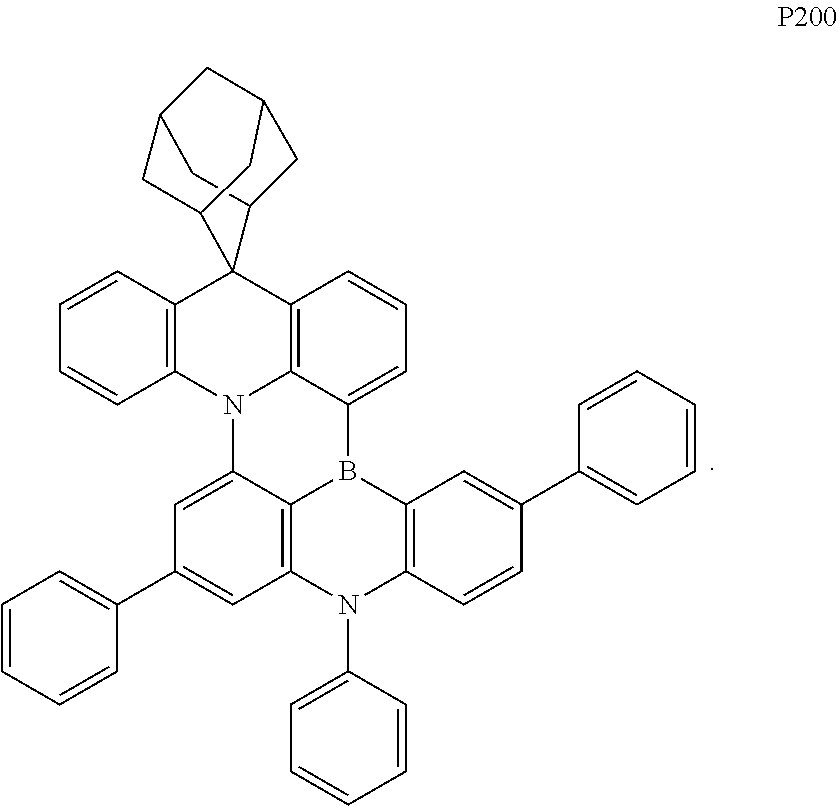
- the organic compound is selected from one or more of the following compounds P1 to P200:
- a second aspect of the present disclosure provides application of the organic compound provided by the first aspect of the present disclosure in an organic electroluminescent device.
- the organic compound can be used as an organic electroluminescent layer material of the organic electroluminescent device.
- a third aspect of the present disclosure provides an organic electroluminescent device, comprising an anode, a cathode and at least one functional layer between the anode and the cathode, wherein the functional layer includes a hole injecting layer, a hole transporting layer, an organic electroluminescent layer, an electron transporting layer and an electron injecting layer; the organic electroluminescent layer comprises the organic compound provided by the first aspect of the present disclosure, optionally comprises at least one of the compounds P1 to P184.
- the organic electroluminescent device includes an anode 100 and a cathode 200 which are oppositely disposed, and a functional layer 300 disposed between the anode 100 and the cathode 200 ; the functional layer 300 comprises the compound provided by the present disclosure.
- the compound provided by the present disclosure is used to form at least one organic film layer in the functional layer 300 to improve the life characteristics, efficiency characteristics, and reduce the driving voltage of the organic electroluminescent device.
- the mass production stability of the organic electroluminescent device can also be improved.
- the functional layer 300 includes an organic electroluminescent layer 330 , the organic electroluminescent layer 330 contains the compound provided by the present disclosure.
- the organic electroluminescent layer 330 may be composed of the compound provided by the present disclosure, or may be composed of the compound provided by the present disclosure together with other materials.
- the organic electroluminescent device includes an anode 100 , a hole injecting layer 310 , a hole transporting layer 320 , an organic electroluminescent layer 330 , an electron transporting layer 340 , an electron injecting layer 350 , and a cathode 200 which are stacked in sequence.
- the compound provided by the present disclosure may be applied to the organic electroluminescent layer 330 of the organic electroluminescent device, and can effectively improve electron transporting properties of the organic electroluminescent device.
- the anode 100 includes the following anode materials, which is preferably the material having a large work function that facilitates hole injection into the functional layer.
- the anode material include metals such as nickel, platinum, vanadium, chromium, copper, zinc, and gold or alloys thereof, metal oxides such as zinc oxide, indium oxide, indium tin oxide (ITO), and indium zinc oxide (IZO); combination of metals and oxides such as ZnO:Al or SnO 2 :Sb; or conductive polymers such as poly(3-methylthiophene), poly[3,4-(ethylene-1,2-dioxy)thiophene] (PEDT), polypyrrole, and polyaniline, but are not limited thereto.
- a transparent electrode containing indium tin oxide (ITO) as an anode is preferably included.
- the organic electroluminescent layer 330 consists of a single light-emitting material, or also contains a host material and a guest material.
- the organic electroluminescent layer 330 consists of a host material and a guest material. Holes injected into the organic electroluminescent layer 330 and electrons injected into the organic electroluminescent layer 330 may be combined in the organic electroluminescent layer 330 to form excitons, the excitons transfer energy to the host material, and the host material transfers energy to the guest material, thereby enabling the guest material to emit light.
- the guest material of the organic electroluminescent layer 330 may be a compound having a condensed aryl ring or a derivative thereof, a compound having a heteroaryl ring or a derivative thereof, an aromatic amine derivative, or other materials, which is not particularly limited in the present disclosure.
- the guest material of the organic electroluminescent layer 330 may be Ir(piq) 2 (acac).
- the guest material of the organic electroluminescent layer 330 may be BD-1, or may also be the compound provided by the present disclosure.
- the electron transporting layer 340 may be of a single-layer structure, or may also be a multi-layer structure, which may include one or more electron transporting materials.
- the electron transporting materials may be selected from a benzimidazole derivative, an oxadiazole derivative, a quinoxaline derivative, or other electron transporting materials, which is not particularly limited in the present disclosure.
- the electron transporting layer 340 may be composed of DBimiBphen and LiQ.
- the cathode 200 includes a cathode material, which is a material with a small work function that facilitates electron injection into the functional layer.
- the cathode material include metals such as magnesium, calcium, sodium, potassium, titanium, indium, yttrium, lithium, gadolinium, aluminum, silver, tin and lead or alloys thereof; or multilayer materials such as LiF/Al, Liq/Al, LiO 2 /Al, LiF/Ca, LiF/Al and BaF 2 /Ca, but not limited thereto.
- a metal electrode containing aluminium as a cathode is preferably included.
- a hole injecting layer 310 is also arranged between the anode 100 and the hole transporting layer 320 to enhance the capability of injecting holes into the hole transporting layer 320 .
- the hole injecting layer 310 may adopt a benzidine derivative, a starburst arylamine compound, a phthalocyanine derivative, or other materials, which is not particularly limited in the present disclosure.
- the hole injecting layer 310 may consist of m-MTDATA.
- the hole transporting layer 320 includes a first hole transporting layer 321 and a second hole transporting layer 322 , and the first hole transporting layer 321 is disposed to be closer to the surface of the anode 100 than the second hole transporting layer 322 ; and the first hole transporting layer 321 or the second hole transporting layer 322 comprises the organic compound provided by the present disclosure.
- one of the first hole transporting layer 321 or the second hole transporting layer 322 may contain the organic compound provided by the present disclosure, or both the first hole transporting layer 321 and the second hole transporting layer 322 may contain the organic compound provided by the present disclosure.
- the first hole transporting layer 321 or the second hole transporting layer 322 may also contain other materials or may not contain other materials.
- the second hole transporting layer 322 may be considered as an electron blocking layer of the organic electroluminescent device.
- an electron injecting layer 350 is also be disposed between the cathode 200 and the electron transporting layer 340 to enhance the capability of injecting electrons into the electron transporting layer 340 .
- the electron injecting layer 350 may include inorganic materials such as alkali metal sulfide or alkali metal halide, or may include complexs of alkali metal and organic substance.
- the electron injecting layer 350 includes LiQ.
- the organic electroluminescent device of the present disclosure is based on the excellent properties of the organic compound of the present disclosure, has good carrier conduction efficiency and life, reduces the driving voltage of the organic electroluminescent device, and improves light-emitting properties.
- nBuLi (2.5 M) (96.7 mL, 241.8 mmol) was started to be added dropwise while keeping the temperature constant, a solution of adamantanone (30 g, 199.7 mmol) in tetrahydrofuran THE (100 mL) was added dropwise into the system after stirring for 1 h, the mixture was naturally heated to room temperature after adding dropwise was finished, methanesulfonic acid (46.5 g, 483.6 mmol) was added, and the mixture was heated to reflux for 1 h under stirring.
- the organic compounds were prepared by the same method as in Synthesis Example 1 except that the raw material 1 in Table 1 was used instead of diphenylamine in step (3) in Example 1. Structures and characterization data of the finally prepared organic compounds are shown in Table 1.
- reaction was quenched by the addition of aqueous solution of ammonium chloride, and subjected to extraction with ethyl acetate to obtain the organic phase, which was dried over anhydrous magnesium sulfate and filtered, and the solvent was removed under reduced pressure.
- the resulting residue was purified by silica column chromatography purification with dichloromethane/n-heptane (1:2) to obtain Intermediate 1-A-5 (1.13 g, a yield of 44.7%) as a white solid.
- the organic compounds were prepared by the same method as in Example 9 except that the intermediates listed in Table 2 were synthesized by using a raw material 2 in Table 2 instead of p-methylaniline in step (1) in Example 9 and using a raw material 3 instead of 9-(4-bromophenyl)-9H-carbazole. Then by using the intermediates in Table 2 instead of the Intermediate I-B of step (2) in Example 9, the structures and characterization data of the finally prepared organic compounds are shown in Table 3.
- reaction was quenched by the addition of aqueous solution of ammonium chloride, and subjected to extraction with ethyl acetate to obtain the organic phase, which was dried over anhydrous magnesium sulfate and filtered, and the solvent was removed under reduced pressure.
- the resulting was purified by silica column chromatography purification with dichloromethane/n-heptane (1:2) to obtain Intermediate I-K-1 (7.13 g, a yield of 52.5%) as a white solid.
- the organic compounds were prepared by the same method as in Example 18 except that the intermediates listed in Table 4 were synthesized by using a raw material 4 in Table 4 instead of 9-fluorenone in step (1) in Example 18 and using a raw material 5 instead of 2-bromo-N-phenylaniline. Then the intermediates in Table 4 were used instead of Intermediate I-K of step (1) in Example 18. Structures and characterization data of the finally prepared compounds are shown in Table 5.
- a TOP substrate manufactured by Corning
- ITO thickness of 1500 ⁇ was cut into a dimension of 40 mm (length) ⁇ 40 mm (width) ⁇ 0.7 mm (thickness), and was prepared into an experimental substrate with a cathode overlap, an anode and an insulation layer pattern by using the photoetching process, and surface treatment was performed with UV ozone and O 2 :N 2 plasma to increase the work function of the anode (the experimental substrate) and remove scum.
- m-MTDATA (4,4′,4′′-tris(N-3-methylphenyl-N-phenylamino)triphenylamine) was subjected to vacuum evaporation on the experimental substrate (the anode) to form a hole injecting layer (HIL) having a thickness of 100 ⁇ , and NPB was subjected to vacuum evaporation on the hole injecting layer to form a first hole transporting layer (HTL1) having a thickness of 1000 ⁇ .
- HIL hole injecting layer
- HTL1 first hole transporting layer
- TCTA 4,4′,4′′-tris(carbazol-9-yl)triphenylamine
- ⁇ , ⁇ -ADN was used as a host, and doped with the organic compound P1 prepared by Synthesis Example 1, and the host and the dopant formed an organic electroluminescent layer (EML) having a thickness of 220 ⁇ according to a film thickness ratio of 30:3.
- EML organic electroluminescent layer
- DBimiBphene (4,7-Diphenyl-2,9-bis(4-(1-phenyl-1H-benzo[d]imidazol-2-yl)phenyl)-1,10-phenanthraline) and LiQ (8-hydroxyquinoline lithium) were mixed at a weight ratio of 1:1 and evaporated to form an electron transporting layer (ETL) having a thickness of 300 ⁇
- metal Yb was evaporated on the electron transporting layer to form an electron injecting layer (EIL) having a thickness of 10 ⁇
- magnesium (Mg) and silver (Ag) were mixed at an evaporation rate of 1:9 and were subjected to vacuum evaporation on the electron injecting layer to form a cathode having a thickness of 120 ⁇ .
- CPL organic capping layer
- the organic electroluminescent devices were prepared by employing the same method as in Device Example 1, except that the organic compound P1 in Device Example 1 was sequentially replaced by compounds other than compounds A to E listed in Table 8 to prepare the organic electroluminescent devices.
- the organic electroluminescent devices were prepared by employing the same method as in Device Example 1, except that compounds A to E listed below were used instead of the organic compound 1 in Device Example 1 to prepare the organic electroluminescent devices.
- the organic electroluminescent devices were prepared in the Device Examples and Device Comparative Examples were tested for IVL (Current-Voltage-Brightness) performance of the devices under conditions of 10 mA/cm 2 , and T95 lifetime of the devices was tested at 15 mA/cm 2 .
- IVL Current-Voltage-Brightness
Landscapes
- Chemical & Material Sciences (AREA)
- Engineering & Computer Science (AREA)
- Materials Engineering (AREA)
- Physics & Mathematics (AREA)
- Spectroscopy & Molecular Physics (AREA)
- Organic Chemistry (AREA)
- Optics & Photonics (AREA)
- Inorganic Chemistry (AREA)
- Electroluminescent Light Sources (AREA)
Abstract

Description

-
- wherein at least one among Q1, Q2, and Q3 is

-
- and
-
- indicates a connective bond;
- n1 and n2 are the same or different, and are respectively independently selected from 0, 1, 2, 3, or 4;
- n3 and n4 are the same or different, and are respectively independently selected from 0, 1, 2, 3, 4, or 5;
- n5 is selected from 0, 1, 2, or 3;
- R1, R2, R3, R4, and R5 are the same or different, and are respectively independently selected from deuterium, cyano, halogen, a substituted or unsubstituted alkyl having 1 to 10 carbon atoms, a substituted or unsubstituted aryl having 6 to 40 carbon atoms, a substituted or unsubstituted heteroaryl having 2 to 40 carbon atoms, and a substituted or unsubstituted arylamine having 6 to 40 carbon atoms;
- alternatively, two adjacent R1 and R2 are connected with each other to form a ring, or two adjacent R2 and R3 are connected with each other to form a ring, or two adjacent R3 and R4 are connected with each other to form a ring, or two adjacent R4 and R5 are connected with each other to form a ring, or two adjacent R1 and R4 are connected with each other to form a ring;
- the substituents of R1, R2, R3, R4, and R5 are the same or different, and are respectively independently selected from deuterium, cyano, halogen, an unsubstituted alkyl having 1 to 30 carbon atoms, an unsubstituted cycloalkyl having 3 to 30 carbon atoms, an unsubstituted heterocycloalkyl having 2 to 30 carbon atoms, an aryl having 6 to 30 carbon atoms optionally substituted with an alkyl having 1 to 5 carbon atoms, an unsubstituted heteroaryl having 1 to 30 carbon atoms, an unsubstituted alkoxy having 1 to 30 carbon atoms, an unsubstituted arylamine having 6 to 30 carbon atoms, an unsubstituted alkylsilyl having 1 to 30 carbon atoms, or an unsubstituted arylsilyl having 6 to 30 carbon atoms.
-
- 100, anode; 200, cathode; 300, functional layer; 310, hole injecting layer; 320, hole transporting layer; 321, first hole transporting layer; 322, second hole transporting layer; 330, organic electroluminescent layer; 340, electron transporting layer; 350, electron injecting layer; 400, electronic device.

-
- wherein at least one among Q1, Q2, and Q3 is

-
- indicates a connective bond;
- n1 and n2 are the same or different, and are respectively independently selected from 0, 1, 2, 3, or 4;
- n3 and n4 are the same or different, and are respectively independently selected from 0, 1, 2, 3, 4, or 5;
- n5 is selected from 0, 1, 2, or 3;
- R1, R2, R3, R4, and R5 are the same or different, and are respectively independently selected from deuterium, cyano, halogen, a substituted or unsubstituted alkyl having 1 to 10 carbon atoms, a substituted or unsubstituted aryl having 6 to 40 carbon atoms, a substituted or unsubstituted heteroaryl having 2 to 40 carbon atoms, or a substituted or unsubstituted arylamine having 6 to 40 carbon atoms;
- alternatively, two adjacent R1 and R2 are connected with each other to form a ring, or two adjacent R2 and R3 are connected with each other to form a ring, or two adjacent R3 and R4 are connected with each other to form a ring, or two adjacent R4 and R5 are connected with each other to form a ring, or two adjacent R1 and R4 are connected with each other to form a ring. It should be noted that “two adjacent R1 and R2 are connected with each other to form a ring” means that R1 and R2 may be present in a saturated or unsaturated cyclic form, or may be present independently of each other. For example, when two adjacent R1 and R2, two adjacent R2 and R3, two adjacent R3 and R4, and two adjacent R4 and R5 form rings, the ring-forming ways are, for example,


means that one of Q1, Q2, and Q3 is

or two of Q1, Q2, and Q3 are

or three of Q1, Q2, and Q3 are


”. For example, Q1 does not exist when it is not “

”, Q2 does not exist when it is not “

”, Q3 does not exist when it is not

”.

where each q is independently 0, 1, 2 or 3, and each R″ is independently selected from hydrogen, deuterium, fluorine, or chlorine” means that the formula Q-1 indicates that there are q substituents R″ on the benzene ring, each R″ may be the same or different, and the options of each R″ do not affect each other; the formula Q-2 indicates that there are q substituents R″ on each benzene ring of biphenyl, the number q of R″ substituents on both benzene rings may be the same or different from each other, each R″ may be the same or different, and the options of each R″ do not affect each other.

-
- wherein at least one among Q1, Q2, and Q3 is

-
- indicates a connective bond;
- n1 and n2 are the same or different, and are respectively independently 0, 1, 2, 3, or 4;
- n3 and n4 are the same or different, and are respectively independently 0, 1, 2, 3, 4, or 5;
- n5 is selected from 0, 1, 2, or 3;
- R1, R2, R3, R4, and R5 are the same or different, and are respectively independently selected from deuterium, cyano, halogen, an unsubstituted alkyl having 1 to 10 carbon atoms, a substituted or unsubstituted aryl having 6 to 40 carbon atoms, a substituted or unsubstituted heteroaryl having 2 to 40 carbon atoms, or a substituted or unsubstituted arylamine having 6 to 40 carbon atoms;
- the substituents of R1, R2, R3, R4, and R5 are the same or different, and are respectively independently selected from deuterium, cyano, halogen, an unsubstituted alkyl having 1 to 30 carbon atoms, an unsubstituted cycloalkyl having 3 to 30 carbon atoms, an unsubstituted heterocycloalkyl having 2 to 30 carbon atoms, a substituted or unsubstituted aryl having 6 to 30 carbon atoms, an unsubstituted heteroaryl having 1 to 30 carbon atoms, an unsubstituted alkoxy having 1 to 30 carbon atoms, an unsubstituted arylamine having 6 to 30 carbon atoms, an unsubstituted alkylsilyl having 1 to 30 carbon atoms, or an unsubstituted arylsilyl having 6 to 30 carbon atoms.

R3 and R5 form a 10-phenyl-9,10-dihydroacridine ring.
extending from a ring system, which indicates that one end of the connective bond may be connected to any position in the ring system through which the bond penetrates, and the other end is connected to the remainder of the compound molecule.


-
- wherein
-
- represents a chemical bond,
- M1 is selected from single bond or

-
- b1, b6, b7, b13 and b16 are the same or different, and are respectively independently 1, 2, 3, 4, or 5;
- b2, b3, b4, b5, b8, b9, b11, b12, b14, b17, b18 and b19 are the same or different, and are respectively independently 1, 2, 3, or 4;
- b10 is 1, 2, or 3;
- b15 is 1, 2, 3, 4, 5, 6, or 7;
- X is selected from O, S, Si(E20E21), C(E22E23), N(E24), or Se;
- Y is selected from O, S, or N(E25);
- Z1 to Z6 are the same or different, and are each independently selected from C(E′) or N, and at least one of Z1 to Z6 is N, where E′ in said Z1 to Z6 are the same or different, and are respectively independently selected from hydrogen, an alkyl having 1 to 10 carbon atoms, an aryl having 6 to 18 carbon atoms, a heteroaryl having 3 to 18 carbon atoms, or a cycloalkyl having 3 to 10 carbon atoms, or adjacent E′ may be connected to form a ring;
- E1 to E25 are the same or different, and are respectively independently selected hydrogen, deuterium, halogen, cyano, an alkyl having 1 to 10 carbon atoms, an aryl having 6 to 18 carbon atoms, a heteroaryl having 3 to 18 carbon atoms, a cycloalkyl having 3 to 10 carbon atoms, or an aryl having 6 to 18 carbon atoms substituted with alkyl; or E20 and E21 may be connected to form a ring, or E22 and E23 may be connected to form a ring, or any two E6 may be fused with the phenyl to which they are connected to form an aromatic ring, or any two E7 may be fused with phenyl to which they are connected to form an aromatic ring, where E1, E13, E14 and E19 are not aryl.

or is 6, for example

and may also be 13, for example

Of course, the number of carbon atoms forming the ring may also be other values, which will not be listed one by one here, and the number of carbon atoms in the ring is not specifically defined in the present disclosure.


| TABLE 1 | |||||
| Mass | |||||
| spec- | |||||
| Com- | trom- | ||||
| pound | etry | ||||
| Synthesis | Com- | Organic | Final | (m/z), | |
| Example | pound | Compound | Yield, | [M + | |
| No. | No. | Raw material 1 | Structure | % | H]+ |
| 3 | P2 |
 |
 |
69 | 567.3 |
| 4 | P23 |
 |
 |
72 | 609.3 |
| 5 | P33 |
 |
 |
74 | 581.3 |
| 6 | P56 |
 |
 |
60 | 609.3 |
| 7 | P73 |
 |
 |
68 | 609.3 |
| 8 | P99 |
 |
 |
69 | 651.4 |


| TABLE 2 | |||
| Inter- | |||
| medi- | |||
| ate | |||
| No. | |
|
Intermediate |
| I-C |
 |
 |
 |
| I-D |
 |
 |
|
| I-E |
 |
 |
|
| I-F |
 |
 |
 |
| I-G |
 |
|
 |
| I-H |
 |
 |
 |
| I-I |
 |
 |
 |
| I-J |
 |
 |
 |
| TABLE 3 | |||||
| Mass | |||||
| spec- | |||||
| trom- | |||||
| etry | |||||
| Synthesis | Com- | (m/z), | |||
| Example | pound | Organic Compound | Yield, | [M + | |
| No. | No. | Intermediate and Number thereof | Structure | % | H]+ |
| 10 | P128 |  |
 |
50 | 776.4 |
| 11 | P130 |  |
 |
38 | 804.4 |
| 12 | P147 |  |
 |
41 | 775.5 |
| 13 | P155 |  |
 |
43 | 761.4 |
| 14 | P157 |  |
 |
56 | 620.3 |
| 15 | P158 |  |
 |
47 | 627.3 |
| 16 | P160 |  |
 |
49 | 795.4 |
| 17 | P167 |  |
 |
32 | 878.4 |


| TABLE 4 | |||
| Intermediate | Raw material 4 | Raw material 5 | Intermediate Structure |
| I-L |
 |
 |
 |
| I-M |
 |
 |
 |
| TABLE 5 | |||||
| Mass | |||||
| spec- | |||||
| trom- | |||||
| Synthetic | Com- | etry | |||
| Example | pound | Compound | Yield, | (m/z) | |
| No. | No. | Intermediate and number thereof | Structure | % | [M + H]+ |
| 19 | P169 |  |
 |
51 | 731.3 |
| 20 | P171 |  |
 |
43 | 806.4 |


| TABLE 8 | ||||||
| Operating | External | T95 | ||||
| Device | Organic | Voltage | luminous | Quantum | device | Color |
| Example | Compound | Volt | efficacy | Efficiency EQE | lifetime | Coordinates, |
| No. | No. | (V) | (Cd/A) | (%) | (h) | CIEy |
| Example 1 | Organic | 3.92 | 6.4 | 12.7 | 167 | 0.049 |
| compound P1 | ||||||
| Example 2 | Organic | 3.93 | 6.3 | 12.7 | 165 | 0.049 |
| compound P12 | ||||||
| Example 3 | Organic | 3.95 | 6.3 | 12.9 | 170 | 0.048 |
| compound P2 | ||||||
| Example 4 | Organic | 4.01 | 6.5 | 12.6 | 164 | 0.049 |
| compound P23 | ||||||
| Example 5 | Organic | 4.00 | 6.2 | 12.0 | 172 | 0.048 |
| compound P33 | ||||||
| Example 6 | Organic | 3.99 | 6.2 | 12.9 | 173 | 0.048 |
| compound P56 | ||||||
| Example 7 | Organic | 3.93 | 6.4 | 12.7 | 165 | 0.049 |
| compound P73 | ||||||
| Example 8 | Organic | 4.01 | 6.5 | 12.6 | 166 | 0.049 |
| compound P99 | ||||||
| Example 9 | Organic | 4.01 | 6.2 | 12.0 | 170 | 0.048 |
| compound | ||||||
| P122 | ||||||
| Example 10 | Organic | 3.98 | 6.3 | 12.7 | 167 | 0.049 |
| compound | ||||||
| P128 | ||||||
| Example 11 | Organic | 3.99 | 6.5 | 12.9 | 163 | 0.048 |
| compound | ||||||
| P130 | ||||||
| Example 12 | Organic | 3.93 | 6.4 | 12.7 | 165 | 0.049 |
| compound | ||||||
| P147 | ||||||
| Example 13 | Organic | 3.96 | 6.5 | 12.6 | 163 | 0.049 |
| compound | ||||||
| P155 | ||||||
| Example 14 | Organic | 4.02 | 6.2 | 12.0 | 170 | 0.048 |
| Compound | ||||||
| P157 | ||||||
| Example 15 | Organic | 3.99 | 6.2 | 12.9 | 173 | 0.048 |
| compound | ||||||
| P158 | ||||||
| Example 16 | Organic | 3.95 | 6.4 | 12.7 | 165 | 0.049 |
| compound | ||||||
| P160 | ||||||
| Example 17 | Organic | 4.01 | 6.5 | 12.6 | 163 | 0.049 |
| compound | ||||||
| P167 | ||||||
| Example 18 | Organic | 4.01 | 6.5 | 12.6 | 161 | 0.049 |
| compound | ||||||
| P170 | ||||||
| Example 19 | Organic | 4.01 | 6.2 | 12.0 | 169 | 0.048 |
| compound | ||||||
| P169 | ||||||
| Example 20 | Organic | 3.99 | 6.4 | 12.5 | 168 | 0.048 |
| compound | ||||||
| P171 | ||||||
| Example 21 | Organic | 3.97 | 6.5 | 12.4 | 170 | 0.048 |
| compound | ||||||
| P182 | ||||||
| Comparative | Organic | 4.37 | 4.8 | 9.2 | 145 | 0.048 |
| Example 1 | Compound A | |||||
| Comparative | Organic | 4.38 | 4.4 | 11.2 | 130 | 0.049 |
| Example 2 | Compound B | |||||
| Comparative | Organic | 4.40 | 5.7 | 10.8 | 105 | 0.048 |
| Example 3 | Compound C | |||||
| Comparative | Organic | 4.41 | 4.3 | 9.7 | 123 | 0.049 |
| Example 4 | Compound D | |||||
| Comparative | Organic | 4.39 | 4.9 | 10.5 | 139 | 0.048 |
| Example 5 | Compound E | |||||
Claims (14)


Applications Claiming Priority (5)
| Application Number | Priority Date | Filing Date | Title |
|---|---|---|---|
| CN201911416572.7 | 2019-12-31 | ||
| CN201911416572 | 2019-12-31 | ||
| CN202011133615.3 | 2020-10-21 | ||
| CN202011133615.3A CN112028918B (en) | 2019-12-31 | 2020-10-21 | Organic compound, application thereof and organic electroluminescent device |
| PCT/CN2020/131873 WO2021135750A1 (en) | 2019-12-31 | 2020-11-26 | Organic compound, application thereof, and organic electroluminescent device |
Publications (2)
| Publication Number | Publication Date |
|---|---|
| US20220306655A1 US20220306655A1 (en) | 2022-09-29 |
| US12325721B2 true US12325721B2 (en) | 2025-06-10 |
Family
ID=73573326
Family Applications (1)
| Application Number | Title | Priority Date | Filing Date |
|---|---|---|---|
| US17/623,319 Active 2043-01-18 US12325721B2 (en) | 2019-12-31 | 2020-11-26 | Organic compound, application thereof, and organic electroluminescent device |
Country Status (4)
| Country | Link |
|---|---|
| US (1) | US12325721B2 (en) |
| KR (1) | KR102631942B1 (en) |
| CN (1) | CN112028918B (en) |
| WO (1) | WO2021135750A1 (en) |
Families Citing this family (8)
| Publication number | Priority date | Publication date | Assignee | Title |
|---|---|---|---|---|
| KR102213030B1 (en) * | 2018-11-19 | 2021-02-08 | 에스에프씨주식회사 | Novel boron compounds and Organic light emitting diode including the same |
| WO2021187507A1 (en) * | 2020-03-18 | 2021-09-23 | 株式会社Kyulux | Compound, light-emitting material, and organic light-emitting device |
| KR102877612B1 (en) * | 2020-05-07 | 2025-10-29 | 삼성디스플레이 주식회사 | Heterocyclic compound and light emitting device including the same |
| KR102859213B1 (en) * | 2020-06-09 | 2025-09-12 | 삼성디스플레이 주식회사 | Heterocyclic compound and light emitting device including the same |
| CN113045595A (en) * | 2021-02-05 | 2021-06-29 | 吉林奥来德光电材料股份有限公司 | Polycyclic aromatic compound, preparation method thereof, light-emitting material, light-emitting layer and organic electroluminescent device |
| JP7790162B2 (en) * | 2021-07-12 | 2025-12-23 | 東レ株式会社 | Compound, light-emitting element using the same, and color-converting composition |
| WO2024012365A1 (en) * | 2022-07-14 | 2024-01-18 | 清华大学 | Organic compound and use thereof |
| KR20240049743A (en) * | 2022-10-07 | 2024-04-17 | 삼성디스플레이 주식회사 | Light emitting device including organometallic compound, electronic apparatus and electronic equipment including the light emitting device and the organometallic compound |
Citations (22)
| Publication number | Priority date | Publication date | Assignee | Title |
|---|---|---|---|---|
| CN105308026A (en) | 2013-07-09 | 2016-02-03 | 东曹株式会社 | Cyclic azine compound having adamantyl group, production method, and organic electroluminescent element containing said compound as constituent |
| CN106467553A (en) | 2016-07-29 | 2017-03-01 | 江苏三月光电科技有限公司 | A boron-containing organic electroluminescent compound and its application in OLED devices |
| WO2017195669A1 (en) | 2016-05-13 | 2017-11-16 | コニカミノルタ株式会社 | Organic electroluminescence element material, organic electroluminescence element, display apparatus and illumination apparatus |
| WO2018150832A1 (en) | 2017-02-16 | 2018-08-23 | 学校法人関西学院 | Organic electroluminescence element |
| WO2018186396A1 (en) | 2017-04-03 | 2018-10-11 | 出光興産株式会社 | Organic electroluminescence element and electronic apparatus |
| KR20180127918A (en) | 2017-05-22 | 2018-11-30 | 머티어리얼사이언스 주식회사 | Organic compound and organic electroluminescent device comprising the same |
| WO2019004247A1 (en) | 2017-06-30 | 2019-01-03 | 住友化学株式会社 | Light emitting element and polymer compound which is useful for production of same |
| CN109438350A (en) | 2018-11-19 | 2019-03-08 | 深圳市华星光电技术有限公司 | Small organic molecule luminescent material and organic electroluminescence device |
| CN109575059A (en) | 2018-12-19 | 2019-04-05 | 武汉华星光电半导体显示技术有限公司 | Thermal activation delayed fluorescence material, preparation method and electroluminescent device |
| CN109593042A (en) | 2018-12-24 | 2019-04-09 | 陕西莱特迈思光电材料有限公司 | A kind of electroluminescent organic material and the organic electroluminescence device comprising it |
| WO2019074093A1 (en) | 2017-10-13 | 2019-04-18 | 学校法人関西学院 | Polycyclic aromatic dimeric compound |
| CN110028459A (en) | 2019-05-24 | 2019-07-19 | 上海天马有机发光显示技术有限公司 | Compound, display panel and display device |
| CN110128279A (en) | 2019-06-14 | 2019-08-16 | 陕西莱特光电材料股份有限公司 | Electroluminescent organic material and organic electroluminescence device comprising the material |
| CN110156756A (en) | 2019-05-27 | 2019-08-23 | 上海天马有机发光显示技术有限公司 | Compound, display panel and display device |
| WO2019162332A1 (en) | 2018-02-20 | 2019-08-29 | Cynora Gmbh | Organic molecules for optoelectronic devices |
| CN110183333A (en) | 2019-06-19 | 2019-08-30 | 陕西莱特光电材料股份有限公司 | A kind of electroluminescent organic material and the organic electroluminescence device comprising the material |
| US20190280209A1 (en) | 2018-03-08 | 2019-09-12 | Jnc Corporation | Organic electroluminescent element |
| WO2019194298A1 (en) | 2018-04-05 | 2019-10-10 | 出光興産株式会社 | Organic electroluminescence element and electronic device |
| WO2019198699A1 (en) | 2018-04-12 | 2019-10-17 | 学校法人関西学院 | Cycloalkyl-substituted polycyclic aromatic compound |
| CN110563647A (en) | 2019-08-27 | 2019-12-13 | 陕西莱特光电材料股份有限公司 | nitrogen-containing compound, organic electroluminescent device, and photoelectric conversion device |
| US20200223873A1 (en) * | 2017-09-12 | 2020-07-16 | Cynora Gmbh | Organic molecules for use in optoelectronic devices |
| US20230104248A1 (en) * | 2019-12-19 | 2023-04-06 | Merck Patent Gmbh | Polycyclic compounds for organic electroluminescent devices |
-
2020
- 2020-10-21 CN CN202011133615.3A patent/CN112028918B/en active Active
- 2020-11-26 WO PCT/CN2020/131873 patent/WO2021135750A1/en not_active Ceased
- 2020-11-26 US US17/623,319 patent/US12325721B2/en active Active
- 2020-11-26 KR KR1020217043405A patent/KR102631942B1/en active Active
Patent Citations (22)
| Publication number | Priority date | Publication date | Assignee | Title |
|---|---|---|---|---|
| CN105308026A (en) | 2013-07-09 | 2016-02-03 | 东曹株式会社 | Cyclic azine compound having adamantyl group, production method, and organic electroluminescent element containing said compound as constituent |
| WO2017195669A1 (en) | 2016-05-13 | 2017-11-16 | コニカミノルタ株式会社 | Organic electroluminescence element material, organic electroluminescence element, display apparatus and illumination apparatus |
| CN106467553A (en) | 2016-07-29 | 2017-03-01 | 江苏三月光电科技有限公司 | A boron-containing organic electroluminescent compound and its application in OLED devices |
| WO2018150832A1 (en) | 2017-02-16 | 2018-08-23 | 学校法人関西学院 | Organic electroluminescence element |
| WO2018186396A1 (en) | 2017-04-03 | 2018-10-11 | 出光興産株式会社 | Organic electroluminescence element and electronic apparatus |
| KR20180127918A (en) | 2017-05-22 | 2018-11-30 | 머티어리얼사이언스 주식회사 | Organic compound and organic electroluminescent device comprising the same |
| WO2019004247A1 (en) | 2017-06-30 | 2019-01-03 | 住友化学株式会社 | Light emitting element and polymer compound which is useful for production of same |
| US20200223873A1 (en) * | 2017-09-12 | 2020-07-16 | Cynora Gmbh | Organic molecules for use in optoelectronic devices |
| WO2019074093A1 (en) | 2017-10-13 | 2019-04-18 | 学校法人関西学院 | Polycyclic aromatic dimeric compound |
| WO2019162332A1 (en) | 2018-02-20 | 2019-08-29 | Cynora Gmbh | Organic molecules for optoelectronic devices |
| US20190280209A1 (en) | 2018-03-08 | 2019-09-12 | Jnc Corporation | Organic electroluminescent element |
| WO2019194298A1 (en) | 2018-04-05 | 2019-10-10 | 出光興産株式会社 | Organic electroluminescence element and electronic device |
| WO2019198699A1 (en) | 2018-04-12 | 2019-10-17 | 学校法人関西学院 | Cycloalkyl-substituted polycyclic aromatic compound |
| CN109438350A (en) | 2018-11-19 | 2019-03-08 | 深圳市华星光电技术有限公司 | Small organic molecule luminescent material and organic electroluminescence device |
| CN109575059A (en) | 2018-12-19 | 2019-04-05 | 武汉华星光电半导体显示技术有限公司 | Thermal activation delayed fluorescence material, preparation method and electroluminescent device |
| CN109593042A (en) | 2018-12-24 | 2019-04-09 | 陕西莱特迈思光电材料有限公司 | A kind of electroluminescent organic material and the organic electroluminescence device comprising it |
| CN110028459A (en) | 2019-05-24 | 2019-07-19 | 上海天马有机发光显示技术有限公司 | Compound, display panel and display device |
| CN110156756A (en) | 2019-05-27 | 2019-08-23 | 上海天马有机发光显示技术有限公司 | Compound, display panel and display device |
| CN110128279A (en) | 2019-06-14 | 2019-08-16 | 陕西莱特光电材料股份有限公司 | Electroluminescent organic material and organic electroluminescence device comprising the material |
| CN110183333A (en) | 2019-06-19 | 2019-08-30 | 陕西莱特光电材料股份有限公司 | A kind of electroluminescent organic material and the organic electroluminescence device comprising the material |
| CN110563647A (en) | 2019-08-27 | 2019-12-13 | 陕西莱特光电材料股份有限公司 | nitrogen-containing compound, organic electroluminescent device, and photoelectric conversion device |
| US20230104248A1 (en) * | 2019-12-19 | 2023-04-06 | Merck Patent Gmbh | Polycyclic compounds for organic electroluminescent devices |
Non-Patent Citations (2)
| Title |
|---|
| International Search Report from corresponding International Application No. PCT/CN2020/131873, mailed on Mar. 3, 2021, 6 pages. |
| Office Action from corresponding Korean Application No. 10-2021-7043405; dated Oct. 17, 2023, 10 pages with translation. |
Also Published As
| Publication number | Publication date |
|---|---|
| WO2021135750A1 (en) | 2021-07-08 |
| CN112028918B (en) | 2023-04-28 |
| KR102631942B1 (en) | 2024-02-01 |
| KR20220007702A (en) | 2022-01-18 |
| CN112028918A (en) | 2020-12-04 |
| US20220306655A1 (en) | 2022-09-29 |
Similar Documents
| Publication | Publication Date | Title |
|---|---|---|
| US12325721B2 (en) | Organic compound, application thereof, and organic electroluminescent device | |
| US11827615B2 (en) | Nitrogen-containing compound, electronic element and electronic device | |
| US11718583B2 (en) | Nitrogen-containing compound, electronic component using same and electronic device | |
| US11444252B2 (en) | Nitrogen-containing compound, organic electroluminescent device and electronic apparatus | |
| US20230322656A1 (en) | Organic compound, and electronic component and electronic device having same | |
| US12144247B2 (en) | Organic compound and electronic device and electronic apparatus thereof | |
| US20230146030A1 (en) | Arylamine compound, electronic component using same and electronic device | |
| US20230269958A1 (en) | Organic compound, and electronic component and electronic device having same | |
| US20230200224A1 (en) | Nitrogen-containing compound, and electronic element and electronic device having same | |
| US11492314B2 (en) | Organic compound, organic electroluminescent device and electronic apparatus | |
| US11482677B2 (en) | Compound and organic electronic device comprising same | |
| US12120950B2 (en) | Organic compound, electronic element and electronic apparatus | |
| US12108660B2 (en) | Organic compound, electronic component, and electronic apparatus | |
| US11849637B2 (en) | Nitrogen-containing compound, electronic component comprising same, and electronic apparatus | |
| US20220388944A1 (en) | Nitrogen-containing compound, organic electroluminescent device, and electronic apparatus | |
| US11098022B2 (en) | Nitrogen-containing compound, electronic component and electronic device | |
| US20240196746A1 (en) | Organic compound, organic electroluminescent device, and electronic apparatus | |
| US20250109091A1 (en) | Nitrogen-containing compound, electronic element, and electronic device | |
| US20240217956A1 (en) | Organic compounds, organic electroluminescent device and electronic apparatus | |
| US20230320205A1 (en) | Nitrogen-containing compound, organic electroluminescent device, and electronic apparatus | |
| US20230183191A1 (en) | Nitrogen-containing compound, electronic element, and electronic device | |
| US11450818B2 (en) | Organic compound, use thereof and organic electroluminescent device using same | |
| US12048240B2 (en) | Organic compound, electronic component and electronic apparatus comprising the same | |
| US11535602B1 (en) | Nitrogen-containing compound, electronic element and electronic apparatus | |
| US12338217B2 (en) | Nitrogen-containing compound, electronic element and electronic device |
Legal Events
| Date | Code | Title | Description |
|---|---|---|---|
| AS | Assignment |
Owner name: SHAANXI LIGHTE OPTOELECTRONICS MATERIAL CO., LTD., CHINA Free format text: ASSIGNMENT OF ASSIGNORS INTEREST;ASSIGNORS:NIE, QIQI;MA, TIANTIAN;CAO, JIAMEI;REEL/FRAME:058489/0898 Effective date: 20211207 |
|
| FEPP | Fee payment procedure |
Free format text: ENTITY STATUS SET TO UNDISCOUNTED (ORIGINAL EVENT CODE: BIG.); ENTITY STATUS OF PATENT OWNER: SMALL ENTITY |
|
| STPP | Information on status: patent application and granting procedure in general |
Free format text: APPLICATION UNDERGOING PREEXAM PROCESSING |
|
| FEPP | Fee payment procedure |
Free format text: ENTITY STATUS SET TO SMALL (ORIGINAL EVENT CODE: SMAL); ENTITY STATUS OF PATENT OWNER: SMALL ENTITY |
|
| STPP | Information on status: patent application and granting procedure in general |
Free format text: DOCKETED NEW CASE - READY FOR EXAMINATION |
|
| STPP | Information on status: patent application and granting procedure in general |
Free format text: NOTICE OF ALLOWANCE MAILED -- APPLICATION RECEIVED IN OFFICE OF PUBLICATIONS |
|
| STCF | Information on status: patent grant |
Free format text: PATENTED CASE |