US12319273B2 - Turning behavior control device for vehicle - Google Patents
Turning behavior control device for vehicle Download PDFInfo
- Publication number
- US12319273B2 US12319273B2 US18/363,436 US202318363436A US12319273B2 US 12319273 B2 US12319273 B2 US 12319273B2 US 202318363436 A US202318363436 A US 202318363436A US 12319273 B2 US12319273 B2 US 12319273B2
- Authority
- US
- United States
- Prior art keywords
- turning
- wheels
- rear wheel
- front wheel
- turning inner
- Prior art date
- Legal status (The legal status is an assumption and is not a legal conclusion. Google has not performed a legal analysis and makes no representation as to the accuracy of the status listed.)
- Active, expires
Links
Images


Classifications
-
- B—PERFORMING OPERATIONS; TRANSPORTING
- B60—VEHICLES IN GENERAL
- B60W—CONJOINT CONTROL OF VEHICLE SUB-UNITS OF DIFFERENT TYPE OR DIFFERENT FUNCTION; CONTROL SYSTEMS SPECIALLY ADAPTED FOR HYBRID VEHICLES; ROAD VEHICLE DRIVE CONTROL SYSTEMS FOR PURPOSES NOT RELATED TO THE CONTROL OF A PARTICULAR SUB-UNIT
- B60W30/00—Purposes of road vehicle drive control systems not related to the control of a particular sub-unit, e.g. of systems using conjoint control of vehicle sub-units
- B60W30/02—Control of vehicle driving stability
- B60W30/045—Improving turning performance
-
- B—PERFORMING OPERATIONS; TRANSPORTING
- B60—VEHICLES IN GENERAL
- B60W—CONJOINT CONTROL OF VEHICLE SUB-UNITS OF DIFFERENT TYPE OR DIFFERENT FUNCTION; CONTROL SYSTEMS SPECIALLY ADAPTED FOR HYBRID VEHICLES; ROAD VEHICLE DRIVE CONTROL SYSTEMS FOR PURPOSES NOT RELATED TO THE CONTROL OF A PARTICULAR SUB-UNIT
- B60W30/00—Purposes of road vehicle drive control systems not related to the control of a particular sub-unit, e.g. of systems using conjoint control of vehicle sub-units
- B60W30/18—Propelling the vehicle
- B60W30/18009—Propelling the vehicle related to particular drive situations
- B60W30/18145—Cornering
-
- B—PERFORMING OPERATIONS; TRANSPORTING
- B60—VEHICLES IN GENERAL
- B60W—CONJOINT CONTROL OF VEHICLE SUB-UNITS OF DIFFERENT TYPE OR DIFFERENT FUNCTION; CONTROL SYSTEMS SPECIALLY ADAPTED FOR HYBRID VEHICLES; ROAD VEHICLE DRIVE CONTROL SYSTEMS FOR PURPOSES NOT RELATED TO THE CONTROL OF A PARTICULAR SUB-UNIT
- B60W10/00—Conjoint control of vehicle sub-units of different type or different function
- B60W10/04—Conjoint control of vehicle sub-units of different type or different function including control of propulsion units
-
- B—PERFORMING OPERATIONS; TRANSPORTING
- B60—VEHICLES IN GENERAL
- B60W—CONJOINT CONTROL OF VEHICLE SUB-UNITS OF DIFFERENT TYPE OR DIFFERENT FUNCTION; CONTROL SYSTEMS SPECIALLY ADAPTED FOR HYBRID VEHICLES; ROAD VEHICLE DRIVE CONTROL SYSTEMS FOR PURPOSES NOT RELATED TO THE CONTROL OF A PARTICULAR SUB-UNIT
- B60W10/00—Conjoint control of vehicle sub-units of different type or different function
- B60W10/18—Conjoint control of vehicle sub-units of different type or different function including control of braking systems
- B60W10/184—Conjoint control of vehicle sub-units of different type or different function including control of braking systems with wheel brakes
- B60W10/188—Conjoint control of vehicle sub-units of different type or different function including control of braking systems with wheel brakes hydraulic brakes
-
- B—PERFORMING OPERATIONS; TRANSPORTING
- B60—VEHICLES IN GENERAL
- B60W—CONJOINT CONTROL OF VEHICLE SUB-UNITS OF DIFFERENT TYPE OR DIFFERENT FUNCTION; CONTROL SYSTEMS SPECIALLY ADAPTED FOR HYBRID VEHICLES; ROAD VEHICLE DRIVE CONTROL SYSTEMS FOR PURPOSES NOT RELATED TO THE CONTROL OF A PARTICULAR SUB-UNIT
- B60W40/00—Estimation or calculation of non-directly measurable driving parameters for road vehicle drive control systems not related to the control of a particular sub unit, e.g. by using mathematical models
- B60W40/10—Estimation or calculation of non-directly measurable driving parameters for road vehicle drive control systems not related to the control of a particular sub unit, e.g. by using mathematical models related to vehicle motion
- B60W40/114—Yaw movement
-
- B—PERFORMING OPERATIONS; TRANSPORTING
- B60—VEHICLES IN GENERAL
- B60W—CONJOINT CONTROL OF VEHICLE SUB-UNITS OF DIFFERENT TYPE OR DIFFERENT FUNCTION; CONTROL SYSTEMS SPECIALLY ADAPTED FOR HYBRID VEHICLES; ROAD VEHICLE DRIVE CONTROL SYSTEMS FOR PURPOSES NOT RELATED TO THE CONTROL OF A PARTICULAR SUB-UNIT
- B60W2510/00—Input parameters relating to a particular sub-units
- B60W2510/20—Steering systems
- B60W2510/207—Oversteer or understeer
-
- B—PERFORMING OPERATIONS; TRANSPORTING
- B60—VEHICLES IN GENERAL
- B60W—CONJOINT CONTROL OF VEHICLE SUB-UNITS OF DIFFERENT TYPE OR DIFFERENT FUNCTION; CONTROL SYSTEMS SPECIALLY ADAPTED FOR HYBRID VEHICLES; ROAD VEHICLE DRIVE CONTROL SYSTEMS FOR PURPOSES NOT RELATED TO THE CONTROL OF A PARTICULAR SUB-UNIT
- B60W2520/00—Input parameters relating to overall vehicle dynamics
- B60W2520/10—Longitudinal speed
-
- B—PERFORMING OPERATIONS; TRANSPORTING
- B60—VEHICLES IN GENERAL
- B60W—CONJOINT CONTROL OF VEHICLE SUB-UNITS OF DIFFERENT TYPE OR DIFFERENT FUNCTION; CONTROL SYSTEMS SPECIALLY ADAPTED FOR HYBRID VEHICLES; ROAD VEHICLE DRIVE CONTROL SYSTEMS FOR PURPOSES NOT RELATED TO THE CONTROL OF A PARTICULAR SUB-UNIT
- B60W2520/00—Input parameters relating to overall vehicle dynamics
- B60W2520/14—Yaw
-
- B—PERFORMING OPERATIONS; TRANSPORTING
- B60—VEHICLES IN GENERAL
- B60W—CONJOINT CONTROL OF VEHICLE SUB-UNITS OF DIFFERENT TYPE OR DIFFERENT FUNCTION; CONTROL SYSTEMS SPECIALLY ADAPTED FOR HYBRID VEHICLES; ROAD VEHICLE DRIVE CONTROL SYSTEMS FOR PURPOSES NOT RELATED TO THE CONTROL OF A PARTICULAR SUB-UNIT
- B60W2720/00—Output or target parameters relating to overall vehicle dynamics
- B60W2720/14—Yaw
-
- B—PERFORMING OPERATIONS; TRANSPORTING
- B60—VEHICLES IN GENERAL
- B60W—CONJOINT CONTROL OF VEHICLE SUB-UNITS OF DIFFERENT TYPE OR DIFFERENT FUNCTION; CONTROL SYSTEMS SPECIALLY ADAPTED FOR HYBRID VEHICLES; ROAD VEHICLE DRIVE CONTROL SYSTEMS FOR PURPOSES NOT RELATED TO THE CONTROL OF A PARTICULAR SUB-UNIT
- B60W2720/00—Output or target parameters relating to overall vehicle dynamics
- B60W2720/30—Wheel torque
-
- B—PERFORMING OPERATIONS; TRANSPORTING
- B60—VEHICLES IN GENERAL
- B60W—CONJOINT CONTROL OF VEHICLE SUB-UNITS OF DIFFERENT TYPE OR DIFFERENT FUNCTION; CONTROL SYSTEMS SPECIALLY ADAPTED FOR HYBRID VEHICLES; ROAD VEHICLE DRIVE CONTROL SYSTEMS FOR PURPOSES NOT RELATED TO THE CONTROL OF A PARTICULAR SUB-UNIT
- B60W2720/00—Output or target parameters relating to overall vehicle dynamics
- B60W2720/40—Torque distribution
- B60W2720/403—Torque distribution between front and rear axle
-
- B—PERFORMING OPERATIONS; TRANSPORTING
- B60—VEHICLES IN GENERAL
- B60W—CONJOINT CONTROL OF VEHICLE SUB-UNITS OF DIFFERENT TYPE OR DIFFERENT FUNCTION; CONTROL SYSTEMS SPECIALLY ADAPTED FOR HYBRID VEHICLES; ROAD VEHICLE DRIVE CONTROL SYSTEMS FOR PURPOSES NOT RELATED TO THE CONTROL OF A PARTICULAR SUB-UNIT
- B60W2720/00—Output or target parameters relating to overall vehicle dynamics
- B60W2720/40—Torque distribution
- B60W2720/406—Torque distribution between left and right wheel
Definitions
- the present disclosure relates to a turning behavior control device for a vehicle that efficiently reduces understeer when a high degree of understeer is detected during turning.
- travel trajectory control also referred to as “lane keeping control” as automatic steering control
- steered wheels are steered, and feedback control is performed such that the actual travel trajectory converges to the target travel trajectory.
- a steering control device attempts to steer the steered wheels in a turning-increasing direction to correct the turning radius to the turning radius set as the target travel trajectory.
- JP-A Japanese Unexamined Patent Application Publication
- JP2020-050024 discloses a technique in which, when a deviation between a reference yaw rate (target yaw rate) of a vehicle and an actual yaw rate exceeds a predetermined deviation reference value and a time change rate of the deviation exceeds a start reference value during turning, a braking force is applied to a turning inner-side drive wheel and load transfer from a turning outer-side drive wheel to the turning inner-side drive wheel is generated, thereby increasing a ground contact load of the turning inner-side drive wheel.
- target yaw rate target yaw rate
- time change rate of the deviation exceeds a start reference value during turning
- An aspect of the present disclosure provides a turning behavior control device for a vehicle in which left and right front wheels are steered wheels.
- the turning behavior control device includes a yaw rate detection unit, a brake unit, a drive source, a travel control unit.
- the yaw rate detection unit is configured to detect an actual yaw rate acting on a vehicle.
- the brake unit is configured to independently apply a braking force to the left and right front wheels and left and right rear wheels.
- the drive source is configured to drive the left and right front wheels and the left and right rear wheels.
- the travel control unit configured to control the braking force of the brake unit and an output of the drive source.
- the travel control unit includes a deviation value calculation unit configured to calculate a deviation between a reference yaw rate for determining the degree of understeer during turning of the vehicle and the actual yaw rate detected by the yaw rate detection unit, a braking force control unit configured to output, to the brake unit, a first signal for applying the braking force to one of a turning inner-side rear wheel and a turning inner-side front wheel when determining that the deviation calculated by the deviation value calculation unit exceeds a predetermined deviation reference value, and a driving force control unit configured to output, to the drive source, a signal for applying a driving force to one of a turning outer-side rear wheel and a turning outer-side front wheel when the braking force control unit outputs the first signal.
- FIG. 1 is a schematic configuration diagram of a driving assistance device
- FIG. 2 is a flowchart showing a turning behavior control routine
- FIG. 3 is an explanatory diagram showing load transfer when four wheels are not driven and a turning inner-side front wheel is braked;
- FIG. 4 is an explanatory diagram showing load transfer when four wheels are not driven and a turning inner-side rear wheel is braked;
- FIG. 5 is an explanatory diagram showing load transfer when four wheels are not driven and a turning outer-side front wheel is braked;
- FIG. 6 is an explanatory diagram showing load transfer when four wheels are not driven and a turning outer-side rear wheel is braked;
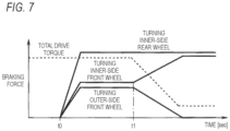
- FIG. 7 is a time chart showing changes in a braking force and a total drive torque applied to the turning inner-side front and rear wheels and the turning outer-side front wheel immediately after a high degree of understeer is detected;
- FIG. 8 is an explanatory diagram showing load transfer when only the turning inner-side front wheel is driven
- FIG. 9 is an explanatory diagram showing load transfer when only the turning inner-side rear wheel is driven.
- FIG. 10 is an explanatory diagram showing load transfer when only the turning outer-side front wheel is driven
- FIG. 11 is an explanatory diagram showing load transfer when only the turning outer-side rear wheel is driven
- FIG. 12 is an explanatory diagram showing a state in which rear wheels are drive wheels and the turning inner-side rear wheel is braked;
- FIG. 13 is an explanatory diagram showing a state in which rear wheels are drive wheels and the turning inner-side front and rear wheels are braked;
- FIG. 14 is an explanatory diagram showing a state in which front wheels are drive wheels and the turning inner-side front and rear wheels are braked;
- FIG. 15 is an explanatory diagram showing a state in which the turning inner-side rear wheel is braked and the turning outer-side rear wheel is driven;
- FIG. 16 is an explanatory diagram showing a state in which the turning inner-side front wheel is braked and the turning outer-side rear wheel is driven;
- FIG. 17 is an explanatory diagram showing a state in which the turning outer-side front wheel is driven and the turning inner-side rear wheel is braked, and
- FIG. 18 is an explanatory diagram showing a state in which the turning inner-side front wheel is braked and the turning outer-side front wheel is driven.
- the degree of understeer in an initial stage in which a high degree of understeer is detected, by applying transient load transfer to the turning inner-side drive wheel, the degree of understeer can be efficiently reduced.
- JP-A No. JP2020-050024 when a high degree of understeer is detected, a constant braking force is continuously applied to the turning inner-side drive wheel, and static load transfer is simply generated from the turning outer-side drive wheel to the turning inner-side drive wheel, and therefore, it may be difficult to efficiently reduce the degree of understeer in the initial stage. As a result, a delay occurs in the control for reducing the degree of understeer, which may make occupants including a driver uncomfortable.
- a vehicle M shown in FIG. 1 is a four-wheel drive vehicle in which front wheels Fl, Fr and rear wheels Rl, Rr, which are steered wheels, are driven by different drive sources (engines or electric motors) 1 and 6 .
- An output shaft 1 a of a front drive source (FPU) 1 is coupled to drive shafts (front wheel drive shafts) 3 l , 3 r of the front wheels Fl, Fr via a front differential 2 .
- An output shaft 6 a of a rear drive source (RPU) 6 is coupled to drive shafts (rear wheel drive shafts) 8 l , 8 r of the rear wheels Rl, Rr via a rear differential 7 .
- left and right front wheels Fl, Fr are respectively supported by front wheel suspensions
- left and right rear wheels Rl, Rr are respectively supported by rear wheel suspensions.
- the left and right front wheels Fl, Fr and the left and right rear wheels Rl, Rr are each provided with a hydraulic brake mechanism 9 .
- the hydraulic brake mechanism 9 is a well-known friction brake device such as a disc brake or a drum brake, and a piston of a wheel cylinder of the hydraulic brake mechanism 9 is operated by a hydraulic brake pressure supplied from a hydraulic control unit (HCU) 11 as a brake unit to apply a hydraulic braking (friction braking) force.
- HCU hydraulic control unit
- the HCU 11 includes actuators and valves such as a hydraulic pressure generating device including a booster pump, an accumulator, and the like, a pressure control valve that adjusts a hydraulic pressure during brake differential operation and supplies the adjusted hydraulic pressure to the wheel cylinder of the hydraulic brake mechanism 9 , and an opening and closing control valve that opens and closes a hydraulic circuit that supplies the hydraulic brake pressure to the hydraulic brake mechanism 9 .
- actuators and valves such as a hydraulic pressure generating device including a booster pump, an accumulator, and the like, a pressure control valve that adjusts a hydraulic pressure during brake differential operation and supplies the adjusted hydraulic pressure to the wheel cylinder of the hydraulic brake mechanism 9 , and an opening and closing control valve that opens and closes a hydraulic circuit that supplies the hydraulic brake pressure to the hydraulic brake mechanism 9 .
- the front drive source 1 , the rear drive source 6 , and the HCU 11 are operated by a control signal from a travel control unit 12 as a travel control unit.
- the travel control unit 12 includes a microcontroller provided with a CPU, a RAM, a ROM, a rewritable nonvolatile memory (flash memory or EEPROM), and peripheral devices.
- the ROM stores programs, fixed data, and the like necessary for the CPU to execute various types of processing.
- the RAM is provided as a work area of the CPU and temporarily stores various types of data in the CPU.
- the CPU is also called a microprocessor (MPU) or a processor.
- a graphics processing unit (GPU) or a graph streaming processor (GSP) may be used.
- the CPU, the GPU, and the GSP may be selectively used in combination.
- the travel control unit 12 has a turning behavior control function of restoring a ground contact load of the turning inner-side front wheel and increasing a lateral force of the turning inner-side front wheel to reduce the degree of understeer.
- Sensors that detect a driving state of the vehicle M such as a steering angle sensor 21 that detects a steering angle of the left and right front wheels Fl, Fr, a vehicle speed sensor 22 that detects a vehicle speed (host vehicle speed) of the vehicle M, a yaw rate sensor 23 serving as a yaw rate detection unit that detects an actual yaw rate acting on a vehicle body, torque sensors 24 a , 24 b that individually detect shaft torques acting on the output shafts 1 a , 6 a of the drive sources 1 , 6 , and the like are coupled to an input side of the travel control unit 12 .
- a braking force or a driving force is selectively applied to the wheels Fl, Fr, Rl, Rr according to a traveling state of the vehicle M to reduce the degree of understeer.
- the braking force and the driving force may be collectively referred to as a “braking/driving force”.
- the travel control unit 12 can apply a braking (regenerative braking) force to the wheels by a regenerative operation of the electric motor. Further, the travel control unit 12 can apply a braking force to the wheels driven by the electric motor through the cooperation of friction braking and regenerative braking. In this case, the electric motor serves as a brake unit.
- the front wheel suspensions have an anti-dive geometry
- the rear wheel suspensions have an anti-lift geometry. That is, instantaneous centers of the left and right front wheels Fl, Fr suspended from the vehicle body by the left and right front wheel suspensions are set to be located above ground contact points of the left and right front wheels Fl, Fr and on a rear side of the vehicle body. Therefore, the left and right front wheel suspensions have the anti-dive geometry.
- a braking force when a braking force is applied to a turning outer-side front wheel, an upward force is generated on a turning outer side of a front portion of the vehicle body of the vehicle M, the roll of the vehicle body is prevented, and the ground contact load of the turning inner-side front wheel further increases.
- a braking force is applied to a turning outer-side rear wheel, a downward force is generated on a turning outer side of a rear portion of the vehicle body, and the ground contact load of the turning inner-side front wheel located diagonally cannot be sufficiently increased.
- step S 1 sensor outputs such as a steering angle detected by the steering angle sensor 21 , a vehicle speed detected by the vehicle speed sensor 22 , and an actual yaw rate detected by the yaw rate sensor 23 are read.
- step S 2 a reference yaw rate acting on the vehicle M is calculated based on the steering angle and the vehicle speed, and a yaw rate deviation ⁇ Yr is obtained based on a difference between the reference yaw rate and the actual yaw rate detected by the yaw rate sensor 23 .
- the processing in step S 2 corresponds to a deviation value calculation unit of the present disclosure.
- step S 3 it is checked whether the vehicle M is in a non-braking state and is turning. Whether the vehicle M is in the non-braking state is determined based on whether a braking signal is output from the travel control unit 12 to the HCU 11 . Whether the vehicle M is turning is determined based on an output value of the yaw rate sensor 23 .
- step S 4 When it is determined that the vehicle M is in the non-braking state and is turning, the process proceeds to step S 4 .
- the routine is exited.
- the deviation reference value Yrc is a reference value for checking whether the degree of understeer occurring in the vehicle M is high, and is set in advance based on an experiment or the like.
- step S 5 a target yaw moment Myt for ensuring the traveling stability of the vehicle M is obtained based on the yaw rate deviation ⁇ Yr by referring to a map or the like.
- step S 6 a target deceleration Gxt for reducing a current yaw moment to the target yaw moment Myt is obtained.
- step S 7 in which it is determined to which of the wheels Fl, Fr, Rl, and Rr a braking/driving force is applied based on the target yaw moment Myt and the target deceleration Gxt, and a target braking force Fbti or a target driving force Fdti of the wheels Fl, Fr, Rl, and Rr to which the braking/driving force is applied is obtained.
- the processing in steps S 4 to S 8 corresponds to a braking force control unit and a driving force control unit of the present disclosure.
- Load transfer amounts in a roll direction that is, a load transfer amount ⁇ W f from the turning inner-side front wheel (Fl) to the turning outer-side front wheel (Fr) and a load transfer amount ⁇ W r from a turning inner-side rear wheel (Rl) to the turning outer-side rear wheel (Rr) are expressed by the following formula (1) and (2):
- ⁇ f is an angle formed by a line segment connecting a ground contact point and an instantaneous center of the left front wheel Fl and the right front wheel Fr in a neutral position with respect to a horizontal direction
- the angle ⁇ f is an anti-dive angle when the left front wheel Fl and the right front wheel Fr are in the neutral position
- ⁇ r is an angle formed by a line segment connecting a ground contact point and an instantaneous center of the left rear wheel Rl and the right rear wheel Rr in a neutral position with respect to the horizontal direction
- the angle ⁇ r is an anti-lift angle when the left rear wheel Rl and the right rear wheel Rr are in the neutral position.
- load transfer occurs from the turning outer-side front wheel (Fr) to the turning inner-side front wheel (Fl), a ground contact load of the turning outer-side front wheel (Fr) decreases, and a ground contact load of the turning inner-side front wheel (Fl) increases.
- load transfer occurs from the turning inner-side rear wheel (Rl) to the turning outer-side rear wheel (Rr) between the left and right rear wheels Rl, Rr as indicated by a broken line arrow, a ground contact load of the turning inner-side rear wheel (Rl) decreases, and a ground contact load of the turning outer-side rear wheel (Rr) increases.
- the left turning has been described as an example, but the load transfer between the turning inner-side and outer-side wheels occurs regardless of a turning direction of the vehicle M. Therefore, in the case of right turning, the right and left wheels are applied in reverse.
- the braking force Fb is applied to the turning inner-side front and rear wheels (Fl, Rl).
- the ground contact load of the turning inner-side front wheel (Fl) increases, and a resulting lateral force can cause the vehicle M to generate a yaw moment in the turning direction.
- the ground contact load of the turning inner-side front wheel (Fl) can be increased by applying the braking force Fb to the turning inner-side rear wheel (Rl). Conversely, it can be seen that by applying the braking force Fb to the turning outer-side rear wheel (Rr), the ground contact load of the turning inner-side front wheel (Fl) is reduced most.
- Table 1 described above takes into consideration the transient load transfer immediately after a braking force starts to be applied to any one of the wheels Fl, Fr, Rl, Rr.
- a predetermined time (t 1 ) elapses after braking force control is started elapsed time t 0
- a braking force applied to the turning outer-side front wheel (Fr) is decreased and a braking force applied to the turning inner-side front wheel (Fl) is increased
- the yaw moment generated in the vehicle M in the turning direction can be gradually increased.
- a total drive torque can be reduced.
- Driving forces generated in the left and right front wheels Fl, Fr and the left and right rear wheels Rl, Rr can be calculated based on shaft torques acting on the output shafts 1 a , 6 a of the drive sources 1 , 6 detected by the front shaft torque sensor 24 a and the rear shaft torque sensor 24 b , respectively.
- the static load transfer amount ⁇ W f from the turning inner-side front wheel (Fl) to the turning outer-side front wheel (Fr) increases, and the static load transfer amount ⁇ W r from the turning inner-side rear wheel (Rl) to the turning outer-side rear wheel (Rr) decreases (in other words, the load transfer amount from the turning outer-side rear wheel (Rr) to the turning inner-side rear wheel (Rl) increases).
- the static load transfer amount ⁇ W f from the turning inner-side front wheel (Fl) to the turning outer-side front wheel (Fr) increases, and the static load transfer amount ⁇ W r from the turning inner-side rear wheel (Rl) to the turning outer-side rear wheel (Rr) decreases (in other words, the load transfer amount from the turning outer-side rear wheel (Rr) to the turning inner-side rear wheel (Rl) increases).
- the static load transfer amount ⁇ W f from the turning inner-side front wheel (Fl) to the turning outer-side front wheel (Fr) decreases (in other words, the static load transfer amount ⁇ W f from the turning outer-side front wheel (Fr) to the turning inner-side front wheel (Fl) increases).
- the static load transfer amount ⁇ W r from the turning inner-side rear wheel (Rl) to the turning outer-side rear wheel (Rr) increases.
- the driving force Fd is applied to the left and right rear wheels Rl, Rr from the rear drive source 6 via the rear differential 7 . Therefore, as shown in FIG. 12 , to drive the turning outer-side rear wheel Rr with the driving force Fd, the braking force Fb that cancels the driving force Fd is applied to the turning inner-side rear wheel Rl. Further, the braking force Fb is generated on the turning inner-side rear wheel Rl in a way that the braking force Fb to be applied to the turning inner-side rear wheel Rl is set to satisfy Fd ⁇ Fb. In this case, when the degree of understeer is high, the braking force Fb is adjusted according to the degree of understeer, for example, by increasing the braking force Fb.
- the driving force Fd is applied to the left and right rear wheels Rl, Rr from the rear drive source 6 via the rear differential 7 . Therefore, as shown in FIG. 13 , to drive the turning outer-side rear wheel Rr with the driving force Fd, the braking force Fb that cancels the driving force Fd is applied to the turning inner-side rear wheel Rl. Further, the braking force Fb is applied to the turning inner-side front wheel (Fl).
- the braking force Fb to be applied to the turning inner-side rear wheel (Rl) is adjusted according to the degree of understeer, for example, by increasing the braking force Fb.
- the driving force Fd is applied to the left and right front wheel Fl, Fr from the front drive source 1 via the front differential 2 . Therefore, as shown in FIG. 14 , to drive the turning outer-side front wheel Fr with the driving force Fd, the braking force Fb that cancels the driving force Fd is applied to the turning inner-side front wheel Fl.
- the braking force Fb is adjusted according to the degree of understeer, for example, by increasing the braking force Fb so that Fd ⁇ Fb.
- the controls of 1 to 3 described above are switched in the order of 3 to 2 to 1 as the degree of understeer increases (the yaw rate deviation ⁇ Yr increases).
- the ground contact load of the turning inner-side front wheel (Fl) can be increased according to the degree of understeer, and the degree of understeer can be reduced.
- a driving assistance control unit 11 a applies the braking force Fb to the turning inner-side front and rear wheels (Fl, Rl) after a predetermined time elapses to apply a maximum yaw moment in the turning direction and shifts to control for gradually reducing the driving force Fd to be applied to all four wheels.
- the ground contact load of the turning inner-side front wheel (Fl) can be restored.
- the driving assistance control unit 11 a can individually apply the driving force Fd to the wheels Fl, Fr, Rl, and Rr. Therefore, when the driving force Fb is applied to one wheel, it is not necessary to apply the braking force Fb for canceling the driving force Fd to the other wheel as in the case where the front wheel drive shafts 3 l , 3 r and the rear wheel drive shafts 8 l , 8 r shown in FIG. 1 are respectively driven by the front drive source 1 and the rear drive source 6 .
- a braking force in the four-wheel independent motors is generated by friction braking or regenerative braking, or by cooperation between friction braking and regenerative braking. Therefore, the electric motor functions as a brake unit.
- the driving assistance control unit 11 a increases a ground contact load with respect to a turning inner-side front wheel (Fl) by the cooperation of the driving force Fd from the drive sources 1 , 6 and the braking force Fb from the HCU 11 , and efficiently reduces the degree of understeer by balancing a yaw moment in a turning direction and a total driving force. As a result, discomfort given to occupants including a driver can be reduced early.
- the travel control unit applies a braking force to one of the turning inner-side rear wheel and the turning inner-side front wheel.
- a driving force is applied to one of the turning outer-side rear wheel and the turning outer-side front wheel, when a high degree of understeer is detected, the degree of understeer can be efficiently reduced by the cooperation of the braking force and the driving force, and the discomfort given to occupants including a driver can be reduced.
- one of the front drive source 1 and the rear drive source 6 may be an electric motor and the other may be an engine.
- a three-motor system may be used in which one of the front drive source and the rear drive source is an electric motor, and left and right wheels driven by the other drive source are driven by independent electric motors.
Landscapes
- Engineering & Computer Science (AREA)
- Transportation (AREA)
- Mechanical Engineering (AREA)
- Chemical & Material Sciences (AREA)
- Combustion & Propulsion (AREA)
- Automation & Control Theory (AREA)
- Physics & Mathematics (AREA)
- Mathematical Physics (AREA)
- Regulating Braking Force (AREA)
- Control Of Driving Devices And Active Controlling Of Vehicle (AREA)
Abstract
Description
where ms is a sprung mass of the vehicle body; d is a tread; hs is a height of a center of gravity G of the vehicle M; and Kφf and Kφr are the roll stiffness of the vehicle body at positions of the front wheels and the rear wheels in a vehicle longitudinal direction; φ is a roll angle of the vehicle M; ay is a lateral acceleration of the vehicle M, and the roll angle φ and the lateral acceleration ay have positive values when the vehicle M is turning left and have negative values when the vehicle M is turning right; Fxfi and Fxfo are longitudinal forces of the turning inner-side front wheel and the turning outer-side front wheel, Fxri and Fxro are longitudinal forces of the turning inner-side rear wheel and the turning outer-side rear wheel, and the longitudinal forces have positive values for the driving force and negative values for the braking force. Further, θf is an angle formed by a line segment connecting a ground contact point and an instantaneous center of the left front wheel Fl and the right front wheel Fr in a neutral position with respect to a horizontal direction, and the angle θf is an anti-dive angle when the left front wheel Fl and the right front wheel Fr are in the neutral position. θr is an angle formed by a line segment connecting a ground contact point and an instantaneous center of the left rear wheel Rl and the right rear wheel Rr in a neutral position with respect to the horizontal direction, and the angle θr is an anti-lift angle when the left rear wheel Rl and the right rear wheel Rr are in the neutral position.
| TABLE 1 | |
| Wheel to which braking | Change in ground contact load of |
| force is applied | turning inner-side front wheel |
| Turning inner-side front wheel | Decrease once and then |
| increase statically (small) | |
| Turning inner-side rear wheel | Increase once and then |
| increase statically (large) | |
| Turning outer-side front wheel | Increase once and then |
| decrease statically (small) | |
| Turning outer-side rear wheel | Decrease once and then |
| decrease statically (large) | |
driving force=shaft torque×final reduction gear ratio×transmission efficiency/movable radius of tire
where, if the final reduction gear ratio, the transmission efficiency, and the movable radius of tire are fixed values, the driving force is determined by a variable of the shaft torque, and the
| TABLE 2 | |
| Wheel to which driving | Change in ground contact load of |
| force is to be applied | turning inner-side front wheel |
| Turning inner-side front wheel | Decrease once and then |
| decrease statically (small) | |
| Turning inner-side rear wheel | Increase once and then |
| decrease statically (large) | |
| Turning outer-side front wheel | Increase once and then |
| increase statically (small) | |
| Turning outer-side rear wheel | Decrease once and then |
| increase statically (large) | |
As is clear from Table 2, the ground contact load of the turning inner-side front wheel (Fl) can be increased by applying the driving force Fd to the turning outer-side rear wheel (Rr). Conversely, it can be seen that by applying the driving force Fd to the turning inner-side rear wheel (Rl), the ground contact load of the turning inner-side front wheel (Fl) is reduced most.
Claims (5)
Applications Claiming Priority (2)
| Application Number | Priority Date | Filing Date | Title |
|---|---|---|---|
| JP2022-128903 | 2022-08-12 | ||
| JP2022128903A JP2024025446A (en) | 2022-08-12 | 2022-08-12 | Vehicle turning behavior control device |
Publications (2)
| Publication Number | Publication Date |
|---|---|
| US20240051518A1 US20240051518A1 (en) | 2024-02-15 |
| US12319273B2 true US12319273B2 (en) | 2025-06-03 |
Family
ID=89846631
Family Applications (1)
| Application Number | Title | Priority Date | Filing Date |
|---|---|---|---|
| US18/363,436 Active 2043-09-27 US12319273B2 (en) | 2022-08-12 | 2023-08-01 | Turning behavior control device for vehicle |
Country Status (3)
| Country | Link |
|---|---|
| US (1) | US12319273B2 (en) |
| JP (1) | JP2024025446A (en) |
| CN (1) | CN117584961A (en) |
Citations (7)
| Publication number | Priority date | Publication date | Assignee | Title |
|---|---|---|---|---|
| JPH1044960A (en) | 1996-07-30 | 1998-02-17 | Honda Motor Co Ltd | Vehicle yaw moment control method |
| US20050102085A1 (en) * | 2003-09-30 | 2005-05-12 | Kunio Sakata | Stability factor learning method and apparatus for a vehicle and control apparatus for a vehicle |
| US20050216164A1 (en) * | 2004-03-25 | 2005-09-29 | Kunio Sakata | Automatic slowdown control apparatus for a vehicle |
| JP2014043213A (en) * | 2012-08-28 | 2014-03-13 | Fuji Heavy Ind Ltd | Control device for four-wheel-drive vehicle |
| US20190126976A1 (en) * | 2017-10-30 | 2019-05-02 | Toyota Jidosha Kabushiki Kaisha | Vehicular behavior control apparatus |
| US20200094797A1 (en) | 2018-09-25 | 2020-03-26 | Toyota Jidosha Kabushiki Kaisha | Turning behavior control apparatus for a vehicle |
| JP2022110907A (en) * | 2021-01-19 | 2022-07-29 | 株式会社デンソーテン | Vehicle control device and control method |
-
2022
- 2022-08-12 JP JP2022128903A patent/JP2024025446A/en active Pending
-
2023
- 2023-08-01 CN CN202310963279.2A patent/CN117584961A/en active Pending
- 2023-08-01 US US18/363,436 patent/US12319273B2/en active Active
Patent Citations (8)
| Publication number | Priority date | Publication date | Assignee | Title |
|---|---|---|---|---|
| JPH1044960A (en) | 1996-07-30 | 1998-02-17 | Honda Motor Co Ltd | Vehicle yaw moment control method |
| US20050102085A1 (en) * | 2003-09-30 | 2005-05-12 | Kunio Sakata | Stability factor learning method and apparatus for a vehicle and control apparatus for a vehicle |
| US20050216164A1 (en) * | 2004-03-25 | 2005-09-29 | Kunio Sakata | Automatic slowdown control apparatus for a vehicle |
| JP2014043213A (en) * | 2012-08-28 | 2014-03-13 | Fuji Heavy Ind Ltd | Control device for four-wheel-drive vehicle |
| US20190126976A1 (en) * | 2017-10-30 | 2019-05-02 | Toyota Jidosha Kabushiki Kaisha | Vehicular behavior control apparatus |
| US20200094797A1 (en) | 2018-09-25 | 2020-03-26 | Toyota Jidosha Kabushiki Kaisha | Turning behavior control apparatus for a vehicle |
| JP2020050024A (en) | 2018-09-25 | 2020-04-02 | トヨタ自動車株式会社 | Vehicular turn behavior control apparatus |
| JP2022110907A (en) * | 2021-01-19 | 2022-07-29 | 株式会社デンソーテン | Vehicle control device and control method |
Also Published As
| Publication number | Publication date |
|---|---|
| US20240051518A1 (en) | 2024-02-15 |
| JP2024025446A (en) | 2024-02-26 |
| CN117584961A (en) | 2024-02-23 |
Similar Documents
| Publication | Publication Date | Title |
|---|---|---|
| US8050818B2 (en) | Roll stiffness control apparatus of vehicle | |
| CN105882631B (en) | Vehicle travel controlling apparatus | |
| US7643922B2 (en) | Turning behavior control device for vehicle | |
| CN104417564B (en) | Vehicle Behavior Control Device | |
| JP6844500B2 (en) | Vehicle behavior control device | |
| US9573591B2 (en) | System and method utilizing detected load for vehicle handling | |
| US11040706B2 (en) | Turning behavior control apparatus for a vehicle | |
| JPH1024819A (en) | Braking force control device | |
| KR102881929B1 (en) | Electronic stability control method for vehicle | |
| EP3738816B1 (en) | Vehicle control method, and control device for vehicle system and vehicle | |
| US11958384B2 (en) | Vehicle action control device | |
| CN108263372A (en) | Controlling device for vehicle running | |
| JP5505177B2 (en) | Brake control device for vehicle | |
| US7949454B2 (en) | Driving dynamics control system having an expanded braking function | |
| US12319273B2 (en) | Turning behavior control device for vehicle | |
| US20250018950A1 (en) | Method for controlling driving force of vehicle | |
| US12509060B2 (en) | Turning behavior control device for vehicle | |
| JP4412476B2 (en) | Travel control device for a four-wheel independent drive vehicle | |
| JP4978447B2 (en) | Vehicle motion control system | |
| JP7523366B2 (en) | Vehicle control device and control method | |
| JP2002137721A (en) | Vehicle motion control device | |
| JP5176732B2 (en) | Vehicle motion control system | |
| EP4032738A1 (en) | Vehicle control system | |
| CN121106234A (en) | Anti-skid control methods, devices, vehicles, media, and products for four-wheel drive electric vehicles. |
Legal Events
| Date | Code | Title | Description |
|---|---|---|---|
| FEPP | Fee payment procedure |
Free format text: ENTITY STATUS SET TO UNDISCOUNTED (ORIGINAL EVENT CODE: BIG.); ENTITY STATUS OF PATENT OWNER: LARGE ENTITY |
|
| AS | Assignment |
Owner name: TOYOTA JIDOSHA KABUSHIKI KAISHA, JAPAN Free format text: ASSIGNMENT OF ASSIGNORS INTEREST;ASSIGNORS:KOSAKA, NOZOMI;SAITO, MASAHIRO;MATSUNO, KOJI;AND OTHERS;SIGNING DATES FROM 20230413 TO 20230511;REEL/FRAME:064461/0674 Owner name: SUBARU CORPORATION, JAPAN Free format text: ASSIGNMENT OF ASSIGNORS INTEREST;ASSIGNORS:KOSAKA, NOZOMI;SAITO, MASAHIRO;MATSUNO, KOJI;AND OTHERS;SIGNING DATES FROM 20230413 TO 20230511;REEL/FRAME:064461/0674 |
|
| STPP | Information on status: patent application and granting procedure in general |
Free format text: DOCKETED NEW CASE - READY FOR EXAMINATION |
|
| STPP | Information on status: patent application and granting procedure in general |
Free format text: NON FINAL ACTION MAILED |
|
| STPP | Information on status: patent application and granting procedure in general |
Free format text: RESPONSE TO NON-FINAL OFFICE ACTION ENTERED AND FORWARDED TO EXAMINER |
|
| STPP | Information on status: patent application and granting procedure in general |
Free format text: NOTICE OF ALLOWANCE MAILED -- APPLICATION RECEIVED IN OFFICE OF PUBLICATIONS |
|
| STCF | Information on status: patent grant |
Free format text: PATENTED CASE |