US12316029B2 - Antenna array, antenna system and antenna kit, each being attachable to a surface - Google Patents
Antenna array, antenna system and antenna kit, each being attachable to a surface Download PDFInfo
- Publication number
- US12316029B2 US12316029B2 US18/048,363 US202218048363A US12316029B2 US 12316029 B2 US12316029 B2 US 12316029B2 US 202218048363 A US202218048363 A US 202218048363A US 12316029 B2 US12316029 B2 US 12316029B2
- Authority
- US
- United States
- Prior art keywords
- antenna
- antenna array
- array according
- ferro
- alloy
- Prior art date
- Legal status (The legal status is an assumption and is not a legal conclusion. Google has not performed a legal analysis and makes no representation as to the accuracy of the status listed.)
- Active, expires
Links
Images


Classifications
-
- H—ELECTRICITY
- H01—ELECTRIC ELEMENTS
- H01Q—ANTENNAS, i.e. RADIO AERIALS
- H01Q1/00—Details of, or arrangements associated with, antennas
- H01Q1/27—Adaptation for use in or on movable bodies
- H01Q1/28—Adaptation for use in or on aircraft, missiles, satellites, or balloons
- H01Q1/286—Adaptation for use in or on aircraft, missiles, satellites, or balloons substantially flush mounted with the skin of the craft
-
- H—ELECTRICITY
- H01—ELECTRIC ELEMENTS
- H01Q—ANTENNAS, i.e. RADIO AERIALS
- H01Q7/00—Loop antennas with a substantially uniform current distribution around the loop and having a directional radiation pattern in a plane perpendicular to the plane of the loop
- H01Q7/06—Loop antennas with a substantially uniform current distribution around the loop and having a directional radiation pattern in a plane perpendicular to the plane of the loop with core of ferromagnetic material
- H01Q7/08—Ferrite rod or like elongated core
-
- H—ELECTRICITY
- H01—ELECTRIC ELEMENTS
- H01Q—ANTENNAS, i.e. RADIO AERIALS
- H01Q1/00—Details of, or arrangements associated with, antennas
- H01Q1/12—Supports; Mounting means
-
- H—ELECTRICITY
- H01—ELECTRIC ELEMENTS
- H01Q—ANTENNAS, i.e. RADIO AERIALS
- H01Q1/00—Details of, or arrangements associated with, antennas
- H01Q1/27—Adaptation for use in or on movable bodies
- H01Q1/32—Adaptation for use in or on road or rail vehicles
- H01Q1/325—Adaptation for use in or on road or rail vehicles characterised by the location of the antenna on the vehicle
- H01Q1/3275—Adaptation for use in or on road or rail vehicles characterised by the location of the antenna on the vehicle mounted on a horizontal surface of the vehicle, e.g. on roof, hood, trunk
-
- H—ELECTRICITY
- H01—ELECTRIC ELEMENTS
- H01Q—ANTENNAS, i.e. RADIO AERIALS
- H01Q1/00—Details of, or arrangements associated with, antennas
- H01Q1/52—Means for reducing coupling between antennas; Means for reducing coupling between an antenna and another structure
- H01Q1/521—Means for reducing coupling between antennas; Means for reducing coupling between an antenna and another structure reducing the coupling between adjacent antennas
-
- H—ELECTRICITY
- H01—ELECTRIC ELEMENTS
- H01Q—ANTENNAS, i.e. RADIO AERIALS
- H01Q21/00—Antenna arrays or systems
- H01Q21/28—Combinations of substantially independent non-interacting antenna units or systems
-
- H—ELECTRICITY
- H01—ELECTRIC ELEMENTS
- H01Q—ANTENNAS, i.e. RADIO AERIALS
- H01Q19/00—Combinations of primary active antenna elements and units with secondary devices, e.g. with quasi-optical devices, for giving the antenna a desired directional characteristic
- H01Q19/10—Combinations of primary active antenna elements and units with secondary devices, e.g. with quasi-optical devices, for giving the antenna a desired directional characteristic using reflecting surfaces
- H01Q19/12—Combinations of primary active antenna elements and units with secondary devices, e.g. with quasi-optical devices, for giving the antenna a desired directional characteristic using reflecting surfaces wherein the surfaces are concave
- H01Q19/13—Combinations of primary active antenna elements and units with secondary devices, e.g. with quasi-optical devices, for giving the antenna a desired directional characteristic using reflecting surfaces wherein the surfaces are concave the primary radiating source being a single radiating element, e.g. a dipole, a slot, a waveguide termination
-
- H—ELECTRICITY
- H01—ELECTRIC ELEMENTS
- H01Q—ANTENNAS, i.e. RADIO AERIALS
- H01Q3/00—Arrangements for changing or varying the orientation or the shape of the directional pattern of the waves radiated from an antenna or antenna system
- H01Q3/24—Arrangements for changing or varying the orientation or the shape of the directional pattern of the waves radiated from an antenna or antenna system varying the orientation by switching energy from one active radiating element to another, e.g. for beam switching
- H01Q3/242—Circumferential scanning
-
- H—ELECTRICITY
- H01—ELECTRIC ELEMENTS
- H01Q—ANTENNAS, i.e. RADIO AERIALS
- H01Q9/00—Electrically-short antennas having dimensions not more than twice the operating wavelength and consisting of conductive active radiating elements
- H01Q9/04—Resonant antennas
- H01Q9/30—Resonant antennas with feed to end of elongated active element, e.g. unipole
- H01Q9/40—Element having extended radiating surface
Definitions
- the invention relates to an antenna array being attachable to a surface, an antenna system being attachable to a surface, and an antenna kit being attachable to a surface.
- antennas or antenna arrays mounted to a vehicle, such as a car or an aircraft, which are employed for network and/or spectrum monitoring, the corresponding capabilities cannot be extended, and thus, disadvantageously, said antennas cannot flexibly be used in different measurement scenarios.
- antennas or antenna arrays, respectively known, which allow for different configurations depending on the corresponding measurement scenario, and thus would ensure a high accuracy, efficiency, and flexibility.
- an antenna array, antenna system and antenna kit each being attachable to a surface, in order to allow for performing measurements, especially measurements regarding wireless connectivity capabilities, in a flexible manner, thereby ensuring a high accuracy and efficiency of the measurement.
- an antenna array being attachable to a surface.
- Said antenna array comprises at least two antennas, and a magnetic material and/or an alloy with ferro-magnetic properties for magnetically attaching at least one further antenna.
- this allows for different configurations depending on the corresponding measurement scenario, thereby ensuring a particularly high flexibility, efficiency, and accuracy. Further advantageously, a lower profile directional capability can be achieved in an efficient manner.
- the at least one further antenna comprises or is at least one further antenna array, especially at least one further directional antenna array.
- capabilities of car or aircraft mounted antennas for network and/or spectrum monitoring can be extended in an efficient and flexible manner.
- the at least one further antenna comprises a further magnetic material and/or a further alloy with ferro-magnetic properties.
- a secure but also easily detachable attachment of the at least one further antenna can be achieved.
- the surface is at least part of, especially at least part of the corresponding skin of, a car, a tank, a helicopter, an airplane, or a streetlamp.
- the antenna array can efficiently be mounted to a vehicle in the context of network and/or spectrum monitoring.
- the antenna array further comprises a centering unit, especially a centering peg and/or a centering indentation, for axially arranging the at least one further antenna with respect to the antenna array.
- a centering unit especially a centering peg and/or a centering indentation, for axially arranging the at least one further antenna with respect to the antenna array.
- the same center can efficiently be achieved especially for the purpose of similar time of arrival.
- the at least one further antenna comprises a further centering unit, especially a further centering peg and/or a further centering indentation, for axially arranging the at least one further antenna with respect to the antenna array.
- a further centering unit especially a further centering peg and/or a further centering indentation, for axially arranging the at least one further antenna with respect to the antenna array.
- such an axial arrangement allows for a similar time of arrival.
- the magnetic material and/or the alloy with ferro-magnetic properties is fixed to the antenna array such that the at least one further antenna is located opposite to the surface in the case that the at least one further antenna is magnetically attached.
- the antenna array has not be detached from the surface when the at least one further antenna is to be attached or exchanged.
- an operational frequency range of the antenna array is lower than a further operational frequency range of the at least one further antenna.
- a lower frequency directional antenna array can be mounted directly on a vehicle.
- the antenna array comprises or is a directional antenna array especially with an operational frequency range of 0.6 GHz to 8 GHz.
- an operational frequency range of 0.6 GHz to 18 GHz is also possible.
- the magnetic material and/or the alloy with ferro-magnetic properties is of circular or annular shape.
- a symmetrical, and thus secure and efficient, attachment of the at least one further antenna can be achieved.
- the alloy with ferro-magnetic properties comprises or is an iron ring or a steel ring.
- cost-efficiency can be increased.
- the at least one further antenna comprises or is an omnidirectional antenna or a Global Positioning System (GPS) antenna.
- GPS Global Positioning System
- the at least one further antenna comprises or is a directional antenna array with a further operational frequency range of 17 GHz to 44 GHz.
- a further operational frequency range of 4.5 GHz to 53 GHz can also be possible.
- the antenna array comprises a hole for cable routing from the at least one further antenna.
- cable routing can be achieved in a cost-efficient manner.
- the hole is located in the center of the antenna array.
- a low interference cable routing can efficiently be achieved.
- At least one cable from the at least one further antenna is routed in such a manner as to not interfere with the antenna array.
- the antenna array can comprise a cost-efficient cable inset.
- the magnetic material comprises or is an embedded magnet.
- the alloy with ferro-magnetic properties comprises or is an embedded ferro-metal.
- complexity can be reduced, thereby further increasing efficiency.
- the magnetic material and/or the alloy with ferro-magnetic properties is fixed to the antenna array by glue.
- a simple, and thus cost-efficient, fixing can be achieved.
- an antenna system being attachable to a surface.
- Said antenna system comprises an antenna array according to the first aspect of the invention or any of its preferred implementation forms, respectively, and at least one further antenna being magnetically attached to the antenna array.
- this allows for different configurations depending on the corresponding measurement scenario, thereby ensuring a particularly high flexibility, efficiency, and accuracy. Further advantageously, a lower profile directional capability can be achieved in an efficient manner.
- an antenna kit being attachable to a surface.
- Said antenna kit comprises an antenna array according to the first aspect of the invention or any of its preferred implementation forms, respectively, and at least one further antenna being magnetically attachable to the antenna array.
- this allows for different configurations depending on the corresponding measurement scenario, thereby ensuring a particularly high flexibility, efficiency, and accuracy. Further advantageously, a lower profile directional capability can be achieved in an efficient manner.
- FIG. 1 shows an exemplary embodiment of the first aspect of the invention
- FIG. 2 shows a first exemplary embodiment of the second aspect of the invention
- FIG. 3 shows a second exemplary embodiment of the second aspect of the invention
- FIG. 4 shows a third exemplary embodiment of the second aspect of the invention
- FIG. 5 shows a fourth exemplary embodiment of the second aspect of the invention
- FIG. 6 shows an exemplary embodiment of an antenna array in the sense of the invention.
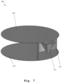
- FIG. 7 shows a further exemplary embodiment of an antenna array in the sense of the invention.
- FIG. 1 illustrates an exemplary embodiment of an antenna array 10 being attachable to a surface.
- said antenna array 10 comprises at least two antennas, which cannot be seen in this embodiment due to a housing of the array 10 , and a magnetic material and/or an alloy with ferro-magnetic properties, exemplarily equipped with reference sign 14 , for magnetically attaching at least one further antenna.
- said at least one further antenna can be further antenna array, especially at least one further directional antenna array.
- the antenna array 10 can also be a directional antenna array.
- the at least one further antenna or the further antenna array comprises a further magnetic material and/or a further alloy with ferro-magnetic properties.
- said surface can be at least part of, especially at least part of the corresponding skin of, a car, a tank, a helicopter, an airplane, or a street lamp.
- the antenna array 10 exemplarily comprises a first surface 16 a for attaching the antenna array 10 to the above-mentioned surface which is not explicitly shown.
- Said first surface 16 a can be attached to the surface, for instance, in a magnetic manner or by gluing, screwing, nailing, or the like.
- the antenna array 10 further comprises a centering unit, exemplarily a centering indentation 15 , for axially arranging the at least one further antenna or the further antenna array, respectively with respect to the antenna array 10 .
- the at least one further antenna or the further antenna array comprises a further centering unit, exemplarily a further centering peg, for axially arranging the at least one further antenna or the further antenna array, respectively, with respect to the antenna array 10 .
- the magnetic material and/or the alloy with ferro-magnetic properties is fixed to the antenna array 10 such that the at least one further antenna or the further antenna array, respectively, is located opposite to the surface in the case that the at least one further antenna or the further antenna array, respectively, is magnetically attached.
- the antenna array 10 exemplarily comprises a second surface 16 b opposite to the above-mentioned first surface 16 a .
- said second surface 16 b comprises the magnetic material and/or the alloy with ferro-magnetic properties, exemplarily equipped with reference sign 15 , or said magnetic material and/or the alloy with ferro-magnetic properties is fixed to the second surface 16 b , respectively.
- each of at least one pair out of respective normals to the surface, the first surface 16 a , and the second surface 16 b deviate not more than 10 degrees, preferably 5 degrees, more preferably 2 degrees, most preferably 0.5 degrees, from a certain direction.
- an operational frequency range of the antenna array 10 is lower than a further operational frequency range of the at least one further antenna or the further antenna array, respectively.
- the antenna array 10 can comprise or be a directional antenna array exemplarily with an operational frequency range of 0.6 GHz to 18 GHz.
- the magnetic material and/or the alloy with ferro-magnetic properties exemplarily equipped with reference sign 15 , is of annular shape.
- the alloy with ferro-magnetic properties is a ferro-metal ring, especially a steel ring.
- the antenna array 10 comprises a hole for cable routing from the at least one further antenna. Further advantageously, said hole can be located in the center of the antenna array 10 .
- the antenna array 10 comprises a cable inset 18 especially for the at least one further antenna or the further antenna array, respectively.
- Said cable inset 18 is substantially perpendicular to at least one of the surface, the first surface 16 a , and the second surface 16 b . Furthermore, said cable inset 18 may preferably be arranged in the vicinity of the housing of the antenna array. More preferably, the cable inset 18 may be arranged such that said cable inset 18 is located as far as possible from the center of the antenna array 10 .
- substantially perpendicular is especially to be understood as an angle between 80 degrees and 100 degrees, preferably between 85 degrees and 95 degrees, more preferably between 88 degrees and 92 degrees, most preferably between 89.5 degrees and 90.5 degrees.
- the antenna array 10 comprises at least one cable, especially at least one radio frequency cable, exemplarily four radio frequency cables.
- the antenna array 10 is of a circular shape.
- a diameter of said circular shape can be between 18 cm and 26 cm, preferably between 20 cm and 24 cm, more preferably between 21 cm and 23 cm, most preferably between 21.5 cm and 22.5 cm.
- a height of the antenna array 10 can be between 6 cm and 14 cm, preferably between 8 cm and 12 cm, more preferably between 9 cm and 11 cm, most preferably between 9.5 cm and 10.5 cm.
- FIG. 2 a first exemplary embodiment of the inventive antenna system is depicted.
- Said antenna system comprises the antenna array 10 according to FIG. 1 and a further antenna, exemplarily an omnidirectional antenna 21 with a further operating frequency of 0.6 GHz to 6 GHz.
- a height of the antenna system is between 11 cm and 19 cm, preferably between 13 cm and 17 cm, more preferably between 14 cm and 16 cm, most preferably between 14.5 cm and 15.5 cm.
- the omnidirectional antenna 21 can alternatively be a Global Positioning System (GPS) antenna.
- GPS Global Positioning System
- FIG. 3 a second exemplary embodiment of the inventive antenna system is depicted.
- Said antenna system comprises the antenna array 10 according to FIG. 1 and a further antenna, exemplarily an omnidirectional antenna 22 with a further operating frequency of 4.5 GHz to 70 GHz.
- a height of the antenna system is between 11 cm and 19 cm, preferably between 13 cm and 17 cm, more preferably between 14 cm and 16 cm, most preferably between 14.5 cm and 15.5 cm.
- the omnidirectional antenna 22 can alternatively be a GPS antenna.
- FIG. 4 illustrates a third exemplary embodiment of an antenna system in accordance with the second aspect of the invention.
- Said antenna system comprises the antenna array 10 according to FIG. 1 and a further antenna, exemplarily an omnidirectional antenna 23 with a further operating frequency of 0.45 GHz to 6 GHz.
- a height of the antenna system is between 18 cm and 26 cm, preferably between 20 cm and 24 cm, more preferably between 21 cm and 23 cm, most preferably between 21.5 cm and 22.5 cm.
- the omnidirectional antenna 23 can alternatively be a GPS antenna.
- FIG. 5 a fourth exemplary embodiment of the inventive antenna system is shown.
- Said antenna system comprises the antenna array 10 according to FIG. 1 and a further antenna array, exemplarily an directional antenna array 24 with a further operating frequency of 4.5 GHz to 53 GHz.
- a height of the antenna system is between 11 cm and 19 cm, preferably between 13 cm and 17 cm, more preferably between 14 cm and 16 cm, most preferably between 14.5 cm and 15.5 cm.
- the antenna array 24 is of the same type as the antenna array 10 .
- a diameter of the antenna array 24 may be at least 20 percent, preferably at least 30 percent, more preferably at least 45 percent, most preferably at least 50 percent, smaller than the diameter of the antenna array 10 .
- the antenna array 10 the above-mentioned omnidirectional antennas 21 , 22 , 23 , and the above-mentioned directional antenna array 24 , it is noted that the antenna array 10 and at least a part of said omnidirectional antennas 21 , 22 , 23 , and said directional antenna array 24 can form an antenna kit according to the third aspect of the invention.
- FIG. 6 depicts an antenna array 10 a in the sense of the invention in more detail.
- the above-mentioned antenna array 10 can be such an antenna array 10 a.
- Said antenna array 10 a comprises a monocone feed 11 a for inputting an input signal and/or outputting an output signal, and a reflecting surface 12 a comprising a parabolic shape for transmitting the input signal as an electromagnetic output wave and/or receiving an electromagnetic input wave as the output signal.
- the parabolic shape is a two-dimensional parabolic shape. Additionally, the reflecting surface 12 a is sandwiched between two planar surfaces 16 a ′, 16 b ′, which can be seen as the above-mentioned first surface 16 a and the second surface 16 b in an analogous manner.
- the reflecting surface 12 and said two planar surfaces 16 a ′, 16 b ′ especially form a cavity.
- the above-mentioned monocone feed 11 a is located inside said cavity.
- the antenna array 10 a further comprises at least one further monocone feed, exemplarily three further monocone feeds 11 b , 11 c , 11 d for inputting the input signal and/or outputting the output signal and/or for inputting a further input signal and/or outputting a further output signal, and at least one further reflecting surface, exemplarily three further reflecting surfaces 12 b , 12 c , 12 d , each comprising a further parabolic shape for transmitting the input signal as the electromagnetic output wave and/or receiving the electromagnetic input wave as the output signal and/or for transmitting the further input signal as a further electromagnetic output wave and/or receiving a further electromagnetic input wave as the further output signal.
- at least one further monocone feed exemplarily three further monocone feeds 11 b , 11 c , 11 d for inputting the input signal and/or outputting the output signal and/or for inputting a further input signal and/or outputting a further output signal
- at least one further reflecting surface exemplarily three further reflecting
- the monocone feed 11 a , the reflecting surface 12 a , the at least one further monocone feed, exemplarily the three further monocone feeds 11 b , 11 c , 11 d , and the at least one further reflecting surface, exemplarily the three further reflecting surfaces 12 b , 12 c , 12 d , are arranged to form a directional array, especially a switched directional array.
- the monocone feed 11 a , the reflecting surface 12 a , the at least one further monocone feed, exemplarily the three further monocone feeds 11 b , 11 c , 11 d , and the at least one further reflecting surface, exemplarily the three further reflecting surfaces 12 b , 12 c , 12 d , are arranged in a circular manner.
- planar surfaces 16 a ′, 16 b ′ are of circular shape and/or of the same size.
- the monocone feed 11 a and the three further monocone feeds 11 b , 11 c , 11 d substantially form the corners of an imaginary square.
- an angle between two neighboring ones of said monocone feeds 11 a , 11 b , 11 c , 11 d is between 80 degrees and 100 degrees, preferably between 85 degrees and 95 degrees, more preferably between 88 degrees and 92 degrees, most preferably between 89.5 degrees and 90.5 degrees.
- the antenna array 10 a of FIG. 6 further comprises at least one object, preferably at least one metallic object, more preferably at least one grounded metallic object, arranged in the vicinity of the reflecting surface 12 a or the further reflecting surfaces 12 b , 12 c , 12 d , respectively, especially for directing the electromagnetic output wave and/or the electromagnetic input wave or the further electromagnetic output wave and/or the further electromagnetic input wave, respectively.
- said vicinity may preferably refer to the corresponding volume of the above-mentioned cavity.
- the number of monocone feeds such as the above-mentioned monocone feeds 11 a , 11 b , 11 c , 11 d of FIG. 6 , or reflecting surfaces, such as the above-mentioned reflecting surfaces 12 a , 12 b , 12 c , 12 d of said FIG. 6 , respectively, can be varied.
- the further monocone feeds 11 b , 11 c , 11 d , and the further reflecting surfaces 12 b , 12 c , 12 d can be omitted.
Landscapes
- Engineering & Computer Science (AREA)
- Remote Sensing (AREA)
- Physics & Mathematics (AREA)
- Astronomy & Astrophysics (AREA)
- Aviation & Aerospace Engineering (AREA)
- General Physics & Mathematics (AREA)
- Details Of Aerials (AREA)
- Variable-Direction Aerials And Aerial Arrays (AREA)
Abstract
Description
Claims (20)
Priority Applications (2)
| Application Number | Priority Date | Filing Date | Title |
|---|---|---|---|
| US18/048,363 US12316029B2 (en) | 2022-10-20 | 2022-10-20 | Antenna array, antenna system and antenna kit, each being attachable to a surface |
| DE102023124098.6A DE102023124098A1 (en) | 2022-10-20 | 2023-09-07 | ANTENNA GROUP, ANTENNA SYSTEM AND ANTENNA SET, EACH OF WHICH CAN BE MOUNTED TO A SURFACE |
Applications Claiming Priority (1)
| Application Number | Priority Date | Filing Date | Title |
|---|---|---|---|
| US18/048,363 US12316029B2 (en) | 2022-10-20 | 2022-10-20 | Antenna array, antenna system and antenna kit, each being attachable to a surface |
Publications (3)
| Publication Number | Publication Date |
|---|---|
| US20240136716A1 US20240136716A1 (en) | 2024-04-25 |
| US20240235028A9 US20240235028A9 (en) | 2024-07-11 |
| US12316029B2 true US12316029B2 (en) | 2025-05-27 |
Family
ID=90573029
Family Applications (1)
| Application Number | Title | Priority Date | Filing Date |
|---|---|---|---|
| US18/048,363 Active 2043-05-18 US12316029B2 (en) | 2022-10-20 | 2022-10-20 | Antenna array, antenna system and antenna kit, each being attachable to a surface |
Country Status (2)
| Country | Link |
|---|---|
| US (1) | US12316029B2 (en) |
| DE (1) | DE102023124098A1 (en) |
Citations (5)
| Publication number | Priority date | Publication date | Assignee | Title |
|---|---|---|---|---|
| US20130330511A1 (en) * | 2012-06-08 | 2013-12-12 | Fred Sharifi | Gigahertz electromagnetic absorption in a material with textured surface |
| US20130341409A1 (en) * | 2012-06-21 | 2013-12-26 | Wistron Neweb Corporation | Multi-Function Radio-Frequency Device, Computer System and Method of Operating Multi-Function Radio-Frequency Device |
| US20160043472A1 (en) * | 2014-04-28 | 2016-02-11 | Tyco Electronics Corporation | Monocone antenna |
| US20200235473A1 (en) * | 2017-10-04 | 2020-07-23 | Tdf | Antenna with partially saturated dispersive ferromagnetic substrate |
| US20220336946A1 (en) * | 2019-09-05 | 2022-10-20 | Lg Electronics Inc. | Electronic device having antenna |
-
2022
- 2022-10-20 US US18/048,363 patent/US12316029B2/en active Active
-
2023
- 2023-09-07 DE DE102023124098.6A patent/DE102023124098A1/en active Pending
Patent Citations (5)
| Publication number | Priority date | Publication date | Assignee | Title |
|---|---|---|---|---|
| US20130330511A1 (en) * | 2012-06-08 | 2013-12-12 | Fred Sharifi | Gigahertz electromagnetic absorption in a material with textured surface |
| US20130341409A1 (en) * | 2012-06-21 | 2013-12-26 | Wistron Neweb Corporation | Multi-Function Radio-Frequency Device, Computer System and Method of Operating Multi-Function Radio-Frequency Device |
| US20160043472A1 (en) * | 2014-04-28 | 2016-02-11 | Tyco Electronics Corporation | Monocone antenna |
| US20200235473A1 (en) * | 2017-10-04 | 2020-07-23 | Tdf | Antenna with partially saturated dispersive ferromagnetic substrate |
| US20220336946A1 (en) * | 2019-09-05 | 2022-10-20 | Lg Electronics Inc. | Electronic device having antenna |
Also Published As
| Publication number | Publication date |
|---|---|
| DE102023124098A1 (en) | 2024-04-25 |
| US20240136716A1 (en) | 2024-04-25 |
| US20240235028A9 (en) | 2024-07-11 |
Similar Documents
| Publication | Publication Date | Title |
|---|---|---|
| US7420525B2 (en) | Multi-beam antenna with shared dielectric lens | |
| US9812784B2 (en) | Planar horn array antenna | |
| JPWO2017090401A1 (en) | Luneberg lens antenna device | |
| US9614292B2 (en) | Circularly polarized antenna | |
| CN107925151A (en) | Wireless transceivers and base stations | |
| US11575202B2 (en) | Monopole antenna assembly with directive-reflective control | |
| Zandamela et al. | Angle of arrival estimation via small IoT devices: Miniaturized arrays vs. MIMO antennas | |
| US9876546B2 (en) | Digital beam-forming network having a reduced complexity and array antenna comprising the same | |
| US12316029B2 (en) | Antenna array, antenna system and antenna kit, each being attachable to a surface | |
| US11063348B2 (en) | Radome and pattern forming method | |
| CN111786073B (en) | Combined antenna | |
| US2217321A (en) | Beam antenna | |
| US20240136733A1 (en) | Antenna and antenna system | |
| US10581152B2 (en) | Biaxial antenna comprising a first fixed part, a second rotary part and a rotary joint | |
| CN102570052B (en) | The compact systems of multi-beam antenna | |
| US11081797B2 (en) | Array antenna apparatus using superstrates and method of tuning array antenna by using superstrates | |
| US10483611B2 (en) | Waveguide/transmission line converter configured to feed a plurality of antenna elements in an antenna device | |
| US8664807B2 (en) | Planar tri-mode cavity | |
| RU2343603C2 (en) | Method of exciting and tuning cophased antenna array of rhomb shaped elements and antenna-feeder device to this end | |
| KR20200055646A (en) | Mimo antenna array with wide field of view | |
| KR102411588B1 (en) | Phased array antenna | |
| RU2486643C1 (en) | Antenna array | |
| JP7007024B2 (en) | Antenna device | |
| KR102393387B1 (en) | Flat tracking antenna | |
| EP3531509A1 (en) | Antenna device |
Legal Events
| Date | Code | Title | Description |
|---|---|---|---|
| FEPP | Fee payment procedure |
Free format text: ENTITY STATUS SET TO UNDISCOUNTED (ORIGINAL EVENT CODE: BIG.); ENTITY STATUS OF PATENT OWNER: LARGE ENTITY |
|
| STPP | Information on status: patent application and granting procedure in general |
Free format text: DOCKETED NEW CASE - READY FOR EXAMINATION |
|
| AS | Assignment |
Owner name: ROHDE & SCHWARZ GMBH & CO. KG, GERMANY Free format text: ASSIGNMENT OF ASSIGNORS INTEREST;ASSIGNORS:ROWELL, CORBETT;HAUSL, CHRISTOPH;SIGNING DATES FROM 20221028 TO 20230119;REEL/FRAME:062651/0764 |
|
| STPP | Information on status: patent application and granting procedure in general |
Free format text: NON FINAL ACTION MAILED |
|
| STPP | Information on status: patent application and granting procedure in general |
Free format text: RESPONSE TO NON-FINAL OFFICE ACTION ENTERED AND FORWARDED TO EXAMINER |
|
| STPP | Information on status: patent application and granting procedure in general |
Free format text: FINAL REJECTION MAILED |
|
| STPP | Information on status: patent application and granting procedure in general |
Free format text: RESPONSE AFTER FINAL ACTION FORWARDED TO EXAMINER |
|
| STPP | Information on status: patent application and granting procedure in general |
Free format text: ADVISORY ACTION MAILED |
|
| STPP | Information on status: patent application and granting procedure in general |
Free format text: DOCKETED NEW CASE - READY FOR EXAMINATION |
|
| STPP | Information on status: patent application and granting procedure in general |
Free format text: NON FINAL ACTION MAILED |
|
| STPP | Information on status: patent application and granting procedure in general |
Free format text: RESPONSE TO NON-FINAL OFFICE ACTION ENTERED AND FORWARDED TO EXAMINER |
|
| STCF | Information on status: patent grant |
Free format text: PATENTED CASE |