US12315219B2 - Information processing device, determination method, and non-transitory recording medium - Google Patents
Information processing device, determination method, and non-transitory recording medium Download PDFInfo
- Publication number
- US12315219B2 US12315219B2 US17/547,518 US202117547518A US12315219B2 US 12315219 B2 US12315219 B2 US 12315219B2 US 202117547518 A US202117547518 A US 202117547518A US 12315219 B2 US12315219 B2 US 12315219B2
- Authority
- US
- United States
- Prior art keywords
- difference
- image
- total area
- area difference
- value
- Prior art date
- Legal status (The legal status is an assumption and is not a legal conclusion. Google has not performed a legal analysis and makes no representation as to the accuracy of the status listed.)
- Active, expires
Links
Images


Classifications
-
- G—PHYSICS
- G06—COMPUTING OR CALCULATING; COUNTING
- G06V—IMAGE OR VIDEO RECOGNITION OR UNDERSTANDING
- G06V10/00—Arrangements for image or video recognition or understanding
- G06V10/70—Arrangements for image or video recognition or understanding using pattern recognition or machine learning
- G06V10/74—Image or video pattern matching; Proximity measures in feature spaces
- G06V10/761—Proximity, similarity or dissimilarity measures
-
- G—PHYSICS
- G06—COMPUTING OR CALCULATING; COUNTING
- G06V—IMAGE OR VIDEO RECOGNITION OR UNDERSTANDING
- G06V10/00—Arrangements for image or video recognition or understanding
- G06V10/40—Extraction of image or video features
- G06V10/56—Extraction of image or video features relating to colour
Definitions
- Embodiments of the present disclosure relate to an information processing device, a determination method, and a non-transitory recording medium.
- Whether two images are the same with each other or not may be desired to be determined. For example, in a field such as commercial printing in which a high-quality printed matter is desired to be obtained, a user may evaluate regarding whether a printed matter having the same image quality is obtainable after a printer driver is changed due to version upgrade. In addition, in a case of compressing an image, whether the image, Which is before compression and an image obtained by being compressed and having a deteriorated image quality due to the compression are acceptable to be regarded as the same images may be desired to be determined.
- Methods used in such known techniques include acquiring a quality deterioration index value for an input transcoded video and at least one of a bit rate value of the input transcoded video and a bit rate value of a video that is not transcoded, and estimating the quality related to user experience of the transcoded video based on the acquired values.
- An embodiment of the present disclosure includes an information processing device including circuitry to generate difference information related to a difference between a first image and a second image.
- the difference information has a plurality of areas.
- the circuitry further obtains a total value of differences in each of the plurality of areas as one of a plurality of total area difference amounts and determines whether the first image is same as the second image based on each of the plurality of total area difference amounts.
- An embodiment of the present disclosure includes a determination method including generating difference information related to a difference between a first image and a second image.
- the difference information has a plurality of areas.
- the determination method further includes obtaining a total value of differences in each of the plurality of areas as one of a plurality of total area difference amounts and determining whether the first image is same as the second image based on each of the plurality of total area difference amounts.
- An embodiment of the present disclosure includes a non transitory recording medium storing a plurality of instructions which, when executed by one or more processors, causes the processors to perform a method including, generating difference information related to a difference between a first image and a second image.
- the difference information has a plurality of areas.
- the method further includes obtaining a total value of differences in each of the plurality of areas as one of a plurality of total area difference amounts and determining whether the first image is same as the second image based on each of the plurality of total area difference amounts.
- FIG. 1 A to FIG. 1 F are diagrams illustrating two pairs of images to be compared and difference between two images in each pair, according to an exemplary embodiment of the present disclosure
- FIG. 2 A and FIG. 2 B are diagrams illustrating examples of configurations of an information processing device and an information processing system each of which performs a sameness determination, according to the exemplary embodiment of the present disclosure
- FIG. 3 is a block diagram illustrating an example of a hardware configuration of the information processing device or a server according to the exemplary embodiment of the present disclosure
- FIG. 4 is a block diagram illustrating an example of a functional configuration of the information processing device according to the exemplary embodiment of the present disclosure
- FIG. 5 is a diagram illustrating a method of generating difference information related to CMYK images by a difference information generation unit according to the exemplary embodiment of the present disclosure
- FIG. 6 A and FIG. 6 B are diagrams illustrating a method of detecting differences that are continuously arranged to have a size equal to or larger than a size that is perceptible with human eyes, according to the exemplary embodiment of the present disclosure
- FIG. 7 is a diagram illustrating a method of detecting a set of differences that occupies, in a certain area, a ratio equal to or greater than a ratio that is perceptible with human eyes, according to the exemplary embodiment of the present disclosure
- FIG. 8 A and FIG. 8 B are diagrams illustrating a method of generating difference information, according to the exemplary embodiment of the present disclosure
- FIG. 9 A is a diagram illustrating difference information indicating a difference between a reference image and a comparison image of FIG. 8 A and FIG. 8 B , according to the exemplary embodiment of the present disclosure
- FIG. 9 B is an enlarged view of a part of the difference information of FIG. 9 A , according to the exemplary embodiment of the present disclosure.
- FIG. 9 C is a diagram illustrating an example of an arrangement pattern, according to the exemplary embodiment of the present disclosure.
- FIG. 10 is a diagram illustrating a method of detecting an arrangement pattern from an arrangement of differences, according to the exemplary embodiment of the present disclosure
- FIG. 11 A and FIG. 11 B are diagrams illustrating two images between which no arrangement of differences is detected according to the exemplary embodiment of the present disclosure
- FIG. 11 C is a diagram illustrating difference information related to the two images illustrated in FIG. 11 A and FIG. 11 B , according to the exemplary embodiment of the present disclosure
- FIG. 12 A and FIG. 12 B are diagrams illustrating two images between which an arrangement of differences is detected, according to the exemplary embodiment of the present disclosure
- FIG. 12 C is a diagram illustrating difference information related to the two images illustrated in FIG. 12 A and FIG. 12 B , according to the exemplary embodiment of the present disclosure
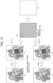
- FIG. 13 is a diagram illustrating a method of determining for sameness based on a total area difference amount, according to the exemplary embodiment of the present disclosure
- FIG. 14 is a flowchart illustrating an example of a process of determining whether two images are the same with each other based on one or more total area difference amounts, performed by the information processing device, according to the exemplary embodiment of the present disclosure
- FIG. 15 A and FIG. 15 B are diagrams illustrating a comparative example of two images to be compared with each other, according to the exemplary embodiment of the present disclosure
- FIG. 16 is a diagram illustrating a comparative example of difference information indicated by pixel level between the two images illustrated in FIG. 15 A and FIG. 15 B , according to the exemplary embodiment of the present disclosure
- FIG. 17 A and FIG. 17 B are diagrams illustrating another comparative example of two images to be compared with each other according to the exemplary embodiment of the present disclosure
- FIG. 18 is a diagram illustrating another comparative example of difference information that is an image in which a value A is reflected by using a color of red based on a total area difference amount, according to the present embodiment of the disclosure
- FIG. 19 is a diagram illustrating an example of an image to be compared with another image, according to the present embodiment of the disclosure.
- FIG. 20 is a diagram illustrating an example of an image in which a value A is reflected by using a color of red based on a total area difference amount obtained based on the two images of FIG. 17 A and FIG. 19 .
- a determination method that is performed by focusing on an arrangement of differences to determine whether two images are the same is devised in order to obtain a determination result that is closer to one obtained by determination made by humans.
- the information processing device determines that two or more images are the same with each other when a difference is within a range that is not perceptible with human eyes. Accordingly when pixels, each of which is determined to be perceptible with human eyes, of difference information related to two images are arranged in a manner that the pixels are perceptible with human eyes, it is regarded as a visible difference (“not match” (not the same)). Examples of an arrangement of differences perceptible with human eyes include the following:
- the sameness determination method performed by focusing on an arrangement of differences may obtain a determination result, which indicates whether two images are the same, close to one obtained by determination made by humans, in a case that there is a difference in shape between the two images.
- the sameness determination method performed by focusing on an arrangement of differences may obtain a determination result, which indicates whether two images are the same, different from one obtained by determination made by humans, in a case that there is a difference in hues, or color tone. That is, even when there is no difference perceptible with human eyes regarding an arrangement of differences between the two images, whether the difference between the two images is perceptible with human eyes or not changes depending on content of the images. This means that a determination result same as the one determined by humans may not be obtained by merely focusing on such an arrangement of differences.
- FIG. 1 A to FIG. 1 F are diagrams illustrating two pairs of images to be compared and difference between two images in each pair, according to an embodiment of the present disclosure.
- the two pairs are a first pair and a second pair, and content of image of the first pair is different from that of the second pair
- FIG. 1 A and FIG. 1 B are the first pair, and an image A of FIG. 1 A and an image B of FIG. 1 B are to be compared.
- FIG. 1 D and FIG. 1 E are the second pair, and an image D of FIG. 1 D and an image E of FIG. 1 E are to be compared.
- FIG. 1 C is a diagram illustrating difference C obtained by comparing the image A and the image B in the first pair.
- FIG. 1 F is a diagram illustrating difference F obtained by comparing the image D and the image E in the second pair.
- an information processing device determines whether the difference is perceptible with human eyes by comparing a total difference amount in the area (hereinafter, referred to as a total area difference amount) in difference information with a threshold value. More specifically, the total area difference amount is calculated, or obtained, tor each of a plurality of areas corresponding to the difference information, and each of a plurality of total area difference amounts total area difference amount is compared with the threshold value for the determination. That is, a determination result indicating whether the two images are the same or not is obtained by determining difference in shape by using an arrangement of differences and determining difference in hues, or color tone, by using the total area difference amount. The determination result obtained by doing so is to be closer to the one obtained by determination made by humans.
- a term of “same” means being identical, or matching, and even when there is a difference, a degree or level of the difference is not perceptible with human eyes.
- a term of “different” means being not identical, and that there is a difference that is perceptible with human eyes. “Same” may be referred to as “extremely similar,” and “different” may be referred to as “not similar nor the same.”
- FIG. 2 A and FIG. 2 B are diagrams illustrating examples of configurations of an information processing device 10 and an information processing system 100 each of which performs the sameness determination, according to an exemplary embodiment.
- the information processing device 10 performs the sameness determination, according to the exemplary embodiment.
- a server 30 performs the sameness determination, according to the exemplary embodiment.
- the information processing device 10 acquires two images stored in a storage unit, performs the sameness determination, and outputs a determination result to be displayed on a display.
- the determination result may be transmitted by e-mail or stored in the storage unit.
- the determination result may be stored in the cloud.
- the information processing device 10 may be any device on which software is operable. Examples of the information processing device 10 include, for example, a personal computer (PC), a tablet terminal, a Personal Digital Assistant (PDA), and a smartphone.
- PC personal computer
- PDA Personal Digital Assistant
- a server is a device that mainly performs information processing on a network and responds to a request received via the network with a processing result.
- the information processing device 10 transmits two or more images to the server 30 .
- the server 30 determines in relation to the sameness between the two or more images and transmits a determination result to the information processing device 10 .
- the determination result may be transmitted by e-mail or stored in the cloud.
- the server 30 in the configuration illustrated in FIG. 2 B is used as a so-called web server that generates screen information of a portal screen to receive image data and provides the screen information to the information processing device 10 .
- the screen information is described with, such as for example.
- Hypertext Markup Language HTML
- XML Extensible Markup Language
- CSS Cascading Style Sheet
- the information processing device 10 on which a web browser is operating receives the screen information and displays a web page, accordingly.
- the web page has an interface for registering two or more images, which are stored in, or held by, the information processing device 10 , and the two or more images are registered according to a user operation performed via the web page and then transmitted to the server 30 .
- the web page may be provided by using a web application.
- the “web application” is defined as software or a mechanism of software that is implemented by cooperation between a program executed on a browser and written in a programming language such as JAVASCRIPT (Registered Trademark) and a program provided by a web server.
- the web application allows information processing devices to dynamically change web pages.
- FIG. 3 is a block diagram illustrating an example of a hardware configuration of the information processing device 10 or the server 30 according to the exemplary embodiment of the disclosure.
- the information processing device 10 is used as an example to describe the hardware configuration.
- the information processing device 10 is implemented by a computer and includes a central processing unit (CPU) 501 , a read only memory (ROM) 502 , a random access memory (RAM) 503 , a hard disk (HD) 504 , a hard disk drive (HDD) controller 505 , a display 506 , an external device connection interface (I/F) 508 , a network I/F 509 , a bus line 510 , a keyboard 511 , a pointing device 512 , a digital versatile disk-rewritable (DVD-RW) drive 514 , and a media I/F 516 .
- CPU central processing unit
- ROM read only memory
- RAM random access memory
- HD hard disk
- HDD hard disk drive
- display 506 a display 506
- I/F external device connection interface
- network I/F 509 a bus line 510
- keyboard 511 a keyboard 511
- a pointing device 512 a digital versatile disk-re
- the CPU 501 performs overall control of the information processing device 10 .
- the ROM 502 stores a program such as an initial program loader (IPL) used for driving the CPU 501 .
- the RAM 503 is used as a work area for the CPU 501 .
- the HD 504 stores various data such as a program.
- the HDD controller 505 controls reading and writing of various data from and to the HD 504 under control of the CPU 501 .
- the display 506 displays various information such as a cursor, a menu, a window, a character, or an image.
- the external device connection I/F 508 is an interface for connecting to various external devices. Examples of the external devices include, but are not limited to, a universal serial bus (USB) memory and a printer.
- the network I/F 509 is an interface for performing data communication using a communication network.
- the bus line 510 is an address bus, a data bus, or the like for electrically connecting the components such as the CPU 501 illustrated in FIG. 3 each
- the keyboard 511 is an example of an input device provided with a plurality of keys for allowing a user to input characters, numerals, or various instructions.
- the pointing device 512 is an example of an input device that allows a user to select or execute a specific instruction, select a target for processing, or move a cursor being displayed.
- the DVD-RW drive 514 reads and writes various data from and to a DVD-RW 513 , which is an example of a removable storage medium.
- the DVD-RW may be an optical storage medium such as a DVD-Recordable (DVD-R).
- the media I/F 516 controls reading and writing (storing) of data from and to a storage medium 515 such as a flash memory.
- FIG. 4 is a block diagram illustrating an example of a functional configuration of the information processing device 10 according to the present embodiment of the disclosure.
- description is given assuming the functions of the information processing device 10 unless otherwise specified.
- the functions included in the server 30 may be substantially the same as those of the information processing device 10 , except for that the server 30 further includes a communication unit.
- the information processing device 10 includes an image acquisition unit 11 , a difference information generation unit 12 , a difference information output unit 13 , a difference information arrangement detection unit 14 , a first determination unit 15 , a display control unit 16 , an area difference detection unit 17 , a second determination unit 18 , and a difference amount determination unit 19 .
- Each functional unit included in the information processing device 10 is implemented by operating any of components illustrated in FIG. 3 according to an instruction from the CPU 501 according to a program expanded from the HD 504 to the RAM 503 .
- the image acquisition unit 11 acquires (reads) data corresponding to two or more images stored in the image data storage unit 21 .
- the data may be referred to as image data.
- the two or more images are mentioned above, because there may be a ease two images selected from three images are compared, for example.
- the images to be acquired may be selected by a user. Alternatively, the images may be sequentially acquired from the image data storage unit 21 .
- the difference information generation unit 12 generates difference information related to two images to be compared with each other.
- the difference information generation unit 12 generates the difference information by determining whether the same pixel (Cyan, Magenta, Yellow, and Black (CMYK)) presents or not at each of the pixel positions defined by resolution of the image.
- Cyan, Magenta, Yellow, and Black Cyan, Magenta, Yellow, and Black
- RGB images the difference information generation unit 12 calculates, for each of the pixel positions according to resolution, a value in relation to difference for each of Red, Green, and Blue (each of the Red, the Green, and the Blue, each of the RGB).
- RGB images a value range of ⁇ 255 to 255 (in a case of 8 bits per pixel) is used in relation to the difference for each of Red, Green, and Blue.
- the difference information output unit 13 stores the difference information generated by the difference information generation unit 12 in the difference information storage unit 22 .
- the difference information is two dimensional information having the same resolution (size) as the image.
- the difference information arrangement detection unit 14 detects an arrangement of differences. Although details will be described later, continuous differences (continuously arranged differences), a ratio (difference ratio) within a certain area, and a predetermined pattern (difference pattern) are detected from the difference information.
- the first determination unit 15 determines, based on an arrangement of differences detected by the difference information arrangement detection unit 14 , whether the arrangement of differences is perceptible with human eyes or not.
- the arrangement of differences that is perceptible with human eyes has a value equal to or greater than a threshold value indicating that a difference is perceptible with human eyes.
- the threshold value is determined according to whether a difference between two images is determinable to be present with the human visual perception. When there is a difference that is perceptible with human eyes, a determination result indicates that the two images are not the same with each other, and when there is no difference that is perceptible with human eyes, a determination result indicates that the two images are the same with each other.
- the first determination unit 15 determines whether a value corresponding to the continuous differences or a value corresponding to the ratio within a certain area is equal to or greater than the threshold value, which indicates that a difference is perceptible with human eyes is determined.
- the first determination unit 15 determines that the two images are not the same with each other.
- the area difference detection unit 17 calculates a total area difference amount in the difference information generated by the difference information generation unit 12 .
- the area difference detection unit 17 calculates a total area difference amount for each of a plurality of areas corresponding to the entire difference information (the entire two dimensional image) while moving one to another of the plurality of areas.
- the second determination unit 18 determines whether each total area difference amount is equal to or greater than the threshold value. When there is at least one area of which the total area difference amount is equal to or greater than the threshold value, the second determination unit 18 determines that the two images are not the same with each other.
- the difference amount determination unit 19 determines how much the total area difference amount exceeds the threshold value. The greater the total area difference amount exceeds the threshold value, the easier the difference is noticed by humans.
- the display control unit 16 displays an arrangement of differences and a total area difference amount on the display 506 in an emphasized manner.
- FIG. 5 is a diagram illustrating a method of generating the difference information related to CMYK images by the difference information generation unit 12 , according to the present embodiment of the disclosure.
- the difference information generation unit 12 determines whether there is a difference between the images for each of the pixel positions that are determined according to resolution of the image (for example, in a case of an image having the resolution of 1980 ⁇ 1280, the vertical is equally divided into 1980 and the horizontal is equally divided into 1280).
- intersection points of the mesh are the pixel positions.
- the difference information generation unit 12 sets a flag at a pixel position that has a difference.
- the difference information is represented by an image, a dot is placed at a pixel position where the flag is set. For example, the difference information generation unit 12 prepares a table having records of which the number is corresponding to the number of pixel positions and records “presence or absence of flag.”
- the difference information generation unit 12 may use a value corresponding to a degree or a level of the difference as the difference information. For example, it is assumed that there are the following differences in pixel positions between one image data and the other image data.
- the difference information generation unit 12 may combine one or more pixels with another one or more pixels in each image to calculate a feature amount, and then compare the feature amounts. For example, pixels around a pixel position are weighted by Gaussian smoothing or the like, and a difference between weighted values is recorded in the table. Alternatively, when there is a difference larger than the threshold value, the presence of difference (flag) is recorded in the table.
- the difference information arrangement detection unit 14 scans the pixel positions in a sequential order and detects continuous differences.
- FIG. 6 A and FIG. 6 B are diagrams illustrating a method of detecting differences that are continuously arranged to have a size equal to or larger than a size that is perceptible with human eyes, according to the present embodiment of the disclosure.
- the difference information arrangement detection unit 14 scans the pixel positions in the horizontal direction. Accordingly, when there is a difference equal to or larger than a difference 130 that has a size that is perceptible with human eyes, in the horizontal direction, the difference is detectable.
- the difference information arrangement detection unit 14 scans pixel positions in the vertical direction. Accordingly, when there is a difference (a set of continuous differences, continuous differences) equal to or larger than a difference 131 that has a size that is perceptible with human eyes, in the horizontal direction, the difference is detectable.
- the arrangement of differences of a rectangular shape is detected by scanning in the vertical direction and in the horizontal direction, as illustrated in FIG. 6 A and FIG. 6 B , respectively.
- the difference information arrangement detection unit 14 detects a length of differences continuously arranged (a length of continuous differences) in each of the vertical direction and horizontal direction. Note that the difference information arrangement detection unit 14 may also scan in an oblique direction.
- the first determination unit 15 compares the length of differences continuously arranged with a predetermined length (threshold value), and when the length of differences continuously arranged is longer than the predetermined length, records at the pixel positions corresponding to the differences continuously arranged to indicate that the length is longer than the predetermined length.
- the difference information arrangement detection unit 14 prepares a table that has records of which the number is corresponding to the number of pixel positions and records “presence of difference” for each of the pixel positions corresponding to the differences continuously arranged to have the length longer than the predetermined length.
- the display control unit 16 of the information processing device 10 may display the corresponding pixels in an emphasized manner, and this allows the user to notice the arrangement of differences easily.
- the predetermined length may be set to a certain value used for all images.
- the difference information arrangement detection unit 14 sequentially moves a window that encloses pixel positions on the difference information, and determines whether there is a set of differences, which are pixels (pixel positions) each of which is determined as a difference, occupying a ratio greater than the ratio that is perceptible with human eyes within the window or not.
- a size of the window corresponds to the certain area.
- FIG. 7 is a diagram illustrating a method of detecting a set of differences that occupies a ratio greater than the ratio that is perceptible with human eyes in a certain area, according to the present embodiment of the disclosure.
- a window 140 having 4 ⁇ 4 pixels is illustrated, but the size of the window 140 is an example and not the limiting.
- the window 140 moves in a manner that a pixel position at the center of the window 140 starts from at a corner of the upper left and moves to the right end pixel by pixel. Then, after being at the right end, the window 140 moves down by one pixel row, and then returns to the left in the same manner, for example. Such the above-described movement is repeated until the pixel position at the center comes to the lower right corner.
- the difference information arrangement detection unit 14 counts the number of pixel positions each of which is determined as a difference within the window. In FIG. 7 , for the sake of explanatory convenience, nine pixel positions are illustrated as being determined as the differences.
- the first determination unit 15 determines whether a condition of “9/25>a predetermined ratio” is satisfied or not and when the condition is satisfied, the first determination unit 15 records, in a table, which has records of which the number is corresponding to the number of pixel positions, “presence of difference” for each of the pixel positions corresponding to the nine pixel positions in the window. Accordingly, the display control unit 16 of the information processing device 19 may display the corresponding pixels in an emphasized manner, and this allows the user to notice the arrangement of differences easily.
- the predetermined ratio may be set to a certain value used for all images.
- the difference information arrangement detection unit 14 holds a specified arrangement pattern.
- the difference information arrangement detection unit 14 performs pattern matching on the difference information using an arrangement pattern, and determines whether there is an arrangement of differences that matches the arrangement pattern.
- FIG. 8 A and FIG. 8 B are diagrams illustrating a method of generating difference information, according to the present embodiment of the disclosure.
- FIG. 8 A is a diagram illustrating an example of a first image for comparison (may be referred to as a reference image)
- FIG. 9 B is a diagram illustrating an example of a second image for comparison (may be referred to as a comparison image).
- the reference image and the comparison image illustrated are clearly different from each other, for the sake of explanatory convenience, however, there is a case where a difference between a reference image and a comparison image is not perceptible with human eyes.
- FIG. 9 A is a diagram illustrating difference information indicating a difference between the reference image and the comparison image of FIG. 8 A and FIG. 8 B , according to the present embodiment of the disclosure.
- FIG. 9 B is an enlarged view of a part of the difference information of FIG. 9 A , according to the present embodiment of the disclosure.
- FIG. 9 C is a diagram illustrating an arrangement pattern 150 , according to the present embodiment of the disclosure.
- the arrangement pattern 150 is generated in advance as a difference pattern that is easily perceived by human eyes (perceptible with human eyes).
- the arrangement pattern 150 illustrated in FIG. 9 C is an example.
- the arrangement pattern is a band shape, a circular shape, or a geometrical pattern, for example.
- the difference information arrangement detection unit 14 determines that there is a difference between the two images, and the difference between the two images is detected as being perceived by human.
- the difference information arrangement detection unit 14 determines that there is a difference between the two images based on the arrangement pattern 150 , the difference between the two images is detected as being perceived by human.
- FIG. 10 is a diagram illustrating a method of detecting an arrangement pattern from an arrangement of differences 160 , according to the present embodiment of the present disclosure.
- the arrangement of differences 160 has the same pattern as the arrangement pattern 150 .
- the difference information arrangement detection unit 14 moves the arrangement pattern 150 starting from at a corner of the upper left on difference information 151 and moves to the right end pixel by pixel. Then, after being at the rigid end, the arrangement pattern 150 moves down by one pixel raw, and then returns to the left in the same manner, for example.
- the difference information arrangement detection unit 14 repeats such the above-described movement until the arrangement pattern 150 reaches the lower right corner.
- the difference information arrangement detection unit 14 determines whether “presence of difference” is recorded with respect to the difference information at the same position as each of the pixels of the arrangement pattern 150 , and when the “presence of difference” is recorded at each position of all pixels corresponding to the arrangement pattern 150 , the arrangement pattern 150 is determined as being detected from the difference information 151 . Alternatively, when the “presence of difference” is recorded at each position of a certain number or more (a certain percentage or more) of the pixels corresponding to the arrangement pattern 150 , the arrangement pattern 150 is determined as being detected from the difference information 151 .
- FIG. 10 there is the arrangement of differences 160 that matches the arrangement pattern 150 in the lower right of the difference information 151 , and the arrangement of differences 160 is to be detected by the difference information arrangement detection unit 14 .
- the difference information arrangement detection unit 14 records, in a table, which has records of which the number is corresponding to the number of pixel positions, the “presence of difference” for each of the pixel positions included in an arrangement pattern that matches the arrangement pattern 150 . Accordingly, the display control unit 16 of the information processing device 10 may display the corresponding pixels in an emphasized manner, and this allows the user to notice the arrangement of differences easily.
- FIG. 11 A and FIG. 11 B are diagrams illustrating two images between which no arrangement of differences is detected
- FIG. 11 C is a diagram illustrating difference information related to the two images illustrated in FIG. 11 A and FIG. 11 B , according to the present embodiment.
- FIG. 11 A is a diagram illustrating an example of a reference image
- FIG. 11 B is a diagram illustrating an example of a comparison image that is compressed by Joint Photographic Experts Group (JPEG)
- FIG. 11 C is a diagram illustrating an example of difference information, according to the present embodiment of the disclosure.
- JPEG Joint Photographic Experts Group
- CMYK image an image of Cyan, Magenta, Yellow, and Black
- the RGB images are also applicable.
- FIG. 11 A There is no difference between the two images illustrated in FIG. 11 A and FIG. 11 B when being viewed by humans (perceived by human eyes).
- the difference information illustrated in FIG. 11 C there is difference like noise as a whole.
- the noise is detected as the difference between the two images, and an information processing device according to the conventional technique determines that the two images are not the same.
- the information processing device 10 does not detect the arrangement of differences on the difference information and determines that the two images of FIG. 11 A and FIG. 11 B are the same.
- FIG. 12 A and FIG. 12 B are diagrams illustrating two images between which an arrangement of differences is detected
- FIG. 12 C is a diagram illustrating the difference information related to the two images illustrated in FIG. 12 A and FIG. 12 B , according to the present embodiment.
- FIG. 12 A is a diagram illustrating an example of a reference image
- FIG. 12 B is a diagram illustrating an example of a comparison image to which a white rectangle 170 is added
- FIG. 12 C is a diagram illustrating an example of difference information, according to the present embodiment of the disclosure.
- a CMYK image is used with respect to the images illustrated in FIG. 12 A , FIG. 12 B , and FIG. 12 C , the RGB images are also applicable.
- a difference is clearly noticed between the two images illustrated in FIG. 12 A and FIG. 12 B .
- a difference arrangement (arrangement of differences) 171 is detected at the same pixel positions as the white rectangle 170 in the comparison image.
- the difference arrangement 171 is indicated by black and white for the sake of drawing, but is highlighted in red or the like on the display 506 , and displayed in a different manner from the noise as illustrated in FIG. 11 C . Accordingly, the user determines whether there is an arrangement of differences or not easily.
- the information processing device 10 determines that the two images of FIG. 12 A and FIG. 12 are not the same.
- FIG. 13 is a diagram illustrating a method of determining for sameness based on each total area difference amount (a total amount of differences in each of the plurality of areas).
- an image (a) and an image (b) are compared with each other (examples of a first image and a second image).
- the difference information generation unit 12 performs smoothing processing on the image (a) and the image (b) illustrated in FIG. 13 .
- the difference information generation unit 12 performs the smoothing processing on a CMYK image with which dots are conspicuous.
- Gaussian smoothing for the smoothing processing, a CMYK image is converted into an RGB image.
- an image (c) and an image (d) are the RGB images generated by Gaussian smoothing. Comparing an enlarged area 201 - 1 in the image (a) illustrated in FIG. 13 and an enlarged area 201 - 2 in the image (c) illustrated in FIG. 13 , the dots are more smoothed in the image (c). Comparing an enlarged area 202 - 1 in the image (b) illustrated in FIG. 13 and an enlarged area 202 - 2 in the image (d) illustrated in FIG. 13 , the dots are more smoothed in the image (d).
- the difference information generation unit 12 generates difference information related to the image (c) and the image (d) illustrated in FIG. 13 .
- Each of the image (c) and the image (d) illustrated in FIG. 13 is an RGB image that has a range of pixel value from 0 to 255 (an example of second value range), for example.
- a pixel value of the image (d) which is an RGB image and illustrated in FIG. 13
- difference information in which a difference having a value range of ⁇ 255 to 255 (an example of first value range) for each of Red, Green, and Blue may occur for each pixel is obtained.
- the difference information generation unit 12 maps the value range of ⁇ 255 to 255 to the value range of 0 to 255 in the difference information.
- the difference information generation unit 12 performs mapping as follows, for example:
- an original difference of 0 corresponds to 127, and 127 in the mapped image indicates no difference.
- a difference file (e) illustrated in FIG. 13 indicates the difference information after the mapping.
- the difference information (e) illustrated in FIG. 13 is represented with gray in whole, and this indicates that there is no difference in arrangement between the two images. Note that, in order to fully use the 8-bit scale, the difference information generation unit 12 according to the present embodiment performs mapping in the value range of 0 to 255. In some embodiments, a value range of 0 to 127 or a value range of 0 to 511 may be used.
- the area difference detection unit 17 calculates a total value of the pixel values included in an area 210 for each of Red, Green, and Blue.
- the area difference detection unit 17 shifts, or moves, the area 210 in the right direction pixel by pixel, and at each time of movement, calculates for the total value in the same manner as described above.
- the area difference detection unit 17 shifts, or moves the area 210 downward by one pixel row, returns to the left end, and then performs scanning in the right direction.
- the area difference detection unit 17 compares the total value for each of Red, Green, and Blue with the threshold value that varies between Red, Green, and Blue, for each area 210 , and records in relation to the area 210 in which the total value being equal to or greater than the threshold value is obtained. Accordingly, coordinates of an area having a difference corresponding to the area 210 are obtained. The area difference detection unit 17 records for positions corresponding to the area 210 whose total value is equal to or greater than the threshold value for each of Red, Green, and Blue.
- the areas 210 that has the total value equal to or greater than the threshold value for Red, the areas 210 that has the total value equal to or greater than the threshold value for Green, and the areas 210 that has the total value equal to or greater than the threshold value for Blue are combined. This allows the user to specify an area that has a difference easily.
- FIG. 14 is a flowchart illustrating an example of a process of determining whether two images are the same with each other based on each total area difference amount, performed by the information processing device 10 according to the present embodiment of the disclosure.
- the process may be referred to as a sameness determination process, in the description of the present embodiment.
- the image acquisition unit 11 acquires two images to be compared from the image data storage unit 21 (Step S 1 ).
- the difference information generation unit 12 aligns the orientations of the two images (Step S 2 ). For example, assuming that a vertical size is H, and a horizontal size is W, the difference information generation unit 12 aligns the orientations of the two images so dial each ratio between the vertical and horizontal directions of corresponding images is H:W.
- the orientation of the comparison image may be changed, or the orientation of the reference image may be changed.
- the difference information generation unit 12 arranges the two images in resolution (Step S 3 ). That is, the difference information generation unit 12 arranges the two images in size. A difference information generation unit 12 reduces or enlarges the comparison image in accordance with the reference image. With the processing of steps S 2 and S 3 , an accurate comparison of the two images is to be performed.
- the difference information generation unit 12 performs the smoothing processing on the two images by Gaussian smoothing or the like (S 4 ).
- the CMYKs image are converted into the RGB images.
- An averaging filter or a median filter may be used for the smoothing processing.
- the difference information generation unit 12 calculates a difference of pixel value for each of Red, Green, and Blue (Step S 5 ).
- a value of difference is in the value range of ⁇ 255 to 255.
- the difference information generation unit 12 maps, in relation to the difference, from the value range of ⁇ 255 to 255 to the value range of 0 to 255 (Step S 6 ).
- the mapping may be conversion of a negative value to a positive value, and the value range to be mapped is not limited to the value range of 0 to 255.
- the area difference detection unit 17 calculates the total area difference amount by summing up the differences within each area while moving the plurality of areas corresponding to the difference information (Step S 7 ).
- the second determination unit 18 determines whether there is an area of which the total area difference amount for any of Red, Green, and Blue is equal to or greater than the threshold value (Step S 8 ).
- the second determination unit may use the threshold value that varies between Red, Green, and Blue. This is because the sensitivity of human visual perception differs between Red, Green, and Blue.
- the threshold value includes a first threshold value, a second threshold value, and a third threshold value corresponding to Red, Green, and Blue, respectively.
- the total area difference amount for Red an example of first total area difference amount
- whether the total area difference amount for Green an example of second total area difference amount
- whether the total area difference amount for Blue an example of third total area difference amount
- the total area difference amount as an area is determined to be equal to or greater than the threshold value, namely the corresponding area is determined to have a difference.
- the second determination unit 18 determines that the two images are not the same (Step S 9 ).
- the difference amount determination unit 19 calculates “total value/threshold value” for each of Red, Green, and Blue (example of first value) (Step S 10 ). That is, the difference amount determination unit 19 divides each of the first area difference amount, the second area difference amount, and the third area difference amount by the threshold value or the corresponding one of the first threshold value, the second threshold value, and the third threshold value to obtain the first values. A result obtained by the calculation is referred to as “values A.” The larger the values A are, the larger the difference becomes.
- the difference amount determination unit 19 performs weighting processing on each of the values A each of which is corresponding one of Red, Green, and Blue to obtain weighted values A (example of second values) and sums up the weighted values A in the area to obtain a difference value indicating a degree or level of the difference (Step S 11 ).
- the weighting processing is performed taking into account the sensitivity of the human visual perception with respect to each of Red, Green, and Blue, namely the weighting processing may be performed according to each of Red, Green, and Blue.
- the difference amount determination unit 19 may use as a difference value one of the values A that has the largest value (maximum value) among the values A.
- the difference amount determination unit 19 may use as a difference value one of the values A corresponding to one of Red, Green, and Blue (for example, Green) by taking into account the sensitivity of human visual perception.
- the display control unit 16 generates an image by reflecting the values A, for example, by setting intensity of color of red (intensity of red) according to the values A (Step S 12 ).
- the display control unit 16 converts the values A into a red-based color between (0, 0, 0) to (255, 0, 0) by using, for example, a predetermined table. Due to this, the larger the values A are, a red color converted becomes deeper, or darker, namely has higher intensity. Accordingly, the user recognizes, or perceives, a difference in a manner that a degree or a level of the difference is larger in an area indicated by deeper red, or darker red, namely by red color having higher intensity.
- FIG. 15 A , FIG. 15 B , and FIG. 16 are diagram illustrating a comparative example of two images and difference information based on a total area difference amount, according to the present embodiment of the disclosure.
- FIG. 15 A and FIG. 15 B are diagrams illustrating two images to be compared with each other. Although these images are not strictly the same, a determination result obtained by the human visual perception indicates that there is no difference between the two images.
- FIG. 16 is a diagram illustrating an example of difference information indicated by pixel level between the two images illustrated in FIG. 15 A and FIG. 15 B .
- the information processing device 10 outputs a determination result of the sameness determination similar to a determination result made by a human.
- FIG. 17 A , FIG. 17 B , and FIG. 18 are diagrams illustrating another comparative example of two images and difference information based on a total area difference amount, according to the present embodiment of the disclosure
- FIG. 17 A and FIG. 17 B are diagrams illustrating two images to be compared with each other. With the human visual perception, it is determined that the two images are different from each other.
- FIG. 18 is an image in which the value A is reflected by using red color based on the total area difference amount. As illustrated in FIG. 18 , since an area having a difference is colored in red based on the total area difference amount and this allows the user to determine where the difference is easily.
- FIG. 19 is a diagram illustrating an image, which is different from the image illustrated in FIG. 17 B and to be compared with the image illustrated in FIG. 17 A .
- a determination result made by human with respect to the comparison of the two images of FIG. 17 A and FIG. 19 indicates that a degree or a level of the difference is larger than that of the comparison of the two images of FIG. 17 A and FIG. 17 B .
- FIG. 20 is an image in which the value A is reflected by using a color of red based on the total area difference amount obtained based on the two images of FIG. 17 A and FIG. 19 . As illustrated in FIG. 20 , an area having a difference is colored in red based on the total area difference amount. The red color in FIG. 20 is generally darker than that in FIG. 18 .
- a degree or a level of a difference is indicated by intensity of red color, and thus it is not necessary for a human to visually check the original image. Accordingly, priorities are settable, in a case where there is a large number of differences between images, after the information processing device performs the sameness determination.
- an information processing device determines whether difference is perceptible with human eyes by comparing a total area difference amount in difference information to a threshold value. A determination result indicating as to whether the two images are the same or not regarding a difference in the hue or the color tone which is difficult to be detect by the arrangement of differences is obtained so that the determination result is close to a determination result obtained by human.
- a determination result may be different from a determination result made by human (human visual perception, human eyes). For example, even in a case of desiring to obtain a result indicating whether two images are perceived as the same by human or not, the images are determined not to be the same with each other due to a slight difference detected by image processing.
- an information processing device a determination method, a program or the like that determines whether two images are the same or not and obtains a determination result that is close to a determination result obtained by human visual perception is provided.
- the functional configuration illustrated in FIG. 4 is divided according to main functions in order to facilitate understanding of processing performed by the information processing device 10 .
- Each processing unit or each specific name of the processing unit is not to limit a scope of the present disclosure.
- the processing of the information processing device 10 may be divided into more processing units according to the details of processing. Also, one processing unit may be divided so as to include more processes.
- processing circuit or circuitry includes a programmed processor to execute each function by software, such as a processor implemented by an electronic circuit, and devices, such as an Application Specific Integrated Circuit (ASIC), a Digital Signal Processors (DSP), a Field Programmable Gate Array (FPGA), and conventional circuit modules arranged to perform the recited functions.
- ASIC Application Specific Integrated Circuit
- DSP Digital Signal Processors
- FPGA Field Programmable Gate Array
Landscapes
- Engineering & Computer Science (AREA)
- Theoretical Computer Science (AREA)
- Computer Vision & Pattern Recognition (AREA)
- Multimedia (AREA)
- General Physics & Mathematics (AREA)
- Physics & Mathematics (AREA)
- Computing Systems (AREA)
- General Health & Medical Sciences (AREA)
- Medical Informatics (AREA)
- Software Systems (AREA)
- Evolutionary Computation (AREA)
- Databases & Information Systems (AREA)
- Artificial Intelligence (AREA)
- Health & Medical Sciences (AREA)
- Image Analysis (AREA)
- Image Processing (AREA)
Abstract
Description
-
- (i) The pixels each of which is determined as a difference are continuously arranged to have a size equal to or larger than a size that is perceptible with human eyes.
- (ii) The pixels each of which is determined as a difference are arranged to occupy a ratio equal to or greater than a ratio that perceptible with human eyes in a certain area.
- (iii) The pixels each of which is determined as a difference are arranged in a specified arrangement pattern.
Overview of Sameness Determination:
-
- A (C: presence, K: presence)
- B (C: presence, Y: presence)
- C (C: presence, none)
- D (C: presence, M: presence)
In this case, the level of the difference is considered to be larger in an order of A<B<C<D. That is, the differenceinformation generation unit 12 sets values to be A<B<C<D (to be bigger in the order of D, C, B, and A) in the table.
-
- −255 and −254 to 0
- −253 and −252 to 1
- −1 and 0 to 127
- 1 to 128
- 2 and 3 to 129
- 254 and 255 to 255
Claims (11)
Applications Claiming Priority (2)
| Application Number | Priority Date | Filing Date | Title |
|---|---|---|---|
| JP2021020110A JP7613142B2 (en) | 2021-02-10 | 2021-02-10 | PROGRAM, INFORMATION PROCESSING APPARATUS, AND DECISION METHOD |
| JP2021-020110 | 2021-02-10 |
Publications (2)
| Publication Number | Publication Date |
|---|---|
| US20220254142A1 US20220254142A1 (en) | 2022-08-11 |
| US12315219B2 true US12315219B2 (en) | 2025-05-27 |
Family
ID=82705026
Family Applications (1)
| Application Number | Title | Priority Date | Filing Date |
|---|---|---|---|
| US17/547,518 Active 2043-07-10 US12315219B2 (en) | 2021-02-10 | 2021-12-10 | Information processing device, determination method, and non-transitory recording medium |
Country Status (2)
| Country | Link |
|---|---|
| US (1) | US12315219B2 (en) |
| JP (1) | JP7613142B2 (en) |
Citations (10)
| Publication number | Priority date | Publication date | Assignee | Title |
|---|---|---|---|---|
| JP2000066658A (en) | 1998-08-19 | 2000-03-03 | Fuji Xerox Co Ltd | Image processor and recording medium |
| JP2010045676A (en) | 2008-08-15 | 2010-02-25 | Nippon Telegr & Teleph Corp <Ntt> | Color conversion information generating apparatus, color conversion information generating method and program |
| JP2013186562A (en) | 2012-03-06 | 2013-09-19 | Ricoh Co Ltd | Image detection apparatus and method |
| JP2014071046A (en) | 2012-09-28 | 2014-04-21 | Fujifilm Corp | Image evaluating device, image evaluating method, and program |
| JP2014154027A (en) | 2013-02-12 | 2014-08-25 | Ricoh Co Ltd | Image inspection apparatus, image inspection system, and image inspection method |
| US20140314281A1 (en) * | 2012-09-14 | 2014-10-23 | Ricoh Company, Limited | Image inspection apparatus, image inspection system and image inspection method |
| JP2016046685A (en) | 2014-08-22 | 2016-04-04 | 日本電信電話株式会社 | Device, method and program for estimating user sensory quality of video |
| JP2021026614A (en) | 2019-08-07 | 2021-02-22 | 株式会社リコー | Program, information processing device and determination method |
| JP2021103476A (en) | 2019-12-25 | 2021-07-15 | 株式会社リコー | Information processing system, information processing device, evaluation method, and program |
| US20210256289A1 (en) * | 2020-02-18 | 2021-08-19 | Ricoh Company, Ltd. | Information processing device, method of generating information, information processing system, and non-transitory recording medium |
Family Cites Families (3)
| Publication number | Priority date | Publication date | Assignee | Title |
|---|---|---|---|---|
| JP4029997B2 (en) | 2001-02-08 | 2008-01-09 | 株式会社リコー | Color conversion apparatus, color conversion method, program, and recording medium |
| JP5094615B2 (en) | 2008-07-29 | 2012-12-12 | 京セラドキュメントソリューションズ株式会社 | Image forming apparatus |
| JP6455010B2 (en) | 2014-07-31 | 2019-01-23 | 日本電気株式会社 | Information processing apparatus, information processing method, and program |
-
2021
- 2021-02-10 JP JP2021020110A patent/JP7613142B2/en active Active
- 2021-12-10 US US17/547,518 patent/US12315219B2/en active Active
Patent Citations (10)
| Publication number | Priority date | Publication date | Assignee | Title |
|---|---|---|---|---|
| JP2000066658A (en) | 1998-08-19 | 2000-03-03 | Fuji Xerox Co Ltd | Image processor and recording medium |
| JP2010045676A (en) | 2008-08-15 | 2010-02-25 | Nippon Telegr & Teleph Corp <Ntt> | Color conversion information generating apparatus, color conversion information generating method and program |
| JP2013186562A (en) | 2012-03-06 | 2013-09-19 | Ricoh Co Ltd | Image detection apparatus and method |
| US20140314281A1 (en) * | 2012-09-14 | 2014-10-23 | Ricoh Company, Limited | Image inspection apparatus, image inspection system and image inspection method |
| JP2014071046A (en) | 2012-09-28 | 2014-04-21 | Fujifilm Corp | Image evaluating device, image evaluating method, and program |
| JP2014154027A (en) | 2013-02-12 | 2014-08-25 | Ricoh Co Ltd | Image inspection apparatus, image inspection system, and image inspection method |
| JP2016046685A (en) | 2014-08-22 | 2016-04-04 | 日本電信電話株式会社 | Device, method and program for estimating user sensory quality of video |
| JP2021026614A (en) | 2019-08-07 | 2021-02-22 | 株式会社リコー | Program, information processing device and determination method |
| JP2021103476A (en) | 2019-12-25 | 2021-07-15 | 株式会社リコー | Information processing system, information processing device, evaluation method, and program |
| US20210256289A1 (en) * | 2020-02-18 | 2021-08-19 | Ricoh Company, Ltd. | Information processing device, method of generating information, information processing system, and non-transitory recording medium |
Non-Patent Citations (1)
| Title |
|---|
| Office Action dated Oct. 1, 2024 issued in corresponding Japanese Patent Application No. 2021-020110. |
Also Published As
| Publication number | Publication date |
|---|---|
| JP7613142B2 (en) | 2025-01-15 |
| US20220254142A1 (en) | 2022-08-11 |
| JP2022122703A (en) | 2022-08-23 |
Similar Documents
| Publication | Publication Date | Title |
|---|---|---|
| US11735313B2 (en) | Information processing device, method of generating information, information processing system, and non-transitory recording medium | |
| CN101331515B (en) | Gray-scale correcting method, gray-scale correcting device, gray-scale correcting program, and image device | |
| EP1453006A1 (en) | Converted digital colour image with improved colour distinction for colour-blinds | |
| US7953296B2 (en) | Image resolution conversion with error detection | |
| JP2020067959A (en) | Image processing apparatus, and control method and program thereof | |
| US10931942B2 (en) | Evaluation system and evaluation method | |
| US9338310B2 (en) | Image processing apparatus and computer-readable medium for determining pixel value of a target area and converting the pixel value to a specified value of a target image data | |
| JP5067224B2 (en) | Object detection apparatus, object detection method, object detection program, and printing apparatus | |
| US12315219B2 (en) | Information processing device, determination method, and non-transitory recording medium | |
| US10896344B2 (en) | Information processing apparatus, information processing method, and computer program | |
| US20090244570A1 (en) | Face image-output control device, method of controlling output of face image, program for controlling output of face image, and printing device | |
| US9191536B2 (en) | Processing apparatus | |
| US11467784B2 (en) | Information processing apparatus, image collating method, and program | |
| US20200280675A1 (en) | Storage Medium Storing Program, Terminal Apparatus, and Control Apparatus | |
| JP4222013B2 (en) | Image correction apparatus, character recognition method, and image correction program | |
| JP2017135433A (en) | Image processing apparatus and program | |
| EP1453008A1 (en) | Cocverted digital colour image with improved colour distinction for colour-blinds | |
| JP4595801B2 (en) | Image processing device | |
| JP2020102148A (en) | Image processing device, image processing method, and program | |
| JP2020088709A (en) | Image processing apparatus, image processing method and program | |
| US11650770B2 (en) | Image enlargement/reduction rate calculation apparatus, image enlargement/reduction rate calculation method, image enlargement/reduction rate calculation program, and recording medium storing the program | |
| US9489590B2 (en) | Color mode determination apparatus and non-transitory computer readable medium storing color mode determination program | |
| US20240146860A1 (en) | Image processing apparatus capable of preventing failure in decoding additional information embedded in print, method of controlling image processing apparatus, and storage medium | |
| JP2023153638A (en) | Program, information processing device, judgment method | |
| JP5609573B2 (en) | Driver program and printing system |
Legal Events
| Date | Code | Title | Description |
|---|---|---|---|
| FEPP | Fee payment procedure |
Free format text: ENTITY STATUS SET TO UNDISCOUNTED (ORIGINAL EVENT CODE: BIG.); ENTITY STATUS OF PATENT OWNER: LARGE ENTITY |
|
| AS | Assignment |
Owner name: RICOH COMPANY LTD., JAPAN Free format text: ASSIGNMENT OF ASSIGNORS INTEREST;ASSIGNOR:SAKAMOTO, TSUYOSHI;REEL/FRAME:058386/0994 Effective date: 20211206 |
|
| STPP | Information on status: patent application and granting procedure in general |
Free format text: DOCKETED NEW CASE - READY FOR EXAMINATION |
|
| STPP | Information on status: patent application and granting procedure in general |
Free format text: NON FINAL ACTION MAILED |
|
| STPP | Information on status: patent application and granting procedure in general |
Free format text: RESPONSE TO NON-FINAL OFFICE ACTION ENTERED AND FORWARDED TO EXAMINER |
|
| STPP | Information on status: patent application and granting procedure in general |
Free format text: FINAL REJECTION MAILED |
|
| STPP | Information on status: patent application and granting procedure in general |
Free format text: RESPONSE AFTER FINAL ACTION FORWARDED TO EXAMINER |
|
| STPP | Information on status: patent application and granting procedure in general |
Free format text: NOTICE OF ALLOWANCE MAILED -- APPLICATION RECEIVED IN OFFICE OF PUBLICATIONS |
|
| STCF | Information on status: patent grant |
Free format text: PATENTED CASE |