US12309486B2 - Transmission element imaging device and transmission element imaging method - Google Patents
Transmission element imaging device and transmission element imaging method Download PDFInfo
- Publication number
- US12309486B2 US12309486B2 US17/817,047 US202217817047A US12309486B2 US 12309486 B2 US12309486 B2 US 12309486B2 US 202217817047 A US202217817047 A US 202217817047A US 12309486 B2 US12309486 B2 US 12309486B2
- Authority
- US
- United States
- Prior art keywords
- transmission element
- camera
- image
- substrate
- reception
- Prior art date
- Legal status (The legal status is an assumption and is not a legal conclusion. Google has not performed a legal analysis and makes no representation as to the accuracy of the status listed.)
- Active, expires
Links
Images


Classifications
-
- H—ELECTRICITY
- H04—ELECTRIC COMMUNICATION TECHNIQUE
- H04N—PICTORIAL COMMUNICATION, e.g. TELEVISION
- H04N23/00—Cameras or camera modules comprising electronic image sensors; Control thereof
- H04N23/60—Control of cameras or camera modules
- H04N23/66—Remote control of cameras or camera parts, e.g. by remote control devices
-
- H—ELECTRICITY
- H04—ELECTRIC COMMUNICATION TECHNIQUE
- H04N—PICTORIAL COMMUNICATION, e.g. TELEVISION
- H04N23/00—Cameras or camera modules comprising electronic image sensors; Control thereof
- H04N23/60—Control of cameras or camera modules
- H04N23/695—Control of camera direction for changing a field of view, e.g. pan, tilt or based on tracking of objects
-
- H—ELECTRICITY
- H04—ELECTRIC COMMUNICATION TECHNIQUE
- H04N—PICTORIAL COMMUNICATION, e.g. TELEVISION
- H04N23/00—Cameras or camera modules comprising electronic image sensors; Control thereof
- H04N23/80—Camera processing pipelines; Components thereof
Definitions
- the present disclosure relates to a transmission element imaging device and a transmission element imaging method.
- an unmanned transfer robot system disclosed in Japanese Patent Laid-Open No. 2020-181485 includes an unmanned transfer vehicle capable of traveling on a road surface between a plurality of work stations, a robot that is mounted on the unmanned transfer vehicle, and a sensor that is mounted on the robot and that detects a condition of the road surface.
- the unmanned transfer robot system disclosed in Patent Document 1 also includes a control unit that controls the robot and the unmanned transfer vehicle and the control unit controls the unmanned transfer vehicle on the basis of the condition of the road surface acquired by the sensor.
- Patent Document 1 does not disclose capturing an image of a target object that is present in the surroundings of the unmanned transfer vehicle. Therefore, there has been an issue that an operator is unable to recognize the state of the target object from an image.
- a transmission element imaging device captures an image of a transmission element that transmits a signal
- the transmission element imaging device includes a reception element group including a plurality of reception elements each receiving the signal transmitted from the transmission element, a direction detection unit detecting a direction of the transmission element on the basis of the signal received by each of the plurality of reception elements, a camera whose relative positional relation with the reception element group is determined and which captures an image in the direction of the transmission element, and an image processing unit generating an image in which a marker indicating the direction of the transmission element is added to the image captured by the camera.
- a transmission element imaging method captures an image of a transmission element that transmits a signal
- the transmission element imaging method includes receiving the signal transmitted from the transmission element by each of a plurality of reception elements, detecting a direction of the transmission element on the basis of the signal received by each of the plurality of reception elements, capturing an image in the direction of the transmission element by a camera whose position relative to the plurality of reception elements is determined, and generating and displaying an image in which a marker indicating the direction of the transmission element is added to the captured image.
- FIG. 1 is a block diagram illustrating configurations of a transmission element imaging device according to an embodiment of the present disclosure and its peripheral devices;
- FIG. 2 is a block diagram illustrating the details of each constituent component illustrated in FIG. 1 ;
- FIG. 3 is a perspective view schematically illustrating configurations of an antenna module and a camera module
- FIG. 4 is a perspective view schematically illustrating another example of the configurations of the antenna module and the camera module;
- FIG. 5 is a diagram for describing the principle for calculating the depth distance to a transmission element by use of two images
- FIG. 6 is a flowchart illustrating the processing procedure of the transmission element imaging device according to a first embodiment of the present disclosure
- FIG. 7 is a flowchart illustrating the processing procedure of the transmission element imaging device according to a second embodiment of the present disclosure
- FIG. 8 is a view for describing an example in which a marker is displayed on an image of a pet left indoors.
- FIG. 9 is a view for describing an example in which the marker and the distance are displayed on an image of the pet left indoors.
- FIG. 1 is a block diagram illustrating configurations of a vehicle V 1 in which a transmission element imaging device 100 according to an embodiment of the present disclosure is mounted, and its peripheral devices.
- FIG. 2 is a block diagram illustrating the details of each constituent component illustrated in FIG. 1 .
- the transmission element imaging device 100 uses an antenna module 2 , which is mounted in the vehicle V 1 (movable object) capable of traveling autonomously, to receive a radio frequency (RF) signal transmitted from a transmission element P 1 , such as a beacon disposed at a predetermined location or on a moving target object, and calculates the direction of the transmission element P 1 based on the received RF signal.
- the transmission element imaging device 100 captures an image of the transmission element P 1 by directing an imaging axis, which is the center of the imaging direction of a camera mounted in a camera module 3 , toward the calculated direction of the transmission element P 1 .
- the transmission element P 1 may be attached to a collar of a pet.
- the vehicle V 1 can travel autonomously and capture an image of the pet by directing the imaging axis, which is the imaging direction of the camera, toward the direction of the pet. Then, the vehicle V 1 transmits the image of the pet wirelessly to the user, so that the user can monitor how the pet is doing from a remote location.
- an RF signal is used as an example of a signal transmitted from the transmission element P 1 in the present embodiment, a radio wave, an electromagnetic wave, or a sound wave other than the RF signal can also be used.
- the transmission element imaging device 100 As illustrated in FIG. 1 , the transmission element imaging device 100 , a gyro sensor 6 , and a drive unit 4 are mounted in the vehicle V 1 .
- the drive unit 4 drives and controls four tires 43 mounted on the vehicle V 1 to drive the vehicle V 1 .
- the vehicle V 1 is capable of traveling autonomously by the drive control by the drive unit 4 .
- the gyro sensor 6 detects the angular velocity and acceleration generated in the vehicle V 1 and detects the moving direction and the moving distance of the vehicle V 1 .
- an acceleration sensor, a speed sensor, or other sensors can be used as a sensor to detect the moving direction and moving distance of the vehicle V 1 .
- the transmission element imaging device 100 includes an arithmetic control unit 1 , the antenna module 2 , and the camera module 3 .
- the transmission element imaging device 100 can move to a freely selected position by causing the vehicle V 1 to travel autonomously.
- the antenna module 2 includes a reception element group R 1 and an RF switch 22 .
- the reception element group R 1 includes a plurality of antennas 21 (reception elements).
- the RF switch 22 switches on and off of each antenna 21 .
- an array antenna can be used as the plurality of antennas 21 .
- Each of the plurality of antennas 21 receives an RF signal transmitted from the transmission element P 1 (see FIG. 1 ) such as a beacon installed at a freely selected position.
- the RF switch 22 sequentially switches the RF signal received by each antenna 21 and outputs the switched one to the arithmetic control unit 1 .
- the arithmetic control unit 1 calculates the direction of the transmission element P 1 , which is the transmission source of the RF signal, based on the RF signal received by each antenna 21 .
- FIG. 3 is a perspective view schematically illustrating configurations of the antenna module 2 and the camera module 3 .
- the antenna module 2 includes a substrate B 1 having a rectangular flat plate shape and includes the plurality of antennas 21 (eight antennas in FIG. 3 ), which are arranged along the edges of the front surface of the substrate B 1 .
- the RF switch 22 is disposed in a central portion of the back surface of the substrate B 1 .
- the camera module 3 is disposed on the inner side of the plurality of antennas 21 , which are arranged along the edges of the substrate B 1 .
- the camera module 3 includes a camera 31 , such as an optical camera or a charge-coupled device (CCD) camera, a fixing base 32 , and a drive mechanism 33 .
- the fixing base 32 fixes the camera 31 .
- the drive mechanism 33 changes the direction of an imaging axis x 1 of the camera 31 .
- the drive mechanism 33 rotates and drives the fixing base 32 around a rotation axis x 2 , which is set in the vertical direction.
- By controlling the drive mechanism 33 it is possible to change the orientation of the fixing base 32 , thereby changing the direction of the imaging axis x 1 of the camera 31 , which is mounted on the fixing base 32 , when necessary.
- the fixing base 32 is disposed in the substantially center of the front surface of the substrate B 1 . Therefore, the camera 31 is disposed at the center of the substrate B 1 on which the plurality of antennas 21 are mounted. That is, the substrate B 1 is disposed on the side opposite to the imaging direction of the camera 31 , and the relative positional relation between the reception element group R 1 including the plurality of antennas 21 and the camera 31 is determined.
- the fixing base 32 is caused to rotate about the rotation axis x 2 under the control of the drive mechanism 33 described above, the substrate B 1 rotates in conjunction with the rotation of the fixing base 32 .
- the direction of the transmission element P 1 is calculated based on the RF signal received by each antenna 21 , and the imaging axis x 1 of the camera 31 is controlled so as to be oriented in the direction of the transmission element P 1 .
- the normal direction of the substrate B 1 is oriented in the direction of the transmission element P 1 .
- the normal direction of the substrate B 1 matches the imaging axis x 1 of the camera 31 . Since the relative positional relationship between the camera 31 and each antenna 21 does not change, when a marker indicating the direction of the transmission element P 1 is added to an image captured by the camera 31 as described later, it is not necessary to perform arithmetic such as zero-point correction that corrects the positional relationship between the camera 31 and each antenna 21 .
- FIG. 4 is a perspective view schematically illustrating another example of the configurations of the antenna module 2 and the camera module 3 .
- the substrate B 1 of the antenna module 2 illustrated in FIG. 4 is disposed in the direction orthogonal to the top surface of the fixing base 32 .
- the plurality of antennas 21 are arranged along the edges of the front surface of the substrate B 1 having a rectangular flat plate shape.
- the RF switch 22 is disposed in a central portion of the back surface of the substrate B 1 . Since the fixing base 32 is disposed orthogonally to the substrate B 1 , the imaging axis x 1 of the camera 31 is oriented in the direction parallel to the front surface of the substrate B 1 .
- the relative positional relation between the camera 31 and each antenna 21 is determined. Therefore, when the orientation of the camera 31 changes, it is not necessary to perform the arithmetic such as zero-point correction that corrects the positional relation between the camera 31 and each antenna 21 .
- the arithmetic control unit 1 includes a direction detection unit 11 , an image acquisition unit 12 , an image processing unit 13 , a moving distance calculation unit 14 , a vehicle direction setting unit 15 , a vehicle control unit 16 , a storage unit 17 , a depth distance calculation unit 18 , and a communication unit 19 .
- the direction detection unit 11 acquires the RF signal received by each antenna 21 .
- the RF switch 22 sequentially switches the connections with the individual antennas 21 , so that the direction detection unit 11 can sequentially acquire the RF signal received by each antenna 21 .
- the direction detection unit 11 detects the direction of the transmission element P 1 based on the phase differences among the RF signals received by the individual antennas 21 .
- the plurality of antennas 21 included in the antenna module 2 are disposed at different installation positions on the substrate B 1 . Therefore, the timings at which the individual antennas 21 receive the RF signal transmitted from the transmission element P 1 are different from each other. This causes the phase differences among the RF signals received by the individual antennas 21 . Based on the phase differences among the RF signals received by the individual antennas 21 , the direction detection unit 11 detects the arrival direction of the RF signal, that is, the direction of the transmission element P 1 .
- the direction detection unit 11 outputs the data indicating the direction of the transmission element P 1 to the image processing unit 13 , the vehicle direction setting unit 15 , and the drive mechanism 33 (see FIGS. 3 and 4 ) mounted in the camera module 3 .
- the drive mechanism 33 illustrated in FIGS. 3 and 4 changes the orientation of the fixing base 32 such that the imaging axis x 1 of the camera 31 is oriented in the direction of the transmission element P 1 . Therefore, even when the relative positional relationship between the vehicle V 1 and the transmission element P 1 changes, the imaging axis x 1 of the camera 31 can be oriented in the direction of the transmission element P 1 , following this change.
- the image acquisition unit 12 illustrated in FIG. 2 acquires an image captured by the camera 31 .
- the image acquisition unit 12 outputs the acquired image to the image processing unit 13 .
- the image processing unit 13 adds a marker indicating the position of the transmission element P 1 to the image acquired by the image acquisition unit 12 and displays the resultant image.
- the substrate B 1 of the antenna module 2 is fixed to the fixing base 32 of the camera module 3 . Therefore, the relative positional relation between the direction of the imaging axis x 1 of the camera 31 and the substrate B 1 on which each antenna 21 is mounted is fixed. Accordingly, the positional relation between the image captured by the camera 31 and the transmission element P 1 can be calculated without performing special arithmetic processing.
- FIGS. 5 , 8 , and 9 described later an image in which a marker M 1 indicating the direction of the transmission element P 1 is added to an image D 1 or D 2 captured by the camera 31 can be displayed.
- the image processing unit 13 performs a process of superimposing information such as, for example, “depth xx m” on the image acquired by the image acquisition unit 12 based on the distance (depth distance to be described later) to the transmission element P 1 calculated by the depth distance calculation unit 18 and displaying the resultant image.
- the image processing unit 13 generates an image in which the marker M 1 indicating the position of the transmission element P 1 and the distance to the transmission element P 1 are added to an image that has been captured by the camera 31 and that includes the transmission element P 1 , and outputs the generated image to the communication unit 19 .
- the vehicle direction setting unit 15 sets the moving direction of the vehicle V 1 .
- the camera 31 captures an image of the transmission element P 1 at each of two positions, that is, when the camera 31 is located at a first position and when the camera 31 is located at a second position.
- the distance to the transmission element P 1 can be calculated by use of the principle of distance measurement with a stereo camera, which is a well-known technique.
- the vehicle direction setting unit 15 sets the moving direction of the vehicle V 1 such that the vehicle V 1 moves to the second position, which is a predetermined distance away from the first position.
- the vehicle control unit 16 outputs a control signal to the drive unit 4 to cause the vehicle V 1 to move in the direction set by the vehicle direction setting unit 15 .
- the moving distance calculation unit 14 acquires a detection signal of the gyro sensor 6 and calculates the moving direction and the moving distance of the vehicle V 1 .
- the moving distance calculation unit 14 stores the calculated moving direction and moving distance in the storage unit 17 .
- the storage unit 17 stores various data including the image generated by the image processing unit 13 and the moving direction and the moving distance calculated by the moving distance calculation unit 14 .
- the depth distance calculation unit 18 calculates the distance from the camera 31 to the transmission element P 1 based on the images that include the transmission element P 1 and that are stored in the storage unit 17 . Specifically, the depth distance calculation unit 18 calculates the distance to the transmission element P 1 by use of the principle of the distance measurement with a stereo camera, based on the image captured by the camera 31 at the first position before the vehicle V 1 moves and the image captured by the camera 31 at the second position after the vehicle V 1 has moved a predetermined distance therefrom.
- FIG. 5 is a diagram for describing the principle for calculating the distance from the camera 31 mounted in the vehicle V 1 to the transmission element P 1 .
- the camera 31 captures an image of the transmission element P 1 .
- the vehicle V 1 is caused to move to the second position Q 2 , and the camera 31 captures an image of the transmission element P 1 again.
- the distance from the camera 31 mounted in the vehicle V 1 to the transmission element P 1 can be calculated.
- the depth distance calculation unit 18 can calculate the distance to the transmission element P 1 based on an image captured by the monocular stereo camera, regardless of the movement of the vehicle V 1 .
- the monocular stereo camera is used as the camera 31 , it is not necessary to cause the vehicle V 1 to move to capture multiple images.
- the distance to the transmission element P 1 can be calculated based on an image captured at a freely selected position.
- the depth distance calculation unit 18 outputs the distance from the camera 31 to the transmission element P 1 calculated by the above-described arithmetic to the image processing unit 13 .
- the image processing unit 13 generates an image in which the marker M 1 indicating the position of the transmission element P 1 and the distance to the transmission element P 1 are added to the image of the transmission element P 1 , and outputs the generated image to the communication unit 19 .
- the communication unit 19 transmits the image generated by the image processing unit 13 to a display 5 mounted in an external device or other devices.
- the drive unit 4 includes a motor 42 and a motor control unit 41 .
- the motor 42 drives the four tires 43 mounted on the vehicle V 1 .
- the drive unit 4 acquires a drive control signal output from the vehicle control unit 16 and performs control to move the vehicle V 1 in the desired direction by rotating and driving each tire 43 illustrated in FIG. 1 .
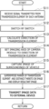
- each of the antennas 21 mounted in the antenna module 2 receives the RF signal transmitted from the transmission element P 1 in step S 11 .
- step S 12 the antenna module 2 switches on and off of the RF switch 22 to sequentially select the output of the RF signal received by each antenna 21 and outputs the selected one to the direction detection unit 11 .
- step S 13 the direction detection unit 11 calculates the direction of the transmission element P 1 based on the phase differences among the received signals received by the individual antennas 21 .
- step S 14 the drive mechanism 33 of the camera module 3 performs control to drive and rotate the fixing base 32 illustrated in FIG. 3 or 4 around the rotation axis x 2 such that the imaging axis x 1 of the camera 31 is oriented in the direction of the transmission element P 1 .
- step S 15 the camera 31 captures an image in the direction of the transmission element P 1 and outputs the captured image to the image processing unit 13 .
- step S 16 the image processing unit 13 adds the marker M 1 indicating the direction of the transmission element P 1 to the image captured by the camera 31 .
- the camera 31 captures the image D 1 of the surroundings including the pet 51 .
- the image processing unit 13 generates an image in which the marker M 1 is added to the captured image D 1 .
- step S 17 the communication unit 19 transmits the image generated by the image processing unit 13 to an external device.
- the image generated by the image processing unit 13 is displayed on the display 5 mounted in the external device such as a smartphone carried by the user, for example.
- the user can recognize the image including the transmission element P 1 , that is, the image of the pet 51 , at a remote location, for example.
- the transmission element imaging device 100 receives a signal (e.g., an RF signal) transmitted from the transmission element P 1 such as a beacon by use of the plurality of antennas 21 and calculates the direction of the transmission element P 1 based on the signal received by each antenna 21 .
- a signal e.g., an RF signal
- the fixing base 32 is driven such that the imaging axis x 1 of the camera 31 is oriented in the direction of the transmission element P 1 . Therefore, the imaging axis x 1 of the camera 31 can be oriented in the direction of the transmission element P 1 , and the camera 31 can capture an image in the direction in which the transmission element P 1 is present. For example, if the transmission element P 1 is attached to a collar of the pet 51 , the camera 31 can capture an image of the pet 51 , and the user can view the image of the pet 51 at a remote location. Thus, the user can remotely monitor how the pet 51 left in the house is doing.
- the marker M 1 which indicates the position of the transmission element P 1
- the captured image D 1 including the transmission element P 1 and the resultant image is displayed the user can easily recognize the position of the transmission element P 1 in the image. For example, if there is an obstacle between the vehicle V 1 and the transmission element P 1 , the transmission element P 1 is behind the obstacle and is not displayed in the image captured by the camera 31 . Even in such a case, since the marker M 1 is added, the user can recognize the position of the transmission element P 1 in the image.
- the camera 31 can capture an image of the transmission element P 1 from the suitable distance. Therefore, the camera 31 can capture a good panoramic image of the transmission element P 1 .
- the camera 31 captures an image of the transmission element P 1 by directing the imaging axis x 1 of the camera 31 toward the direction of the transmission element P 1 .
- the distance from the position of the camera 31 to that of the transmission element P 1 is calculated.
- the calculated distance is superimposed on the captured image, and the resultant image is displayed. Since the device configuration is the same as that of FIGS. 1 and 2 described above, the description of the device configuration is omitted.
- each of the antennas 21 mounted in the antenna module 2 receives the RF signal transmitted from the transmission element P 1 in step S 31 .
- step S 32 the antenna module 2 switches on and off of the RF switch 22 to sequentially select the output of the RF signal received by each antenna 21 and outputs the selected output to the direction detection unit 11 .
- step S 33 the direction detection unit 11 calculates the direction of the transmission element P 1 based on the phase differences among the received signals received by the individual antennas 21 .
- step S 34 the drive mechanism 33 of the camera module 3 performs control to drive and rotate the fixing base 32 illustrated in FIG. 3 or 4 around the rotation axis x 2 such that the imaging axis x 1 of the camera 31 is oriented in the direction of the transmission element P 1 .
- step S 35 the camera 31 captures an image in the direction of the transmission element P 1 and outputs the captured image to the image processing unit 13 .
- step S 36 the vehicle direction setting unit 15 determines whether or not to cause the vehicle V 1 to move. As described above, it is necessary to capture an image of the transmission element P 1 at multiple positions to calculate the distance from the camera 31 to the transmission element P 1 .
- the processing proceeds to step S 37 . Otherwise (S 36 ; NO), the processing proceeds to step S 38 .
- step S 37 the vehicle direction setting unit 15 sets the moving direction of the vehicle V 1 .
- the drive unit 4 causes the vehicle V 1 to move to the second position. After that, the processing returns to step S 31 .
- step S 38 the moving distance calculation unit 14 calculates the moving direction and the moving distance of the vehicle V 1 based on the angular velocity and acceleration detected by the gyro sensor 6 .
- step S 39 the depth distance calculation unit 18 calculates the distance from the camera 31 to the transmission element P 1 based on the images of the transmission element P 1 captured at the first and second positions.
- step S 40 the image processing unit 13 adds the marker M 1 indicating the direction of the transmission element P 1 and the distance to the transmission element P 1 to the image D 2 captured by the camera 31 and displays a resultant image.
- the image processing unit 13 generates an image in which the marker M 1 and the distance such as “depth xx m” are added to the captured image D 2 .
- step S 41 the communication unit 19 transmits the image generated by the image processing unit 13 to an external device.
- the image generated by the image processing unit 13 is displayed on the display 5 mounted in the external device such as a smartphone carried by the user, for example.
- the user can recognize the image including the transmission element P 1 , that is, the image of the pet 51 , at a remote location, for example.
- the transmission element imaging device 100 according to the second embodiment can obtain the same effects as the first embodiment described above.
- the vehicle V 1 is caused to move and capture an image of the transmission element P 1 at each of two positions (the first position and the second position). Accordingly, the distance from the camera 31 to the transmission element P 1 can be calculated. The calculated distance is superimposed on the image of the transmission element P 1 , and the resultant image is displayed. Thus, for example, even if there is an obstacle between the camera 31 and the transmission element P 1 and the transmission element P 1 is not displayed in the image, the user can easily recognize the distance from the camera 31 to the transmission element P 1 .
- the transmission element imaging device 100 is mounted in a movable object such as the vehicle V 1 and moves.
- a monocular stereo camera is used as the camera 31 mounted in the camera module 3
- the transmission element imaging device 100 may be fixed to a predetermined position without being mounted in a movable object.
- the transmission element imaging device 100 has been described with reference to the functional block diagrams. However, the device may be implemented by hardware, software, or a combination thereof.
- Software operated by a processor included in the transmission element imaging device 100 according to the embodiments of the present disclosure may be stored in a random access memory (RAM), a flash memory, a read only memory (ROM), an erasable programmable ROM (EPROM), an electrically erasable and programmable ROM (EEPROM), or a register.
- RAM random access memory
- ROM read only memory
- EPROM erasable programmable ROM
- EEPROM electrically erasable and programmable ROM
- software operated by the processor included in the transmission element imaging device 100 may be stored in a hard disk drive (HDD), a removable disk, a compact disk ROM (CD-ROM), a database, a server, or other appropriate storage media.
- HDD hard disk drive
- CD-ROM compact disk ROM
- database a server, or other appropriate storage media.
Landscapes
- Engineering & Computer Science (AREA)
- Multimedia (AREA)
- Signal Processing (AREA)
- Studio Devices (AREA)
- Closed-Circuit Television Systems (AREA)
Abstract
Description
Claims (9)
Applications Claiming Priority (2)
| Application Number | Priority Date | Filing Date | Title |
|---|---|---|---|
| JP2021-127979 | 2021-08-04 | ||
| JP2021127979A JP2023022898A (en) | 2021-08-04 | 2021-08-04 | Transmission element imaging apparatus and transmission element imaging method |
Publications (2)
| Publication Number | Publication Date |
|---|---|
| US20230042935A1 US20230042935A1 (en) | 2023-02-09 |
| US12309486B2 true US12309486B2 (en) | 2025-05-20 |
Family
ID=85151889
Family Applications (1)
| Application Number | Title | Priority Date | Filing Date |
|---|---|---|---|
| US17/817,047 Active 2043-03-22 US12309486B2 (en) | 2021-08-04 | 2022-08-03 | Transmission element imaging device and transmission element imaging method |
Country Status (2)
| Country | Link |
|---|---|
| US (1) | US12309486B2 (en) |
| JP (1) | JP2023022898A (en) |
Families Citing this family (1)
| Publication number | Priority date | Publication date | Assignee | Title |
|---|---|---|---|---|
| JP2024130637A (en) * | 2023-03-15 | 2024-09-30 | 株式会社トプコン | Receiving device, transmitting device, and transmitting/receiving system |
Citations (7)
| Publication number | Priority date | Publication date | Assignee | Title |
|---|---|---|---|---|
| US20180035056A1 (en) * | 2015-04-24 | 2018-02-01 | Hewlett-Packard Development Company, L.P. | Tracking a target with an imaging system |
| US20200084373A1 (en) * | 2018-09-12 | 2020-03-12 | Kabushiki Kaisha Toshiba | Imaging device, imaging system, and imaging method |
| US20200338742A1 (en) * | 2019-04-26 | 2020-10-29 | Fanuc Corporation | Unmanned transfer robot system |
| US20210216786A1 (en) * | 2020-01-14 | 2021-07-15 | Panasonic Intellectual Property Management Co., Ltd. | Indoor camera and action log recording system |
| US20220111522A1 (en) * | 2019-01-31 | 2022-04-14 | Lg Electronics Inc. | Mobile robot and control method therefor |
| US20220211010A1 (en) * | 2020-12-10 | 2022-07-07 | Samsung Electronics Co., Ltd. | Pet care system, pet care robot and method for controlling pet care robot |
| US11711616B2 (en) * | 2020-05-12 | 2023-07-25 | Electroapp, Llc | Portable system including motorized base controller and transmitter for tracking a moving target |
Family Cites Families (13)
| Publication number | Priority date | Publication date | Assignee | Title |
|---|---|---|---|---|
| JP2000121354A (en) * | 1998-10-16 | 2000-04-28 | Japan Aviation Electronics Industry Ltd | Distance measurement method |
| JP2004239745A (en) * | 2003-02-06 | 2004-08-26 | Hitachi Ltd | Planar antenna, mobile object position detection system |
| JP3756495B2 (en) * | 2003-07-04 | 2006-03-15 | 株式会社東芝 | Wave source visualization device |
| JP2006308493A (en) * | 2005-04-28 | 2006-11-09 | Ntt Docomo Inc | Portable terminal device, response communication device, and search target display system and method |
| JP2007101421A (en) * | 2005-10-05 | 2007-04-19 | Auto Network Gijutsu Kenkyusho:Kk | Perimeter monitoring sensor unit and perimeter monitoring sensor system |
| JP2011529181A (en) * | 2008-07-24 | 2011-12-01 | コーニンクレッカ フィリップス エレクトロニクス エヌ ヴィ | Distance measurement |
| JP5351466B2 (en) * | 2008-08-18 | 2013-11-27 | 大成建設株式会社 | Radio source visualization device |
| US9291695B2 (en) * | 2012-08-06 | 2016-03-22 | Fluke Corporation | Real-time RF signal visualization device |
| CN106842187A (en) * | 2016-12-12 | 2017-06-13 | 西南石油大学 | Positioner and its method are merged in a kind of phase-array scanning with Computer Vision |
| CL2016003302A1 (en) * | 2016-12-22 | 2017-09-15 | Univ Chile | Radiovision device |
| KR102566959B1 (en) * | 2016-12-27 | 2023-08-14 | 주식회사 에이치엘클레무브 | Radar apparatus |
| WO2018221204A1 (en) * | 2017-05-31 | 2018-12-06 | 日本電産株式会社 | Mobile body provided with radio antenna, and vehicle dispatch system |
| US11320509B2 (en) * | 2018-04-17 | 2022-05-03 | Apple Inc. | Electronic devices with motion sensing and angle of arrival detection circuitry |
-
2021
- 2021-08-04 JP JP2021127979A patent/JP2023022898A/en active Pending
-
2022
- 2022-08-03 US US17/817,047 patent/US12309486B2/en active Active
Patent Citations (8)
| Publication number | Priority date | Publication date | Assignee | Title |
|---|---|---|---|---|
| US20180035056A1 (en) * | 2015-04-24 | 2018-02-01 | Hewlett-Packard Development Company, L.P. | Tracking a target with an imaging system |
| US20200084373A1 (en) * | 2018-09-12 | 2020-03-12 | Kabushiki Kaisha Toshiba | Imaging device, imaging system, and imaging method |
| US20220111522A1 (en) * | 2019-01-31 | 2022-04-14 | Lg Electronics Inc. | Mobile robot and control method therefor |
| US20200338742A1 (en) * | 2019-04-26 | 2020-10-29 | Fanuc Corporation | Unmanned transfer robot system |
| JP2020181485A (en) | 2019-04-26 | 2020-11-05 | ファナック株式会社 | Unmanned transportation robot system |
| US20210216786A1 (en) * | 2020-01-14 | 2021-07-15 | Panasonic Intellectual Property Management Co., Ltd. | Indoor camera and action log recording system |
| US11711616B2 (en) * | 2020-05-12 | 2023-07-25 | Electroapp, Llc | Portable system including motorized base controller and transmitter for tracking a moving target |
| US20220211010A1 (en) * | 2020-12-10 | 2022-07-07 | Samsung Electronics Co., Ltd. | Pet care system, pet care robot and method for controlling pet care robot |
Also Published As
| Publication number | Publication date |
|---|---|
| US20230042935A1 (en) | 2023-02-09 |
| JP2023022898A (en) | 2023-02-16 |
Similar Documents
| Publication | Publication Date | Title |
|---|---|---|
| US10949798B2 (en) | Multimodal localization and mapping for a mobile automation apparatus | |
| CN109360245B (en) | Extrinsic parameter calibration method for multi-camera system of unmanned vehicle | |
| KR101776823B1 (en) | A mobile robot localization method and system via indoor surveillance cameras | |
| JP2012235712A (en) | Automatic mower with mowing situation monitoring function | |
| US20180239351A1 (en) | Autonomous mobile device | |
| CN112740009A (en) | Vehicle inspection system | |
| US12309486B2 (en) | Transmission element imaging device and transmission element imaging method | |
| US20220180559A1 (en) | On-Site Calibration for Mobile Automation Apparatus | |
| KR101040528B1 (en) | Terrain sensor assembly and autonomous mobile platform | |
| KR20160056559A (en) | Traveling system and method of robot using a pointer | |
| US20230410624A1 (en) | Notification system and notification method | |
| CN110945510A (en) | Method for spatial measurement by means of a measuring vehicle | |
| US10958846B2 (en) | Method, device and system for configuration of a sensor on a moving object | |
| JP2019109772A (en) | Moving body | |
| US12493300B2 (en) | System and magnetic marker detection method | |
| WO2021230884A1 (en) | Calibration system and method for data capture system | |
| EP3547663A1 (en) | Panaoramic vision system with parallax mitigation | |
| EP4455821B1 (en) | Working robot system | |
| JP2019091961A (en) | Camera control unit | |
| EP4019897B1 (en) | Autonomous travel system | |
| JP6026307B2 (en) | System and method for acquiring information indicating direction of moving object | |
| JP7153442B2 (en) | moving body | |
| JP2007290077A (en) | Autonomous mobile body and information construction system | |
| JP2023037656A (en) | Self-propelled moving device | |
| Stanèiæ et al. | A novel low-cost adaptive scanner concept for mobile robots |
Legal Events
| Date | Code | Title | Description |
|---|---|---|---|
| AS | Assignment |
Owner name: ROHM CO., LTD., JAPAN Free format text: ASSIGNMENT OF ASSIGNORS INTEREST;ASSIGNORS:YAGUMA, HIROSHI;YASUDA, MASHIRO;REEL/FRAME:060705/0149 Effective date: 20220714 |
|
| FEPP | Fee payment procedure |
Free format text: ENTITY STATUS SET TO UNDISCOUNTED (ORIGINAL EVENT CODE: BIG.); ENTITY STATUS OF PATENT OWNER: LARGE ENTITY |
|
| STPP | Information on status: patent application and granting procedure in general |
Free format text: DOCKETED NEW CASE - READY FOR EXAMINATION |
|
| STPP | Information on status: patent application and granting procedure in general |
Free format text: NON FINAL ACTION MAILED |
|
| STPP | Information on status: patent application and granting procedure in general |
Free format text: RESPONSE TO NON-FINAL OFFICE ACTION ENTERED AND FORWARDED TO EXAMINER |
|
| STPP | Information on status: patent application and granting procedure in general |
Free format text: FINAL REJECTION MAILED |
|
| STPP | Information on status: patent application and granting procedure in general |
Free format text: ADVISORY ACTION MAILED |
|
| STPP | Information on status: patent application and granting procedure in general |
Free format text: DOCKETED NEW CASE - READY FOR EXAMINATION |
|
| STPP | Information on status: patent application and granting procedure in general |
Free format text: NOTICE OF ALLOWANCE MAILED -- APPLICATION RECEIVED IN OFFICE OF PUBLICATIONS |
|
| STCF | Information on status: patent grant |
Free format text: PATENTED CASE |