US12307622B2 - Method and device for dewarping a region of a fisheye view image - Google Patents
Method and device for dewarping a region of a fisheye view image Download PDFInfo
- Publication number
- US12307622B2 US12307622B2 US17/835,254 US202217835254A US12307622B2 US 12307622 B2 US12307622 B2 US 12307622B2 US 202217835254 A US202217835254 A US 202217835254A US 12307622 B2 US12307622 B2 US 12307622B2
- Authority
- US
- United States
- Prior art keywords
- dewarping
- roi
- temporary
- shaped edge
- view image
- Prior art date
- Legal status (The legal status is an assumption and is not a legal conclusion. Google has not performed a legal analysis and makes no representation as to the accuracy of the status listed.)
- Active, expires
Links
Images


Classifications
-
- G—PHYSICS
- G06—COMPUTING OR CALCULATING; COUNTING
- G06T—IMAGE DATA PROCESSING OR GENERATION, IN GENERAL
- G06T3/00—Geometric image transformations in the plane of the image
- G06T3/04—Context-preserving transformations, e.g. by using an importance map
- G06T3/047—Fisheye or wide-angle transformations
-
- G—PHYSICS
- G06—COMPUTING OR CALCULATING; COUNTING
- G06T—IMAGE DATA PROCESSING OR GENERATION, IN GENERAL
- G06T3/00—Geometric image transformations in the plane of the image
- G06T3/18—Image warping, e.g. rearranging pixels individually
-
- G—PHYSICS
- G06—COMPUTING OR CALCULATING; COUNTING
- G06T—IMAGE DATA PROCESSING OR GENERATION, IN GENERAL
- G06T5/00—Image enhancement or restoration
- G06T5/80—Geometric correction
-
- G—PHYSICS
- G06—COMPUTING OR CALCULATING; COUNTING
- G06T—IMAGE DATA PROCESSING OR GENERATION, IN GENERAL
- G06T7/00—Image analysis
- G06T7/60—Analysis of geometric attributes
- G06T7/62—Analysis of geometric attributes of area, perimeter, diameter or volume
-
- G—PHYSICS
- G06—COMPUTING OR CALCULATING; COUNTING
- G06V—IMAGE OR VIDEO RECOGNITION OR UNDERSTANDING
- G06V10/00—Arrangements for image or video recognition or understanding
- G06V10/20—Image preprocessing
- G06V10/25—Determination of region of interest [ROI] or a volume of interest [VOI]
-
- G—PHYSICS
- G06—COMPUTING OR CALCULATING; COUNTING
- G06V—IMAGE OR VIDEO RECOGNITION OR UNDERSTANDING
- G06V10/00—Arrangements for image or video recognition or understanding
- G06V10/40—Extraction of image or video features
- G06V10/44—Local feature extraction by analysis of parts of the pattern, e.g. by detecting edges, contours, loops, corners, strokes or intersections; Connectivity analysis, e.g. of connected components
Definitions
- the present disclosure belongs to methods and devices for dewarping a region of a fisheye view image.
- a fisheye view image is an image having a wide field of view. Such a fisheye view image is captured by a fisheye lens to monitor a surrounding environment. Naturally, however, a fisheye view image is distorted due to the wide-angle capture of the surrounding environment, thereby obscuring object features of an object in the image, the degree of distortion being dependent on a position in the fisheye view image. To make features of an object less obscured, the fisheye view image may be dewarped to, at least partly, recover the true geometry of the object.
- a computer implemented method for dewarping a region of a fisheye view image wherein the fisheye view image is captured by a fisheye lens camera and comprises a first dewarping pole, DP 1 , the method comprising:
- the ROI may comprise an object to be used in an object detection, object classification, and/or object recognition algorithm.
- the algorithm(s) may be performed after a dewarping of the ROI has been performed, thereby providing a less distorted image on which the algorithm(s) is/are performed. Hence, the algorithm(s) may become more robust.
- the dewarped image may become more friendly for human visualization when viewing the image or a video stream of images.
- the present disclosure may provide a computationally efficient approach for dewarping a portion of a fisheye view image. This may allow for an accurate object detection, classification and/or recognition being performed in real time. Hence, computation time and computer power may be saved.
- the dewarping annulus sector region may be set such that its dewarping outer arc shaped edge is maintained at a same radial distance from DP 1 as the temporary outer arc shaped edge. Hence, an efficient setting of the dewarping outer arc shaped edge is provided, which may save processing time and/or processing power.
- the method may further comprise calculating D to be equal to a radial distance, R, between G of the ROI and a point, P 1 , on an edge of the fisheye view image such that DP 2 , G and P 1 are located on a same straight line, wherein G is located between DP 2 and P 1 .
- the method may further comprise calculating D to be equal to a radial distance, R, between G of the ROI and a point, P 1 , on an edge of the fisheye view image such that DP 2 , G and P 1 are located on a same straight line, wherein G is located between DP 2 and P 1 , wherein a tolerance of the dewarping pole moving distance D may be a radial extension, R ROI , of the ROI such that R ⁇ R ROI ⁇ D ⁇ R+R ROI .
- the definition of DP 2 may comprise:
- the dewarping of the dewarping annulus sector region of the fisheye view image may comprise, by a coordinate transformation, calculating a transformation from a spherical-coordinate representation of the dewarping annulus region to a rectilinear-coordinate representation projection of the dewarping annulus region, the dewarping annulus sector region thereby being an equirectangular projection of the fisheye view image.
- the threshold arc ratio may be a set of threshold arc ratios, wherein each threshold arc ratio of the set of threshold arc ratios belongs to a specific annulus region of a field of view, FOV, of the fisheye lens camera.
- FOV field of view
- different regions of the fisheye view image being associated with different threshold arc ratios may enhance an accurate dewarping of respective regions, thereby facilitating object detection.
- a non-transitory computer-readable storage medium having stored thereon instructions for implementing the method according to the first aspect, when executed on a device having processing capabilities.
- an electronic device comprising circuitry configured to execute:
- the dewarping annulus sector region setting function may comprise a shifting function configured to set the dewarping annulus sector region such that its dewarping outer arc shaped edge is maintained at a same radial distance from DP 1 as the temporary outer arc shaped edge.
- the circuitry may further be configured to execute
- the dewarping pole defining function may further be configured to, by a distance calculating function configured to calculate D to be equal to a radial distance, R, between G of the ROI and a point, P 1 , on an edge of the fisheye view image such that DP 2 , G and P 1 are located on a same straight line, wherein G is located between DP 2 and P 1 , include a tolerance of the dewarping pole moving distance D being a radial extension, R ROI , of the ROI such that: R ⁇ R ROI ⁇ D ⁇ R+R ROI .
- the dewarping pole defining function may comprise:
- the fisheye lens image may be an equirectangular projection of an environment comprising the dewarping annulus region, and wherein the dewarping function is further configured to, by a coordinate transformation, calculate a transformation from the equirectangular projection of the dewarping annulus region to a rectilinear projection of the dewarping annulus region.
- FIG. 1 shows a flowchart of a method for dewarping a region in a fisheye view image.
- FIG. 2 schematically shows a fisheye view image.
- FIG. 3 schematically shows a dewarping pole shift of a fisheye view image.
- FIG. 4 schematically shows further details in connection with a definition of a second dewarping pole of a fisheye view image.
- FIG. 5 schematically shows a tolerance of a dewarping pole shift of a fisheye view image.
- FIGS. 6 A- 6 D show further details of how to calculate a dewarping pole shift of a fisheye view image.
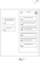
- FIG. 7 schematically shows an electronic device on which the disclosed method is implemented.
- FIG. 1 schematically shows a flowchart of an example of a method 100 for dewarping a region of a fisheye view image 200 , wherein the fisheye view image is captured by a fisheye lens camera and comprises a first dewarping pole, DP 1 .
- DP 1 may be an optical center of the fisheye view image 200 .
- FIG. 1 may advantageously be viewed together with FIGS. 2 and 3 below.
- the fisheye view image 100 may be acquired by a camera having mounted thereon any adequate type of fisheye lens, such as a circular.
- raw data of the fisheye view image 200 is such that an edge of a set of activated pixels forms a substantially circular geometry, such that the first dewarping pole, DP 1 , may be viewed as an origin of a polar coordinate system of the fisheye view image.
- any pixel in the fisheye view image 200 may be associated with a polar coordinate, thereby having a radial variable and an angular variable.
- the polar coordinate system may equivalently be represented in a complex plane.
- a dewarping of the fisheye view image 200 generally require considering spherical coordinates, i.e., an additional angular variable, to be dewarped onto an equirectangular projection. This will be further described below.
- the method 100 comprises defining 110 a region of interest, ROI, within the fisheye view image 200 .
- the ROI may be acquired from an image segmentation algorithm, an edge detection algorithm, etc., applied to the fisheye image 200 .
- the ROI may comprise an object in the fisheye view image 200 .
- the ROI may comprise a car, a truck, a person, etc.
- the ROI preferably substantially enclose an edge of the object, such as the car, the truck, or the person, to possibly be subsequently processed in an object detection, an object classification, and/or an object recognition algorithm.
- the ROI entirely enclose the edge of the object.
- the ROI may comprise a plurality of nearby objects.
- Examples thereof may be a group of people, a person riding on a bike, or the like.
- a ROI comprising a plurality of nearby objects, i.e., such a ROI may substantially enclose an edge of the plurality of nearby objects.
- a group of people this may imply that the group of people may be enclosed by a polygon possibly being optimized to minimize an area of the ROI.
- the method 100 further comprises determining 120 a center, G, of the ROI.
- G can be calculated, or at least estimated, using any calculation method, such as methods based on pixels enclosed by the edge of the ROI and positions of these pixels, etc.
- the center, G may be a center of gravity of the ROI.
- the center, G may be a center of a temporary annulus sector region 210 , further described below. In such a situation, the center, G, may be located on a radially and angularly centered point of the temporary annulus sector region 210 .
- a radial coordinate of the center, G may be a mean value of a maximal radial extension of the ROI
- an angular coordinate of the center, G may be a mean value of a maximal angular extension of the ROI.
- the center, G is a center of gravity of the ROI, it is appreciated that the center, G, may be located outside an edge of the ROI, should the ROI have a highly irregular geometry. The same may be true regarding the alternative procedures of determining the center, G.
- the method 100 further comprises defining 130 a temporary annulus sector region 210 of the fisheye view image 200 such that the temporary annulus sector region 210 comprises the ROI, and such that the temporary annulus sector region 210 has its center at DP 1 and has a temporary outer arc shaped edge 212 and a temporary inner arc shaped edge 214 .
- the temporary annulus sector region 210 may substantially be a mathematical annulus sector region.
- the inner arc shaped edge 214 may be associated with a first circle
- the outer arc shaped edge 212 may be associated with a second circle, the first and second circle having different radii, r 1 , r 2 .
- a ratio between these radii may lie in the range 0.9 ⁇ r 1 /r 2 ⁇ 1.1.
- r 1 /r 2 is a number being relatively close to 1 such that being in the range 0.98 ⁇ r 1 /r 2 ⁇ 1.02.
- the method 100 further comprises defining 140 a second dewarping pole, DP 2 , in the fisheye view image 200 at a dewarping pole moving distance, D, from DP 1 along a radial direction extending from G of the ROI through the DP 1 .
- the radial direction hence substantially coincides with a radial variable of the polar coordinate system of the fisheye view image 100 .
- the radial direction is further directed such that DP 1 is located between DP 2 and G. This is schematically illustrated in FIG. 3 .
- the method 100 further comprises setting 150 a dewarping annulus sector region 310 of the fisheye view image 200 such that the dewarping annulus sector region 310 comprises the ROI, and such that the dewarping annulus sector region 310 has its center at DP 2 and has its dewarping inner arc shaped edge maintained at a same radial distance r 1 from DP 1 as the temporary inner arc shaped edge.
- the shape of the dewarping inner arc shaped edge 314 differ from the inner arc shaped edge 214 , since a radius of curvature of the dewarping inner arc shaped edge 314 is larger than a radius of curvature of the inner arc shaped edge 214 after defining the second dewarping pole, DP 2 .
- a radius of curvature of a dewarping outer arc shaped edge 312 is larger than a radius of curvature of the outer arc shaped edge 212 after defining the second dewarping pole, DP 2 .
- a fisheye view image radius R 1 of a circular edge 202 of the fisheye view image 200 may differ from a radius R 2 of a second circle 302 having the second dewarping pole DP 2 as its center.
- the radii R 1 and R 2 have similar magnitudes.
- a ratio between these radii may lie in a range of 0.9 ⁇ R 1 /R 2 ⁇ 1.1. Notice that a shape and a scale of the ROI is similar before and after moving the dewarping pole.
- the method 100 further comprises dewarping 160 the dewarping annulus sector region 310 of the fisheye view image 200 .
- the dewarping 160 may be performed using any adequate transformation algorithm for dewarping between the coordinate system of the fisheye view image and an optional coordinate system.
- the optional coordinate system is a cartesian coordinate system, to substantially regain an undistorted geometry of the ROI provided the second dewarping pole, DP 2 , has been properly positioned as per the above.
- the substantially regained undistorted geometry of the ROI may then be used in, e.g., an object detection, classification and/or recognition algorithm.
- the dewarping annulus sector region 310 may be set such that its dewarping outer arc shaped edge 312 is maintained at a same radial distance from DP 1 as the temporary outer arc shaped edge 212 .
- r 2 and r 3 in FIGS. 2 and 3 may be substantially similar. It is thereby implied that an area of the dewarping annulus sector region 310 is smaller than an area of the temporary annulus sector region 210 .
- the method 100 may further comprise calculating D to be equal to a radial distance, R, between G of the ROI and a point, P 1 , on an edge 202 of the fisheye view image 200 such that DP 2 , G and P 1 are located on a same straight line L 1 , wherein G is located between DP 2 and P 1 .
- a tolerance of the dewarping pole moving distance D may be a radial extension, R ROI , of the ROI such that R ⁇ R ROI ⁇ D ⁇ R+R ROI .
- R ROI radial extension
- FIG. 5 A tolerance of the dewarping pole moving distance D may be a radial extension, R ROI , of the ROI such that R ⁇ R ROI ⁇ D ⁇ R+R ROI .
- R 2 >R 1 provided the dewarping outer arc shaped edge 312 is maintained at a same radial distance from DP 1 as the temporary outer arc shaped edge 212 , and the dewarping pole moving distance is D+d, d lying in the range 0 ⁇ d ⁇ R ROI .
- a preferred dewarping pole moving distance is the dewarping pole moving distance D as of, e.g., FIG. 4 .
- a case where the dewarping pole moving distance is larger than D is shown in FIG.
- a dewarping accuracy may be a tradeoff between the dewarping pole moving distance D, the radial extension R ROI of the ROI relative to the radius R 1 of the fisheye view image, and possibly the radial location of G of the ROI if, e.g., the ROI has a highly irregular geometry in the fisheye view image 200 .
- the definition of DP 2 may comprise calculating, by a first calculation procedure, a temporary arc ratio by a length AL 1 of the temporary outer arc shaped edge 212 divided by a length AL 2 of the temporary inner arc shaped edge 214 ; see FIG. 6 A .
- the temporary arc ratio may be calculated, by a second calculation procedure, by a length LL 1 of a line segment LL 1 joining a first and a second endpoint of the temporary outer arc shaped edge 212 divided by a length LL 2 of a line segment LL 2 joining a first and a second endpoint of the temporary inner arc shaped edge 214 ; FIG. 6 B .
- the definition of DP 2 may further comprise comparing the temporary arc ratio with a threshold arc ratio. Provided the temporary arc ratio exceeds the threshold arc ratio, calculation of D may be done by requiring a dewarping arc ratio to be equal to or below the threshold arc ratio.
- the dewarping arc ratio is calculated similarly as the temporary arc ratio, i.e., by a length AL 3 of the dewarping outer arc shaped edge 312 divided by a length AL 4 of the dewarping inner arc shaped edge 314 ; FIG. 6 C .
- the dewarping arc ratio may be calculated by a length LL 3 of a line segment LL 3 joining a first and a second endpoint of the dewarping outer arc shaped edge 312 divided by a length LL 4 of a line segment LL 4 joining a first and a second endpoint of the dewarping inner arc shaped edge 314 ; FIG. 6 D . Again, it is appreciated that these calculation procedures yield similar ratios.
- a common second dewarping pole, DP 2 of these arcs can be readily obtained.
- the location of the second dewarping pole, DP 2 can be calculated iteratively. In such a situation, DP 2 , may be initially located by a random or qualified guess, whereafter the arc ratio is calculated. If the arc ratio lies outside the threshold arc ratio, the location of DP 2 is to be updated accordingly. The updating may be performed using any adequate technique, such as utilizing Monte Carlo methods or the like.
- the dewarping 160 of the dewarping annulus sector region 310 of the fisheye view image 200 may comprise, by a coordinate transformation, calculating a transformation from a spherical-coordinate representation of the dewarping annulus region to a rectilinear-coordinate representation of the dewarping annulus region 310 .
- the dewarping annulus sector region 310 may thereby be viewed as an equirectangular projection of the fisheye view image 200 .
- a local degree of image distortion depends on a location of a specific image region of the spherical image. For instance, mapping the surface of Earth, being a spherically shaped two-dimensional surface, onto a flat two-dimensional surface induces a local image distortion being inversely proportional to a distance to the North- or the South pole, whereas the local distortion is minimal in vicinity of the Equator.
- the apparent area of Antarctica in such a projection is often mapped being excessively large relative to continents located closer to the Equator such as Africa or Central America.
- a real-world area ratio between Antarctica and Africa differ significantly compared to a two-dimensional representation of these continents.
- specific locations on the spherical image may be configured to be subject to minimal distortion. Shifting the location of a geometrical pole may thereby reduce a local distortion on a certain location while, simultaneously, increasing a local distortion in other locations.
- the first dewarping pole, DP 1 of the fisheye view image 200 may be viewed as the above-described geometrical pole when representing the fisheye view image 200 by a half sphere in a spherical coordinate system.
- the definition of the second dewarping pole, DP 2 may thereby be viewed as moving the geometrical pole to reduce a local distortion of the ROI.
- FIG. 7 there is shown, highly schematically, an electronic device 400 on which the above-described method 100 is implemented.
- the electronic device 400 has already been described in connection with the method above. To avoid undue repetition, reference is made to the above, when applicable.
- the electronic device 400 may comprise a device 410 for capturing a digital representation of a physical structure of an environment.
- the device may be an ordinary digital camera for, e.g., ceiling or wall mounting, comprising an imaging sensor.
- the electronic device 400 may further comprise a fisheye lens 412 for providing a fisheye view image 200 .
- the fisheye lens 412 may be of any type, as per the above description.
- the electronic device 400 further comprises circuitry 420 .
- the circuitry 420 is configured to execute a region of interest, ROI, defining function 421 configured to define a ROI within the fisheye view image 200 .
- the circuitry 420 is further configured to execute a center determining function 422 configured to determine a center, G, of the ROI.
- the circuitry 420 is further configured to execute a temporary annulus sector region defining function 423 configured to define a temporary annulus sector region 210 of the fisheye view image 200 such that the temporary annulus sector region 210 comprises the ROI, and such that the temporary annulus sector region 210 has its center at a first dewarping pole, DP 1 , of the fisheye view image 200 and has a temporary outer arc shaped edge 212 and a temporary inner arc shaped edge 214 .
- a temporary annulus sector region defining function 423 configured to define a temporary annulus sector region 210 of the fisheye view image 200 such that the temporary annulus sector region 210 comprises the ROI, and such that the temporary annulus sector region 210 has its center at a first dewarping pole, DP 1 , of the fisheye view image 200 and has a temporary outer arc shaped edge 212 and a temporary inner arc shaped edge 214 .
- the circuitry 420 is further configured to execute a dewarping pole defining function 424 configured to define a second dewarping pole, DP 2 , in the fisheye view image 200 at a dewarping pole moving distance, D, from DP 1 along a radial direction extending from G of the ROI through the DP 1 .
- the circuitry 420 is further configured to execute a dewarping annulus sector region setting function 425 configured to set a dewarping annulus sector region 310 of the fisheye view 200 image such that the dewarping annulus sector region 310 comprises the ROI, and such that the dewarping annulus sector region 310 has its center at DP 2 and has its dewarping inner arc shaped edge 314 maintained at a same radial distance R 1 from DP 1 as the temporary inner arc shaped edge 214 .
- the circuitry 420 is further configured to execute a dewarping function 426 configured to dewarp the dewarping annulus sector region 310 of the fisheye view image 200 .
- the dewarping annulus sector region setting function 425 may comprise a shifting function configured to set the dewarping annulus sector region 310 such that its dewarping outer arc shaped edge 312 is maintained at a same radial distance from DP 1 as the temporary outer arc shaped edge 212 .
- the circuitry 420 may be further configured to execute a distance calculating function configured to calculate D to be equal to a radial distance, R, between G of the ROI and a point, P 1 , on an edge 202 of the fisheye view image such that DP 2 , G and P 1 are located on a same straight line L 1 , wherein G is located between DP 2 and P 1 .
- the dewarping pole defining function 424 may further be configured to, by a distance calculating function configured to calculate D to be equal to a radial distance, R, between G of the ROI and a point, P 1 , on an edge of the fisheye view image such that DP 2 , G and P 1 are located on a same straight line L 1 , wherein G is located between DP 2 and P 1 , include a tolerance of the dewarping pole moving distance D being a radial extension, R ROI , of the ROI such that R ⁇ R ROI ⁇ D ⁇ R+R ROI .
- the dewarping pole defining function 424 may comprise a temporary arc ratio calculating function configured to calculate a temporary arc ratio by either of a length AL 1 of the temporary outer arc shaped edge 212 divided by a length AL 2 of the temporary inner arc shaped edge 214 or a length LL 1 of a line segment LL 1 joining a first and a second endpoint of the temporary outer arc shaped edge 212 divided by a length LL 2 of a line segment LL 2 joining a first and a second endpoint of the temporary inner arc shaped edge 214 .
- the dewarping pole defining function 424 may further comprise a comparing function configured to compare the temporary arc ratio with a threshold arc ratio.
- the dewarping pole defining function 424 may further comprise an arc ratio condition function configured to, provided the temporary arc ratio exceeds the threshold arc ratio, calculate D by requiring a dewarping arc ratio to be equal to or below the threshold arc ratio.
- the dewarping arc ratio may be calculated by either of a length AL 3 of the dewarping outer arc shaped edge 312 divided by a length AL 4 of the dewarping inner arc shaped edge 314 or a length LL 3 of a line segment joining a first and a second endpoint of the dewarping outer arc shaped edge 312 divided by a length LL 4 of a line segment joining a first and a second endpoint of the dewarping inner arc shaped edge 314 .
- the dewarping function 426 may further be configured to, by a coordinate transformation, calculate a transformation from spherical-coordinate representation of the dewarping annulus sector region 310 to a rectilinear-coordinate representation of the dewarping annulus sector region 310 , the dewarping annulus sector region thereby being an equirectangular projection of the fisheye view image 200 .
Landscapes
- Engineering & Computer Science (AREA)
- Physics & Mathematics (AREA)
- General Physics & Mathematics (AREA)
- Theoretical Computer Science (AREA)
- Computer Vision & Pattern Recognition (AREA)
- Multimedia (AREA)
- Geometry (AREA)
- Image Processing (AREA)
Abstract
Description
-
- defining a region of interest, ROI, within the fisheye view image,
- determining a center, G, of the ROI,
- defining a temporary annulus sector region of the fisheye view image such that the temporary annulus sector region comprises the ROI, and such that the temporary annulus sector region has its center at DP1 and has a temporary outer arc shaped edge and a temporary inner arc shaped edge,
- defining a second dewarping pole, DP2, in the fisheye view image at a dewarping pole moving distance, D, from DP1 along a radial direction extending from G of the ROI through the DP1,
- setting a dewarping annulus sector region of the fisheye view image such that the dewarping annulus sector region comprises the ROI, and such that the dewarping annulus sector region has its center at DP2 and has its dewarping inner arc shaped edge maintained at a same radial distance from DP1 as the temporary inner arc shaped edge, and
- dewarping the dewarping annulus sector region of the fisheye view image.
R−R ROI <D<R+R ROI.
-
- a length of the temporary outer arc shaped edge divided by a length of the temporary inner arc shaped edge, or
- a length of a line segment joining a first and a second endpoint of the temporary outer arc shaped edge divided by a length of a line segment joining a first and a second endpoint of the temporary inner arc shaped edge, comparing the temporary arc ratio with a threshold arc ratio,
- provided the temporary arc ratio exceeds the threshold arc ratio, calculating D by requiring a dewarping arc ratio to be equal to or below the threshold arc ratio, the dewarping arc ratio being calculated by either of:
- a length of the dewarping outer arc shaped edge divided by a length of the dewarping inner arc shaped edge, or
- a length of a line segment joining a first and a second endpoint of the dewarping outer arc shaped edge divided by a length of a line segment joining a first and a second endpoint of the dewarping inner arc shaped edge.
-
- a region of interest, ROI, defining function configured to define a ROI within a fisheye view image,
- a center determining function configured to determine a center of the ROI,
- a temporary annulus sector region defining function configured to define a temporary annulus sector region of the fisheye view image such that the temporary annulus sector region comprises the ROI, and such that the temporary annulus sector region has its center at a first dewarping pole, DP1, of the fisheye view image and has a temporary outer arc shaped edge and a temporary inner arc shaped edge,
- a dewarping pole defining function configured to define a second dewarping pole, DP2, in the fisheye view image at a dewarping pole moving distance, D, from DP1 along a radial direction extending from G of the ROI through the DP1,
- a dewarping annulus sector region setting function configured to set a dewarping annulus sector region of the fisheye view image such that the dewarping annulus sector region comprises the ROI, and such that the dewarping annulus sector region has its center at DP2 and has its dewarping inner arc shaped edge maintained at a same radial distance from DP1 as the temporary inner arc shaped edge, and
- a dewarping function configured to dewarp the dewarping annulus sector region of the fisheye view image.
-
- a distance calculating function configured to calculate D to be equal to a radial distance, R, between G of the ROI and a point, P1, on an edge of the fisheye view image such that DP2, G and P1 are located on a same straight line, wherein G is located between DP2 and P1.
R−R ROI <D<R+R ROI.
-
- a temporary arc ratio calculating function configured to calculate a temporary arc ratio by either of:
- a length of the temporary outer arc shaped edge divided by a length of the temporary inner arc shaped edge, or
- a length of a line segment joining a first and a second endpoint of the temporary outer arc shaped edge divided by a length of a line segment joining a first and a second endpoint of the temporary inner arc shaped edge,
- a comparing function configured to compare the temporary arc ratio with a threshold arc ratio,
- an arc ratio condition function configured to, provided the temporary arc ratio exceeds the threshold arc ratio, calculate D by requiring a dewarping arc ratio to be equal to or below the threshold arc ratio, wherein the dewarping arc ratio is calculated by either of:
- a length of the dewarping outer arc shaped edge divided by a length of the dewarping inner arc shaped edge, or
- a length of a line segment joining a first and a second endpoint of the dewarping outer arc shaped edge divided by a length of a line segment joining a first and a second endpoint of the dewarping inner arc shaped edge.
- a temporary arc ratio calculating function configured to calculate a temporary arc ratio by either of:
Claims (13)
R−R ROI <D<R+R ROI.
R−R ROI <D<D+R ROI.
Applications Claiming Priority (3)
| Application Number | Priority Date | Filing Date | Title |
|---|---|---|---|
| EP21178765 | 2021-06-10 | ||
| EP21178765.0A EP4102449B1 (en) | 2021-06-10 | 2021-06-10 | Method and device for dewarping a region of a fisheye view image |
| EP21178765.0 | 2021-06-10 |
Publications (2)
| Publication Number | Publication Date |
|---|---|
| US20220398687A1 US20220398687A1 (en) | 2022-12-15 |
| US12307622B2 true US12307622B2 (en) | 2025-05-20 |
Family
ID=76392153
Family Applications (1)
| Application Number | Title | Priority Date | Filing Date |
|---|---|---|---|
| US17/835,254 Active 2043-09-06 US12307622B2 (en) | 2021-06-10 | 2022-06-08 | Method and device for dewarping a region of a fisheye view image |
Country Status (4)
| Country | Link |
|---|---|
| US (1) | US12307622B2 (en) |
| EP (1) | EP4102449B1 (en) |
| JP (1) | JP7754774B2 (en) |
| CN (1) | CN115471396B (en) |
Citations (8)
| Publication number | Priority date | Publication date | Assignee | Title |
|---|---|---|---|---|
| US6243131B1 (en) | 1991-05-13 | 2001-06-05 | Interactive Pictures Corporation | Method for directly scanning a rectilinear imaging element using a non-linear scan |
| US6687387B1 (en) | 1999-12-27 | 2004-02-03 | Internet Pictures Corporation | Velocity-dependent dewarping of images |
| US20040032649A1 (en) | 2002-06-05 | 2004-02-19 | Tetsujiro Kondo | Method and apparatus for taking an image, method and apparatus for processing an image, and program and storage medium |
| KR20140117808A (en) | 2013-03-27 | 2014-10-08 | 정우하이테크 주식회사 | Device and method for calibrating image distortion of all around survillance camera |
| US9479732B1 (en) | 2015-11-10 | 2016-10-25 | Irobot Corporation | Immersive video teleconferencing robot |
| US20180374200A1 (en) * | 2017-06-21 | 2018-12-27 | Canon Kabushiki Kaisha | Information processing apparatus, information processing method, and recording medium |
| KR20190118076A (en) * | 2018-04-09 | 2019-10-17 | 한화테크윈 주식회사 | Camera system and method for processing image thereof |
| US20210118094A1 (en) | 2016-11-17 | 2021-04-22 | Intel Corporation | Spherical rotation for encoding wide view video |
Family Cites Families (8)
| Publication number | Priority date | Publication date | Assignee | Title |
|---|---|---|---|---|
| JP2656143B2 (en) * | 1990-08-27 | 1997-09-24 | シャープ株式会社 | Omnidirectional imaging device |
| JP5863374B2 (en) * | 2011-10-11 | 2016-02-16 | 本田技研工業株式会社 | Image processing method |
| JP6076103B2 (en) * | 2013-01-23 | 2017-02-08 | 本田技研工業株式会社 | Image processing method |
| JP2017162371A (en) * | 2016-03-11 | 2017-09-14 | カシオ計算機株式会社 | Image processing device, image processing method and program |
| JP2017208658A (en) * | 2016-05-17 | 2017-11-24 | キヤノン株式会社 | Image processing apparatus, image processing method, and program |
| KR102505951B1 (en) * | 2016-08-24 | 2023-03-03 | 한화테크윈 주식회사 | Apparatus and method for providing image, and computer program recorded on computer readable medium for excuting the method |
| JP6885133B2 (en) * | 2017-03-23 | 2021-06-09 | カシオ計算機株式会社 | Image processing equipment, imaging system, image processing method and program |
| CN108717704B (en) * | 2018-05-15 | 2021-05-28 | 珠海全志科技股份有限公司 | Target tracking method based on fisheye image, computer device and computer readable storage medium |
-
2021
- 2021-06-10 EP EP21178765.0A patent/EP4102449B1/en active Active
-
2022
- 2022-05-31 JP JP2022088266A patent/JP7754774B2/en active Active
- 2022-06-02 CN CN202210624974.1A patent/CN115471396B/en active Active
- 2022-06-08 US US17/835,254 patent/US12307622B2/en active Active
Patent Citations (8)
| Publication number | Priority date | Publication date | Assignee | Title |
|---|---|---|---|---|
| US6243131B1 (en) | 1991-05-13 | 2001-06-05 | Interactive Pictures Corporation | Method for directly scanning a rectilinear imaging element using a non-linear scan |
| US6687387B1 (en) | 1999-12-27 | 2004-02-03 | Internet Pictures Corporation | Velocity-dependent dewarping of images |
| US20040032649A1 (en) | 2002-06-05 | 2004-02-19 | Tetsujiro Kondo | Method and apparatus for taking an image, method and apparatus for processing an image, and program and storage medium |
| KR20140117808A (en) | 2013-03-27 | 2014-10-08 | 정우하이테크 주식회사 | Device and method for calibrating image distortion of all around survillance camera |
| US9479732B1 (en) | 2015-11-10 | 2016-10-25 | Irobot Corporation | Immersive video teleconferencing robot |
| US20210118094A1 (en) | 2016-11-17 | 2021-04-22 | Intel Corporation | Spherical rotation for encoding wide view video |
| US20180374200A1 (en) * | 2017-06-21 | 2018-12-27 | Canon Kabushiki Kaisha | Information processing apparatus, information processing method, and recording medium |
| KR20190118076A (en) * | 2018-04-09 | 2019-10-17 | 한화테크윈 주식회사 | Camera system and method for processing image thereof |
Non-Patent Citations (2)
| Title |
|---|
| Extended European Search Report dated Dec. 8, 2021 for European Patent Application No. 21178765.0. |
| Tai et al., "A Fully Automatic Approach for Fisheye Camera Calibration," 2018 IEEE Visual Communications and Image Processing (VCIP), (2018). |
Also Published As
| Publication number | Publication date |
|---|---|
| JP7754774B2 (en) | 2025-10-15 |
| JP2022189751A (en) | 2022-12-22 |
| US20220398687A1 (en) | 2022-12-15 |
| CN115471396B (en) | 2024-07-23 |
| EP4102449A1 (en) | 2022-12-14 |
| CN115471396A (en) | 2022-12-13 |
| EP4102449B1 (en) | 2023-08-16 |
Similar Documents
| Publication | Publication Date | Title |
|---|---|---|
| US10594941B2 (en) | Method and device of image processing and camera | |
| US10628916B2 (en) | Image generating apparatus, image generating method, and program | |
| JP5454674B2 (en) | Image generation apparatus, image generation program, synthesis table generation apparatus, and synthesis table generation program | |
| WO2020012756A1 (en) | Stereo imaging device | |
| JP5573618B2 (en) | Image processing program and image processing apparatus | |
| CN106780550B (en) | Target tracking method and electronic equipment | |
| CN102714694B (en) | Image processing apparatus, image processing method, integrated circuit, program | |
| JP5857269B2 (en) | Image generating apparatus, image generating method, and program | |
| US11417080B2 (en) | Object detection apparatus, object detection method, and computer-readable recording medium | |
| US20190045122A1 (en) | Image processing apparatus and image capturing apparatus | |
| KR20140090775A (en) | Correction method of distortion image obtained by using fisheye lens and image display system implementing thereof | |
| KR101324250B1 (en) | optical axis error compensation method using image processing, the method of the same, and the zoom camera provided for the compensation function of the optical axis error | |
| JP2003178309A (en) | Moving amount estimation device | |
| JP2019057864A (en) | Camera control method, camera controller and camera control program | |
| US12307622B2 (en) | Method and device for dewarping a region of a fisheye view image | |
| CN114742726B (en) | Blind spot detection method, device, electronic device and storage medium | |
| JP5215097B2 (en) | Conversion method of captured image | |
| CN113850905A (en) | A real-time stitching method of panoramic images for a cycle-scanning photoelectric warning system | |
| Li et al. | Fish-eye distortion correction based on midpoint circle algorithm | |
| JP2025069580A (en) | Image Processing System | |
| CN110786017B (en) | Distributing Image Generation Methods | |
| KR102498870B1 (en) | Camera system and method for processing image thereof | |
| US12531971B2 (en) | Monitoring apparatus, movable apparatus, and installation method for monitoring apparatus | |
| CN119478028B (en) | Unmanned aerial vehicle target positioning system and positioning method | |
| CN117746396B (en) | A Parking Environment Perception Method Based on Fisheye Camera |
Legal Events
| Date | Code | Title | Description |
|---|---|---|---|
| AS | Assignment |
Owner name: AXIS AB, SWEDEN Free format text: ASSIGNMENT OF ASSIGNORS INTEREST;ASSIGNORS:PETTERSSON, LUDVIG;CHEN, JIANDAN;BJOERGVINSDOTTIR, HANNA;SIGNING DATES FROM 20190826 TO 20220408;REEL/FRAME:060137/0575 |
|
| FEPP | Fee payment procedure |
Free format text: ENTITY STATUS SET TO UNDISCOUNTED (ORIGINAL EVENT CODE: BIG.); ENTITY STATUS OF PATENT OWNER: LARGE ENTITY |
|
| STPP | Information on status: patent application and granting procedure in general |
Free format text: DOCKETED NEW CASE - READY FOR EXAMINATION |
|
| STPP | Information on status: patent application and granting procedure in general |
Free format text: NON FINAL ACTION MAILED |
|
| STPP | Information on status: patent application and granting procedure in general |
Free format text: RESPONSE TO NON-FINAL OFFICE ACTION ENTERED AND FORWARDED TO EXAMINER |
|
| STPP | Information on status: patent application and granting procedure in general |
Free format text: AWAITING TC RESP., ISSUE FEE NOT PAID |
|
| STCF | Information on status: patent grant |
Free format text: PATENTED CASE |