US12306470B2 - Extended depth of focus ophthalmic lens designs based on continuous periodic refractive power profile - Google Patents
Extended depth of focus ophthalmic lens designs based on continuous periodic refractive power profile Download PDFInfo
- Publication number
- US12306470B2 US12306470B2 US17/651,101 US202217651101A US12306470B2 US 12306470 B2 US12306470 B2 US 12306470B2 US 202217651101 A US202217651101 A US 202217651101A US 12306470 B2 US12306470 B2 US 12306470B2
- Authority
- US
- United States
- Prior art keywords
- eyewear
- lens
- use case
- cycles
- periodic
- Prior art date
- Legal status (The legal status is an assumption and is not a legal conclusion. Google has not performed a legal analysis and makes no representation as to the accuracy of the status listed.)
- Active, expires
Links
Images


Classifications
-
- G—PHYSICS
- G02—OPTICS
- G02C—SPECTACLES; SUNGLASSES OR GOGGLES INSOFAR AS THEY HAVE THE SAME FEATURES AS SPECTACLES; CONTACT LENSES
- G02C7/00—Optical parts
- G02C7/02—Lenses; Lens systems ; Methods of designing lenses
- G02C7/06—Lenses; Lens systems ; Methods of designing lenses bifocal; multifocal ; progressive
-
- G—PHYSICS
- G02—OPTICS
- G02C—SPECTACLES; SUNGLASSES OR GOGGLES INSOFAR AS THEY HAVE THE SAME FEATURES AS SPECTACLES; CONTACT LENSES
- G02C7/00—Optical parts
- G02C7/02—Lenses; Lens systems ; Methods of designing lenses
- G02C7/04—Contact lenses for the eyes
- G02C7/041—Contact lenses for the eyes bifocal; multifocal
- G02C7/042—Simultaneous type
-
- G—PHYSICS
- G02—OPTICS
- G02C—SPECTACLES; SUNGLASSES OR GOGGLES INSOFAR AS THEY HAVE THE SAME FEATURES AS SPECTACLES; CONTACT LENSES
- G02C7/00—Optical parts
- G02C7/02—Lenses; Lens systems ; Methods of designing lenses
- G02C7/08—Auxiliary lenses; Arrangements for varying focal length
- G02C7/081—Ophthalmic lenses with variable focal length
- G02C7/083—Electrooptic lenses
-
- G—PHYSICS
- G02—OPTICS
- G02C—SPECTACLES; SUNGLASSES OR GOGGLES INSOFAR AS THEY HAVE THE SAME FEATURES AS SPECTACLES; CONTACT LENSES
- G02C7/00—Optical parts
- G02C7/02—Lenses; Lens systems ; Methods of designing lenses
- G02C7/024—Methods of designing ophthalmic lenses
- G02C7/028—Special mathematical design techniques
Definitions
- the application relates to eyewear, particular to eyewear for preferred use cases.
- Presbyopia is an ophthalmic condition where the eye loses the ability to focus near objects clearly due to lens aging. It can significantly affect the quality of life. Since eventually every person is undergoing this condition, it's important to find a solution to it.
- Spectacle-free treatment can be achieved by contact lenses and intraocular lenses.
- a lens with bi-focus, multi-focus or extended depth of focus (EDoF) allows clear vision of objects from far to near.
- Bifocal and trifocal diffractive lenses could extend depth of focus (DoF), but suffer from degraded image quality between focal points.
- Existing EDoF lens can hardly reach continuous and large (>2D) DoF.
- a method to provide EDoF ophthalmic lens designs based on continuous periodic refractive power profile includes: providing an underlying optical correction lens surface curve where needed; defining a periodic power map to provide a correction which emphasizes an individual use case, while still providing a functional DoF for other uses; mapping the periodic power curve to a physical lens curvature profile; where there is an underlying optical correction, superimposing the physical lens curvature profile over the underlying optical correction; and providing the combined underlying optical correction, if any, and physical lens curvature profile to physically manufacture an EDoF ophthalmic eyewear.
- the periodic power curve can include a plurality of about triangularly shaped power curves.
- mapping of one period can be defined by the equation:
- ⁇ ⁇ ( r ) A ⁇ ( r ) * t ⁇ r ⁇ i ⁇ ( ( 2 ⁇ r ⁇ M R ) N ) * P , where ⁇ is the power at a radial distance r from pupil center, P is a dioptric power range, N is an exponential power inside the triangular function ‘tri’, M determines the number of cycles within a pupil with radius R, and A(r) is a pupil apodization function that controls the overall power profile, and there are M cycles of such mapping across the pupil.
- the mapping of one period can also be defined by the equation:
- ⁇ ⁇ ( r ) A ⁇ ( r ) * sin ⁇ ( ( ⁇ ⁇ r ⁇ M R ) N ) * P , ( 0 ⁇ r ⁇ R M ) .
- the eyewear can include eyeglasses or at least one contact lens.
- the eyewear can include a Scleral lens.
- the eyewear can include an implantable intraocular lens.
- the eyewear can include an implantable ophthalmic lenses (IOL).
- IOL implantable ophthalmic lenses
- the eyewear can include laser refractive surgery.
- the eyewear can include an electronically-controlled lens.
- the eyewear can include a liquid crystal or a liquid lens.
- the periodic power curve can include an amplitude or amplitude variation for a given use case.
- the periodic power curve can include a periodicity or variation in periodicity for a given use case.
- the periodic power curve can include at least one cycle of a different cycle width than other cycles of the periodic power curve.
- the periodic power curve can include a cycle width variation between cycles.
- the periodic power curve can include a periodicity variation between cycles.
- the periodic power curve can include an amplitude variation between cycles.
- the use case can include reading eyewear or computer eyewear.
- the use case can include distance eyewear or driving eyewear.
- FIG. 1 is a drawing showing comparisons of monofocal and bifocal designs of the prior art compared to an exemplary extended depth of focus ophthalmic (EDoF) lens structure according to the Application (far right);
- EDOF extended depth of focus ophthalmic
- FIG. 2 is a drawing showing graphs an exemplary wavefront profile generated by a lens according to the Application
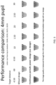
- FIG. 3 is a drawing showing a performance comparison for an exemplary 4 mm pupil
- FIG. 4 is a drawing showing a graph of an exemplary area MTF comparison at a 4 mm pupil
- FIG. 5 is a drawing comparing diffractive vs. refractive lens approaches
- FIG. 6 is a drawing showing graphs of an exemplary iterative refractive extended depth-of-focus design according to the Application;
- FIG. 7 is a drawing showing an example equation and corresponding graphs for an extended depth of focus ophthalmic (EDoF) lens designs based on continuous periodic refractive power profile according to the Application;
- EDOF extended depth of focus ophthalmic
- FIG. 8 is a drawing showing an example equation and corresponding graphs for an extended depth of focus ophthalmic (EDoF) lens designs based on a continuous periodic refractive power profile according to the Application optimized for far;
- EDOF extended depth of focus ophthalmic
- FIG. 9 is a drawing showing an example equation and corresponding graphs for an extended depth of focus ophthalmic (EDoF) lens designs based on continuous periodic refractive power profile according to the Application optimized for far and near;
- EDOF extended depth of focus ophthalmic
- FIG. 10 is a drawing showing a performance for an exemplary optimized design with a 4 mm pupil
- FIG. 11 is a drawing showing a graph illustrating how IREDoF can improve the intermediate range
- FIG. 12 is a drawing showing a schematic diagram of a special light simulator (SLM) for generating an aberration profile
- FIG. 13 is a drawing showing a performance for a simulation vs. a camera.
- FIG. 14 is a drawing showing a graph illustrating IREDoF visual acuity from 0D to 2.5D.
- Eyewear Eyewear as used hereinbelow and generally throughout the Application is expressly defined to include a variety of vision correction methods.
- the corrective structures and methods of the Application can be implemented by any suitable methods that are available now or in future. This includes (however, is not limited to) glasses, soft/hard/scleral contact lenses, implantable ophthalmic lenses (e.g. IOL), laser refractive surgery, electronically-controlled lenses (e.g. liquid crystal and liquid lens), etc.
- Eyewear does not require the addition of new components, where, for example, the structure of eyewear caused by laser refractive surgery is a newly modified and added structural shape to the original material of the human eye.
- Eyewear also expressly includes an implantable lens, such as an intraocular lens or an ophthalmic lens.
- Use Case is defined hereinbelow and generally throughout the application as a user preferred use case or a user needed use case, for example, eyewear preferred for reading or computer activities. Other use cases include, for example, distance, driving, etc.
- An individual use case of a corrected lens according to the Application is relatively easy to implement along with individualized (or customized) corrections based on patient's needs (e.g. an underlying patient prescription for normal corrective eyewear to correct aberrations of the patient's eye sight).
- Corrective lenses include, for example, eyeglasses contact lenses, and intraocular lenses. Corrective lenses typically correct for the optical aberrations of an individual's eyes. Typically, such corrections (e.g. eyewear optical prescriptions) include at least refractive corrections, commonly corrections for astigmatism, and possibly higher order and/or more unusual corrections, such as, for example for chromatic aberration.
- corrections e.g. eyewear optical prescriptions
- refractive corrections commonly corrections for astigmatism
- more unusual corrections such as, for example for chromatic aberration.
- Corrective lenses can be provided for eyewear according to a user's use case, including, for example, reading eyewear, computer eyewear, distance eyewear, driving eyewear, etc.
- Eyewear is typically in the form of eyeglasses or contact lenses.
- corrections can be written, such as, by a laser, directly onto a cornea of the eye.
- the new system and method applies a periodic power waveform which is transformed or mapped into a physical curvature which modifies the underlying correct lens surface.
- the modified lens surface can be manufactured using known eyewear production methods and materials. What is new is this secondary modification to the underlying corrective lens shape, or the new curvature alone, in the unusual case of no underlying correction.
- the new system and method begins with a periodic power waveform versus pupil coordinate.
- the amplitude of the periodic pattern can be adjusted and/or include an amplitude variation or modulation (however, typically is a constant amplitude).
- the periodicity can be varied for more cycles or less cycles yielding a control of granularity of the correction.
- the width of the cycles can be varied, together as above, or individually, that is, there can be different cycles widths.
- the periodic power curve can include a plurality of about triangularly shaped power curves.
- the equation of the Appendices can be adapted to other shapes, such as, for example,
- ⁇ ⁇ ( r ) A ⁇ ( r ) * sin ⁇ ( ( ⁇ ⁇ r ⁇ M R ) N ) * P , ( 0 ⁇ r ⁇ R M ) .
- Another goal of this Application is to propose a new approach to designing refractive presbyopia-correcting ophthalmic lenses with a large continuous DoF and pupil size independency.
- a design example was found and used to evaluate the performance through focus.
- the area MTF was well balanced through 2.5D of DoF for a range of pupil sizes (from 3 mm to 5 mm).
- the orientation of the 20/20 letter ‘E’ on a visual acuity chart was clearly recognized subjectively over defocus ranging from 0 to 2.5D.
- FIG. 1 is a drawing showing comparisons of monofocal (left: far) and bifocal (middle: near, far, near, far) designs of the prior art compared to an exemplary extended depth of focus ophthalmic (EDoF) lens structure based on continuous periodic refractive power profile according to the Application (right: far, near, far, near).
- EDOF extended depth of focus ophthalmic
- the transitional areas (circle) can be designed to go either from far to near or from near to far, including combinations thereof.
- FIG. 2 is a drawing showing graphs an exemplary wavefront profile generated by a lens according to the Application.
- P was a dioptric power range within each cycle
- N was the exponent of the expression inside the triangular function (tri).
- M determined the number of cycles within a pupil with radius R
- A(r) was an apodization function.
- FIG. 3 is a drawing showing a performance comparison for an exemplary 4 mm pupil.
- FIG. 4 is a drawing showing a graph of an exemplary area MTF comparison at a 4 mm pupil.
- FIG. 5 is a drawing comparing diffractive vs. refractive lens approaches.
- Drawbacks (cons) for diffractive approaches include, focus discontinuity, lack of flexibility, and difficult to manufacture.
- FIG. 6 is a drawing showing graphs of an exemplary iterative refractive extended depth-of-focus design according to the Application.
- FIG. 7 is a drawing showing an example equation and corresponding graphs for an extended depth of focus ophthalmic (EDoF) lens designs based on continuous periodic refractive power profile according to the Application.
- FIG. 8 is a drawing showing an example equation and corresponding graphs for an extended depth of focus ophthalmic (EDoF) lens designs based on a continuous periodic refractive power profile according to the Application optimized for far.
- FIG. 9 is a drawing showing an example equation and corresponding graphs for an extended depth of focus ophthalmic (EDoF) lens designs based on continuous periodic refractive power profile according to the Application optimized for far and near.
- FIG. 10 is a drawing showing a performance for an exemplary optimized design with a 4 mm pupil.
- FIG. 11 is a drawing showing a graph illustrating how IREDoF can improve the intermediate range.
- FIG. 12 is a drawing showing a schematic diagram of the optical bench testing system equipped with a special light simulator (SLM) for generating an aberration profile.
- SLM special light simulator
- FIG. 13 is a drawing showing a performance for a simulation vs. a camera.
- FIG. 14 is a drawing showing a graph illustrating IREDoF visual acuity from 0D to 2.5D compared with a monofocal (natural) and trifocal.
- the Application has described a new lens design structure and method.
- the new EDoF ophthalmic lens according to the Application can manipulate power distribution and optimize arbitrary dioptric ranges of interest.
- An iterative EDoF can provide a depth of focus for a desired dioptric range.
- Corrective lenses according to the Application are relatively easy to implement with individualized (or customized) corrections based on patient's needs.
- a computer readable non-transitory storage medium as non-transitory data storage includes any data stored on any suitable media in a non-fleeting manner
- Such data storage includes any suitable computer readable non-transitory storage medium, including, but not limited to hard drives, non-volatile RAM, SSD devices, CDs, DVDs, etc.
Landscapes
- Physics & Mathematics (AREA)
- Health & Medical Sciences (AREA)
- Ophthalmology & Optometry (AREA)
- General Health & Medical Sciences (AREA)
- General Physics & Mathematics (AREA)
- Optics & Photonics (AREA)
- Mathematical Physics (AREA)
- Eyeglasses (AREA)
- Prostheses (AREA)
Abstract
Description
where ϕ is the power at a radial distance r from pupil center, P is a dioptric power range, N is an exponential power inside the triangular function ‘tri’, M determines the number of cycles within a pupil with radius R, and A(r) is a pupil apodization function that controls the overall power profile, and there are M cycles of such mapping across the pupil. The mapping of one period can also be defined by the equation:
Claims (14)
Priority Applications (1)
| Application Number | Priority Date | Filing Date | Title |
|---|---|---|---|
| US17/651,101 US12306470B2 (en) | 2021-02-18 | 2022-02-15 | Extended depth of focus ophthalmic lens designs based on continuous periodic refractive power profile |
Applications Claiming Priority (2)
| Application Number | Priority Date | Filing Date | Title |
|---|---|---|---|
| US202163150809P | 2021-02-18 | 2021-02-18 | |
| US17/651,101 US12306470B2 (en) | 2021-02-18 | 2022-02-15 | Extended depth of focus ophthalmic lens designs based on continuous periodic refractive power profile |
Publications (2)
| Publication Number | Publication Date |
|---|---|
| US20220260854A1 US20220260854A1 (en) | 2022-08-18 |
| US12306470B2 true US12306470B2 (en) | 2025-05-20 |
Family
ID=82800327
Family Applications (1)
| Application Number | Title | Priority Date | Filing Date |
|---|---|---|---|
| US17/651,101 Active 2043-12-24 US12306470B2 (en) | 2021-02-18 | 2022-02-15 | Extended depth of focus ophthalmic lens designs based on continuous periodic refractive power profile |
Country Status (1)
| Country | Link |
|---|---|
| US (1) | US12306470B2 (en) |
Citations (18)
| Publication number | Priority date | Publication date | Assignee | Title |
|---|---|---|---|---|
| US4898461A (en) | 1987-06-01 | 1990-02-06 | Valdemar Portney | Multifocal ophthalmic lens |
| US5106180A (en) | 1991-05-30 | 1992-04-21 | Robert Marie | Multifocal ophthalmic lens |
| US5166711A (en) | 1987-06-01 | 1992-11-24 | Valdemar Portney | Multifocal ophthalmic lens |
| US5166712A (en) | 1987-06-01 | 1992-11-24 | Valdemar Portney | Multifocal ophthalmic lens |
| US5225858A (en) | 1987-06-01 | 1993-07-06 | Valdemar Portney | Multifocal ophthalmic lens |
| US5270744A (en) | 1987-06-01 | 1993-12-14 | Valdemar Portney | Multifocal ophthalmic lens |
| US5408281A (en) | 1993-04-26 | 1995-04-18 | Ciba-Geigy | Multifocal contact lens |
| US5682223A (en) | 1995-05-04 | 1997-10-28 | Johnson & Johnson Vision Products, Inc. | Multifocal lens designs with intermediate optical powers |
| US6474814B1 (en) | 2000-09-08 | 2002-11-05 | Florida Optical Engineering, Inc | Multifocal ophthalmic lens with induced aperture |
| WO2004113994A2 (en) | 2003-06-20 | 2004-12-29 | Optics 1, Inc. | Multi-phase contact lens |
| US20070211214A1 (en) * | 2004-03-03 | 2007-09-13 | Visx, Incorporated | Wavefront propagation from one plane to another |
| US7859769B2 (en) | 2004-08-16 | 2010-12-28 | Xceed Imaging Ltd. | Optical method and system for extended depth of focus |
| US20110029073A1 (en) | 2008-04-02 | 2011-02-03 | Junzhong Liang | Methods and Devices for Refractive Corrections of Presbyopia |
| US8529559B2 (en) | 2007-10-29 | 2013-09-10 | Junzhong Liang | Methods and devices for refractive treatments of presbyopia |
| US8771348B2 (en) | 2008-10-20 | 2014-07-08 | Abbott Medical Optics Inc. | Multifocal intraocular lens |
| US20170115509A1 (en) | 2014-08-20 | 2017-04-27 | Johnson & Johnson Vision Care, Inc. | High plus center treatment zone lens design and method for preventing and/or slowing myopia progression |
| US11079596B2 (en) * | 2009-09-14 | 2021-08-03 | The Arizona Board Of Regents On Behalf Of The University Of Arizona | 3-dimensional electro-optical see-through displays |
| US20220350169A1 (en) * | 2019-06-28 | 2022-11-03 | Brien Holden Vision Institute Limited | Ophthalmic Lenses and Methods for Correcting, Slowing, Reducing, and/or Controlling the Progression of Myopia |
-
2022
- 2022-02-15 US US17/651,101 patent/US12306470B2/en active Active
Patent Citations (26)
| Publication number | Priority date | Publication date | Assignee | Title |
|---|---|---|---|---|
| US6186625B1 (en) | 1987-06-01 | 2001-02-13 | Valdemar Portney | Multifocal ophthalmic lens |
| US6814439B2 (en) | 1987-06-01 | 2004-11-09 | Valdemar Portney | Multifocal ophthalmic lens |
| US5166711A (en) | 1987-06-01 | 1992-11-24 | Valdemar Portney | Multifocal ophthalmic lens |
| US5166712A (en) | 1987-06-01 | 1992-11-24 | Valdemar Portney | Multifocal ophthalmic lens |
| US5225858A (en) | 1987-06-01 | 1993-07-06 | Valdemar Portney | Multifocal ophthalmic lens |
| US5270744A (en) | 1987-06-01 | 1993-12-14 | Valdemar Portney | Multifocal ophthalmic lens |
| US4898461A (en) | 1987-06-01 | 1990-02-06 | Valdemar Portney | Multifocal ophthalmic lens |
| US6527389B2 (en) | 1987-06-01 | 2003-03-04 | Advanced Medical Optics, Inc. | Multifocal ophthalmic lens |
| US5521656A (en) | 1987-06-01 | 1996-05-28 | Portney; Valdemar | Method of making an ophthalmic lens |
| US5657108A (en) | 1987-06-01 | 1997-08-12 | Portney; Valdemar | Multifocal ophthalmic lens |
| US6409340B1 (en) | 1987-06-01 | 2002-06-25 | Valdemar Portney | Multifocal ophthalmic lens |
| US5877839A (en) | 1987-06-01 | 1999-03-02 | Portney; Valdemar | Multifocal ophthalmic lens |
| US5278592A (en) | 1991-05-30 | 1994-01-11 | Robert Marie | Ophthalmic lens |
| US5106180A (en) | 1991-05-30 | 1992-04-21 | Robert Marie | Multifocal ophthalmic lens |
| US5408281A (en) | 1993-04-26 | 1995-04-18 | Ciba-Geigy | Multifocal contact lens |
| US5682223A (en) | 1995-05-04 | 1997-10-28 | Johnson & Johnson Vision Products, Inc. | Multifocal lens designs with intermediate optical powers |
| US6474814B1 (en) | 2000-09-08 | 2002-11-05 | Florida Optical Engineering, Inc | Multifocal ophthalmic lens with induced aperture |
| WO2004113994A2 (en) | 2003-06-20 | 2004-12-29 | Optics 1, Inc. | Multi-phase contact lens |
| US20070211214A1 (en) * | 2004-03-03 | 2007-09-13 | Visx, Incorporated | Wavefront propagation from one plane to another |
| US7859769B2 (en) | 2004-08-16 | 2010-12-28 | Xceed Imaging Ltd. | Optical method and system for extended depth of focus |
| US8529559B2 (en) | 2007-10-29 | 2013-09-10 | Junzhong Liang | Methods and devices for refractive treatments of presbyopia |
| US20110029073A1 (en) | 2008-04-02 | 2011-02-03 | Junzhong Liang | Methods and Devices for Refractive Corrections of Presbyopia |
| US8771348B2 (en) | 2008-10-20 | 2014-07-08 | Abbott Medical Optics Inc. | Multifocal intraocular lens |
| US11079596B2 (en) * | 2009-09-14 | 2021-08-03 | The Arizona Board Of Regents On Behalf Of The University Of Arizona | 3-dimensional electro-optical see-through displays |
| US20170115509A1 (en) | 2014-08-20 | 2017-04-27 | Johnson & Johnson Vision Care, Inc. | High plus center treatment zone lens design and method for preventing and/or slowing myopia progression |
| US20220350169A1 (en) * | 2019-06-28 | 2022-11-03 | Brien Holden Vision Institute Limited | Ophthalmic Lenses and Methods for Correcting, Slowing, Reducing, and/or Controlling the Progression of Myopia |
Non-Patent Citations (1)
| Title |
|---|
| Lyu, Jiakai, et al., "Designing an extended depth of focus lens for presbyopia based on continuous periodic power profile," Jun. 2020, Investigative Ophthalmology & Visual Science, vol. 61, 583 (1 pg). |
Also Published As
| Publication number | Publication date |
|---|---|
| US20220260854A1 (en) | 2022-08-18 |
Similar Documents
| Publication | Publication Date | Title |
|---|---|---|
| US11963868B2 (en) | Double-sided aspheric diffractive multifocal lens, manufacture, and uses thereof | |
| US10034745B2 (en) | System, ophthalmic lens, and method for extending depth of focus | |
| CA2791212C (en) | Toric optic for ophthalmic use | |
| KR101702136B1 (en) | Presbyopic treatment system | |
| EP1982230B1 (en) | Pseudo-accomodative iol having multiple diffractive patterns | |
| US9500880B2 (en) | Presbyopia lens with pupil size correction based on level of refractive error | |
| US20050068494A1 (en) | Ophthalmic lenses with induced aperture and redundant power regions | |
| CN105445959A (en) | Freeform lens design and method for preventing and/or slowing myopia progression | |
| CN115380239A (en) | Lens with irregular width diffraction profile for vision treatment | |
| CN116134371A (en) | Optimized multifocal wavefront for presbyopia correction | |
| JP2022539295A (en) | Methods and apparatus for wavefront treatment of astigmatism, coma and presbyopia in human eyes | |
| CA3212960A1 (en) | Refractive extended depth of focus intraocular lens, and methods of use and manufacture | |
| US12306470B2 (en) | Extended depth of focus ophthalmic lens designs based on continuous periodic refractive power profile | |
| US20210378508A1 (en) | Methods and Systems for Determining Wavefronts for Forming Optical Structures in Ophthalmic Lenses |
Legal Events
| Date | Code | Title | Description |
|---|---|---|---|
| FEPP | Fee payment procedure |
Free format text: ENTITY STATUS SET TO UNDISCOUNTED (ORIGINAL EVENT CODE: BIG.); ENTITY STATUS OF PATENT OWNER: SMALL ENTITY |
|
| FEPP | Fee payment procedure |
Free format text: ENTITY STATUS SET TO SMALL (ORIGINAL EVENT CODE: SMAL); ENTITY STATUS OF PATENT OWNER: SMALL ENTITY |
|
| AS | Assignment |
Owner name: UNIVERSITY OF ROCHESTER, NEW YORK Free format text: ASSIGNMENT OF ASSIGNORS INTEREST;ASSIGNORS:YOON, GUENYOUNG;LYU, JIAKAI;REEL/FRAME:059267/0202 Effective date: 20220225 |
|
| STPP | Information on status: patent application and granting procedure in general |
Free format text: DOCKETED NEW CASE - READY FOR EXAMINATION |
|
| STPP | Information on status: patent application and granting procedure in general |
Free format text: NON FINAL ACTION MAILED |
|
| STPP | Information on status: patent application and granting procedure in general |
Free format text: RESPONSE TO NON-FINAL OFFICE ACTION ENTERED AND FORWARDED TO EXAMINER |
|
| STPP | Information on status: patent application and granting procedure in general |
Free format text: NOTICE OF ALLOWANCE MAILED -- APPLICATION RECEIVED IN OFFICE OF PUBLICATIONS |
|
| STCF | Information on status: patent grant |
Free format text: PATENTED CASE |