US12304432B2 - Wind deflector for a windscreen wiper system of a motor vehicle - Google Patents
Wind deflector for a windscreen wiper system of a motor vehicle Download PDFInfo
- Publication number
- US12304432B2 US12304432B2 US17/604,475 US202017604475A US12304432B2 US 12304432 B2 US12304432 B2 US 12304432B2 US 202017604475 A US202017604475 A US 202017604475A US 12304432 B2 US12304432 B2 US 12304432B2
- Authority
- US
- United States
- Prior art keywords
- wind deflector
- wiper
- windscreen
- parts
- functional element
- Prior art date
- Legal status (The legal status is an assumption and is not a legal conclusion. Google has not performed a legal analysis and makes no representation as to the accuracy of the status listed.)
- Active, expires
Links
Images


Classifications
-
- B—PERFORMING OPERATIONS; TRANSPORTING
- B60—VEHICLES IN GENERAL
- B60S—SERVICING, CLEANING, REPAIRING, SUPPORTING, LIFTING, OR MANOEUVRING OF VEHICLES, NOT OTHERWISE PROVIDED FOR
- B60S1/00—Cleaning of vehicles
- B60S1/02—Cleaning windscreens, windows or optical devices
- B60S1/04—Wipers or the like, e.g. scrapers
- B60S1/32—Wipers or the like, e.g. scrapers characterised by constructional features of wiper blade arms or blades
-
- B—PERFORMING OPERATIONS; TRANSPORTING
- B60—VEHICLES IN GENERAL
- B60S—SERVICING, CLEANING, REPAIRING, SUPPORTING, LIFTING, OR MANOEUVRING OF VEHICLES, NOT OTHERWISE PROVIDED FOR
- B60S1/00—Cleaning of vehicles
- B60S1/02—Cleaning windscreens, windows or optical devices
- B60S1/04—Wipers or the like, e.g. scrapers
- B60S1/0408—Means for influencing the aerodynamic quality of wipers, e.g. clip-on wind deflectors
-
- B—PERFORMING OPERATIONS; TRANSPORTING
- B60—VEHICLES IN GENERAL
- B60S—SERVICING, CLEANING, REPAIRING, SUPPORTING, LIFTING, OR MANOEUVRING OF VEHICLES, NOT OTHERWISE PROVIDED FOR
- B60S1/00—Cleaning of vehicles
- B60S1/02—Cleaning windscreens, windows or optical devices
- B60S1/04—Wipers or the like, e.g. scrapers
- B60S1/32—Wipers or the like, e.g. scrapers characterised by constructional features of wiper blade arms or blades
- B60S1/34—Wiper arms; Mountings therefor
- B60S1/3415—Wiper arms; Mountings therefor with means for supplying cleaning fluid to windscreen cleaners, e.g. washers
-
- B—PERFORMING OPERATIONS; TRANSPORTING
- B60—VEHICLES IN GENERAL
- B60S—SERVICING, CLEANING, REPAIRING, SUPPORTING, LIFTING, OR MANOEUVRING OF VEHICLES, NOT OTHERWISE PROVIDED FOR
- B60S1/00—Cleaning of vehicles
- B60S1/02—Cleaning windscreens, windows or optical devices
- B60S1/46—Cleaning windscreens, windows or optical devices using liquid; Windscreen washers
- B60S1/48—Liquid supply therefor
- B60S1/52—Arrangement of nozzles; Liquid spreading means
- B60S1/522—Arrangement of nozzles; Liquid spreading means moving liquid spreading means, e.g. arranged in wiper arms
Definitions
- the invention relates to a wind deflector or the like functional element for a windscreen wiper system of a motor vehicle.
- the wind deflector has a receptacle for attaching the wind deflector to a component of a wiper arm of the windscreen wiper system.
- an add-on device for a windscreen wiper which has a wind deflecting function.
- the add-on device is manufactured from a plastic in an extrusion molding method and includes a receptacle for attaching a wiper rod of a wiper arm of the windscreen wiper system.
- the add-on device includes a receptacle for a hose of a windscreen washer system.
- the wind deflector according to the invention or the like functional element is characterized in that a receptacle for attaching to a component, in particular a wiper rod, of a wiper arm of the windscreen wiper system is provided.
- a wind deflector which can be particularly beneficially attached to the component, in particular the wiper rod, of the wiper arm
- the wind deflector includes at least two parts, which can be mounted on the component of the wiper arm in divided state and joined together, whereby the wind deflector can be arranged on the component of the wiper arm of the windscreen wiper system.
- the wind deflector or the functional element in multi-part manner and to mount and fix the multiple parts to the component, in particular the wiper rod, of the wiper arm by joining.
- this has the advantage that the wiper rod or a different component of the wiper arm does not have to have a constant and rectilinear extension, but that the wind deflector can for example also be arranged in a bend area of the wiper rod.
- the possibility of also configuring the receptacle for attaching the wind deflector to the corresponding component, in particular the wiper rod, of the wiper arm of a correspondingly hard plastic component which in turn allows a very stable and stiff connection of the wind deflector to the wiper arm.
- such parts of the wind deflector can be extremely simply and inexpensively manufactured.
- the wind deflector can be fixed to the wiper rod of the wiper arm of the windscreen wiper system.
- the wiper rod allows a particularly beneficial and inexpensive fixing of the wind deflector.
- a further advantageous embodiment of the invention provides that the receptacle or the receiving channel, in which the wiper rod or another component of the wiper arm is received, is divided by both parts of the wind deflector.
- the receptacle or the receiving channel is divided by both parts of the wind deflector.
- the windscreen cleaning device is integrated in one of the two parts of the wind deflector.
- this has the advantage that components of the windscreen cleaning device carrying cleaning liquid do not have to be also joined together in joining the two parts, which would result in constructional additional effort and could optionally cause tightness problems, respectively.
- the windscreen cleaning device could optionally also be provided in both parts of the wind deflector.
- the two parts of the wind deflector are connected to each other via a film hinge or the like connecting element. Thereby, the two parts can be particularly simply joined together.
- a further advantageous embodiment of the invention provides that the two parts of the wind deflector can be connected to each other via an attachment device.
- the attachment device acts in the manner of a closure, by which the two parts can be connected to each other in simple manner.
- this attachment device can also be detachably configured to allow a subsequent removal of the wind deflector or the functional element from the wiper arm.
- the attachment device includes corresponding securing means.
- the respective locking elements for connecting the two parts are formed of an elastic plastic component of the wind deflector and if respective securing lugs are formed in a plastic component of the wind deflector.
- the locking elements can be connected to each other in simple manner in that they are formed of a respective elastic plastic component, which is required anyway.
- the securing lugs of the hard plastic component ensure a particularly stable securement of the wind deflector to the component or the wiper rod to avoid a movement along this wiper rod or the like.
- FIG. 1 a - 1 c respective perspective representations of a mounting sequence of a functional element, which is formed as a wind deflector and includes a windscreen cleaning device, on a wiper rod of a wiper arm of a windscreen wiper system for a motor vehicle according to a first embodiment, wherein FIG. 1 a shows the functional element still separate from the wiper rod, FIG. 1 b shows the functional element in partially fitted position on the wiper rod, and FIG. 1 c illustrates the functional element completely fitted onto the wiper rod;
- FIG. 2 a - 2 c respective partial perspective representations of the functional element of the first embodiment of the windscreen wiper system, wherein FIG. 2 a shows the functional element before fitting onto the wiper rod, FIG. 2 b shows the functional element in completely fitted position, but not yet secured by means of an attachment device, and FIG. 2 c illustrates the functional element subsequently fixed to the wiper rod by means of the attachment device;
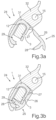
- FIG. 3 a , 3 b respective sectional views through the functional element in its position arranged on the wiper rod, wherein in FIG. 3 a the attachment device for fixing the functional element to the wiper rod is illustrated in opened state and in FIG. 3 b the attachment device is illustrated in closed position fixing the functional element to the wiper rod;
- FIG. 4 a , 4 b respective perspective views to a functional element attached to the corresponding wiper rod according to a further embodiment, in which the functional element is formed shorter and accordingly does not extend up to the spring case of the wiper arm, wherein FIG. 4 a shows the functional element with an opened attachment device and FIG. 4 b with a closed attachment device;
- FIG. 6 a , 6 b respective perspective views to a functional element attached to the corresponding wiper rod according to a further embodiment, in which the functional element is formed of two parts, which are connected to each other at a film hinge or the like and can be connected to each other and attached to the wiper rod, respectively, by folding, wherein FIG. 6 a shows the functional element before fixing to the wiper rod and FIG. 6 b shows the functional element after fixing to the wiper rod;
- FIG. 7 a partial sectional view through the functional element as well as the associated wiper rod, to which the functional element is attached, along a sectional plane, which extends in a separating plane between the two parts of the functional element, wherein in particular an attachment device becomes apparent, by means of which the functional element is secured to the wiper rod;
- FIG. 8 a - 8 c respective sectional views through the functional element according to FIGS. 6 a to 7 , wherein FIG. 8 a shows the two parts of the functional element in opened state analogously to FIG. 6 a , FIG. 8 b shows the functional element with the two parts in position arranged on the wiper rod, but not yet closed, and FIG. 8 c illustrates the two parts of the functional element after attachment to the wiper rod.
- FIGS. 1 a , 1 b and 1 c show a mounting sequence for arranging and fixing a functional element 1 , explained in more detail below, to a wiper arm 2 in a respective perspective view.
- the wiper arm 2 and the functional element 1 are first illustrated separated in exploded manner in FIG. 1 a.
- the wiper arm 2 includes a wiper rod 3 , which is angularly formed in a bend area 4 .
- the wiper rod 3 is fixedly connected to a spring case 6 on a side opposite to a free end 5 , which is at least substantially rectangularly formed in cross-section in a connection area 7 and crimped onto the wiper rod 3 also at least substantially rectangular in cross-section.
- the spring case 6 is connected to a lever element, not illustrated, of the windscreen wiper system in articulated manner via bearing openings 8 , which is occasionally also referred to as attachment part, which in turn is rotationally fixedly connected to an associated drive shaft of a drive motor.
- the wiper arm is pivotable around the axis formed by the bearing pins 8 with respect to the associated lever element against the spring force of a spring element, which in turn can be hooked in a spring receptacle 9 at the corresponding end of the wiper rod 3 , for example to press the wiper arm 2 and an associated wiper blade, respectively, against the surface of a front windscreen in the operating position.
- the functional element 1 comprises a first partial area 10 and a second partial area 11 formed integrally with it, within which a continuous receiving channel 12 for the wiper rod 3 is provided.
- the receiving channel 12 is at least substantially adapted in cross-section to the approximately rectangular cross-section of the wiper rod 3 , which has an at least substantially uniform cross-section over its entire extension. Accordingly, the receiving channel 12 also has a substantially uniform cross-section over its entire length within the functional element 1 .
- the functional element 1 can accordingly be fitted or shifted onto the wiper rod 3 from the free end 5 until an end 13 of the first partial area 10 of the functional element 1 joins to the connection area 7 of the spring case 6 in at least substantially flush manner.
- the functional element 1 is manufactured of an elastic material, for example a corresponding plastic, in the first partial area 10 —starting from the end 13 —at least over the bend area 4 .
- this soft-elastic material it is optionally also conceivable that the connection area 7 of the spring case 6 is surmounted by the end 13 of the partial area 10 of the functional element 1 in sleeve-like manner.
- the end 13 of the partial area 10 is surmounted by a conduit part 14 , via which the functional element 1 can be supplied with a windscreen cleaning liquid in a manner described in more detail below.
- at least one supply channel 15 for windscreen cleaning liquid is formed within the conduit part 14 , via which the functional element 1 can be supplied with windscreen cleaning liquid in a manner described in more detail below.
- This supply channel 15 further extends also over the partial area 10 as well as over the partial area 11 of the functional element 1 .
- a windscreen cleaning device 16 or a part of it is formed in the functional element 1 such that the wiper arm 2 is a so-called wet wiper arm in the present case.
- the windscreen to be cleaned by means of the windscreen wiper system in particular the front windscreen of the motor vehicle, can be supplied with windscreen cleaning liquid via nozzles, which are carried by the wiper arm 2 .
- the end of the conduit part 14 of the functional element 1 is connected to the windscreen cleaning system for windscreen cleaning liquid along with associated pump via a channel arrangement not further shown.
- the conduit part 14 extends on the bottom side of the wiper rod 3 further up to the interior of the spring case 6 in the present case.
- the free end 5 protrudes beyond the partial area 11 of the functional element 1 and from the receiving channel 12 , respectively.
- the windscreen cleaning device 16 integrated in the functional element 1 presently includes a channel system with respective channels integrated in the functional element 1 , which open into diverse nozzles, via which the windscreen to be cleaned and to be wiped, respectively, and the wiper blade explained in more detail below, respectively, can be supplied with windscreen cleaning liquid.
- the windscreen cleaning device 16 first includes two outer circle nozzles 17 , 18 , via which the wiper blade is supplied in the near area of its outer circle, thus that area, in which the wiper blade traverses the largest radius of its surface to be wiped.
- the outer circle nozzle 17 covers an area closer to the functional element 1 and the outer circle nozzle 18 covers an area further away from the functional element 1 near the outer circle of the corresponding wiper blade.
- the windscreen cleaning device 16 includes a plurality of presently five central nozzles 19 , which all extend at least substantially in a row along the extension direction of the functional element 1 .
- the respective nozzles 19 are accommodated in respectively associated protrusions 20 protruding from the functional element 1 and from the wiper arm 2 , respectively, towards the windscreen to be wiped and to be cleaned in a manner described below.
- the windscreen cleaning device 16 includes at least one inner circle nozzle 21 , via which the wiper blade of the wiper arm 2 is supplied with cleaning liquid in the area of its inner circle, in which the wiper blade traverses its shortest radius of the corresponding wiping surface in the wiping operation.
- all of the nozzles 17 , 18 , 19 and 21 can be adjusted such that they apply the cleaning liquid to the windscreen, in particular the front windscreen, at a corresponding distance in front of the wiper blade moving thereto upon a start movement, thus upon an upwards movement of the respective wiper arm 2 in case of a front windscreen.
- the wiper blade can also be immediately supplied with the windscreen cleaning liquid.
- the functional element 1 includes the further function of wind deflection. Accordingly, the functional element 1 is formed as a wind deflector 22 in the present case and includes a wind deflecting contour 23 on the front and top side, respectively, at least substantially facing away from the nozzles 19 as well as the wiper rod 3 to accordingly allow a particularly beneficial overflow of the air usually flowing to the respective wiper arm 2 and the corresponding wiper blade, respectively, from the front.
- the present functional element 1 is formed as a wind deflector 22 and for integration of the windscreen cleaning device 16 .
- the functional element 1 could also perform only one of these two functions.
- FIGS. 2 a to 2 c show the functional element 1 of the embodiment described in the FIGS. 1 a to 1 c in respective partial and perspective bottom views.
- the receiving channel for the wiper rod 3 is in particular apparent from FIG. 2 a , which from a third partial area 24 of the functional element 1 , which is also formed integrally with the partial areas 10 and 11 .
- the FIGS. 2 b and 2 c show the position of the functional element 1 when it is completely fitted onto the wiper rod 3 .
- the third partial area 24 of the functional element 1 covers the free end 5 of the wiper rod 3 , in particular at the front side thereof and on the bottom side thereof-related to the installation position of the wiper arm 2 .
- the wiper rod 3 is arranged recessed with respect to the partial area 24 .
- the functional element 1 is arranged secured to the wiper rod 3 of the wiper arm 2 in extension direction of the receiving channel 12 by means of an attachment device 25 in the present case.
- the securement is effected by means of a flap 26 , which is pivotably arranged on the functional element 1 via a film hinge 27 . If the flap 26 is inserted by means of a locking element 28 into a locking receptacle 29 provided hereto in the area of the receiving channel 12 , thus, the locking element 28 also engages with a groove 30 ( FIG. 1 a ) within the wiper rod 3 .
- an axial securement of the functional element 1 on the wiper rod virtually results such that the functional element 1 is correspondingly secured in position after shifting onto the wiper rod 3 .
- the attachment device 25 is again explained in its functionality in a respective sectional view of the arrangement of the functional element 1 on the wiper rod 3 .
- the axial securement of the locking element 28 on the side of the flap 26 within the locking receptacle 29 or at the groove 30 of the wiper rod 3 results.
- the functional element 1 is presently manufactured as a plastic part in a two-component method, for example a two-component injection molding method.
- the receiving channel 12 is formed by a hard component 31 in the area of the attachment device 25 .
- the respective channels carrying the cleaning liquid in the second and third partial areas 11 , 24 of the functional element 1 are formed of this hard component 31 at least in the area of the respective nozzles 17 , 18 , 19 , 21 .
- parts can also be formed by a soft component 32 of the plastic, which incidentally also form the first partial area 10 and the conduit part 14 —as already explained.
- the wind deflector contour 23 of the functional element 1 is also formed by the soft component 32 —as it is apparent from the FIGS. 3 a and 3 b .
- the components 31 , 32 are in particular formed UV-resistant to be correspondingly permanently durable.
- FIGS. 4 a and 4 b an alternative embodiment of the functional element 1 is illustrated in a respective perspective view.
- This functional element 1 is substantially identical to that according to the first described embodiment in its configuration and function such that only the differences are to be addressed below.
- This functional element 1 substantially differs in that in it the first partial area 10 of the functional element 1 , which extends between the second partial area 11 and the connection area 7 of the spring case 6 , is not provided here. Rather, the functional element 1 terminates with an end 33 at a distance before the bend area 4 and accordingly at a substantial distance before the connection area 7 of the spring case 6 .
- the conduit part 14 of the functional element 1 accordingly extends over a substantial length without additional sheathing of the wiper rod 3 below or inside it up into the spring case 6 , from where the further connection for supply with the cleaning liquid is effected.
- one or multiple respective inner circle nozzles 21 can optionally be omitted in some embodiments.
- a configuration for example arises in vehicles of the compact class, in which a relatively low windscreen surface has to be wiped and cleaned, respectively.
- the windscreen cleaning device 16 integrated in the functional element 1 has a configuration at least substantially identical to the embodiment already described in context of the FIGS. 1 a to 3 b .
- the locking element 28 is again apparent, by means of which the functional element 1 can be secured after fitting onto the wiper rod 3 .
- FIGS. 5 a and 5 b mounting of a wiper blade 34 on the corresponding free end 5 of the wiper rod 3 , which protrudes from the receiving channel 12 of the functional element 1 , is finally illustrated in a respective perspective view.
- the wiper blade 34 includes a wiper blade element 35 , to which a basic body in the form of a slider 36 is attached.
- This slider 36 is in turn connected to an adapter 37 in articulated manner such that the wiper blade element 35 with the slider 36 can be pivoted relatively to the adapter 37 to a certain extent.
- the adapter 37 includes a receptacle 38 formed at least partially open in the present case, via which the adapter 37 and thus the entire wiper blade 34 , respectively, can be fitted at the free end 5 of the wiper rod 3 .
- the receptacle 38 which is formed as a type of plug-in receptacle, is adapted in its cross-section and in its shape, respectively, to the cross-section of the wiper rod 3 .
- a locking device 39 engages, which includes a corresponding locking element both on the side of the adapter 37 and on the side of the wiper rod 3 .
- This locking device 39 can for example include a locking pin or the like on the side of the adapter 37 , which engages with a locking recess on the side of the free end 5 of the wiper rod 3 .
- the locking device 39 is detachable by means of an actuating element 40 in the form of a push button or the like, which has to be pressed towards the wiper blade element 39 in the present case.
- this actuating element 40 In its locked position, this actuating element 40 penetrates a passage opening 42 within the partial area 24 of the functional element 1 . In the locked position of the locking device 39 , thus, the actuating element 40 is at least substantially arranged within this passage opening 41 and accordingly can be actuated from the front outside to remove the wiper blade 34 from the free end 5 of the wiper rod 3 .
- FIGS. 6 a and 6 b a further, alternative embodiment of the functional element 1 is illustrated in a respective perspective view.
- This functional element 1 too is substantially identical to that according to the first described embodiment in its configuration and function such that only differences are to be addressed below.
- This functional element 1 substantially differs in that it is composed of two parts 42 , 43 , which are integrally connected to each other in the manner of a film hinge.
- a completely two-part or multi-part variant would optionally also be conceivable.
- FIGS. 8 a to 8 c which show a respective cross-sectional view through the functional element 1 and the wiper rod 3 , respectively, therein, it becomes apparent in which manner the arrangement and fixing of the two parts 42 , 43 and of the functional element 1 overall, respectively, to the wiper rod 3 are effected.
- the functional element 1 is shifted and/or fitted onto the wiper rod 3 with opened parts 42 , 43 until the wiper rod 3 —as it is in particular apparent from FIG. 8 b —is arranged in its intended receiving channel 12 , which is formed analogously to the receiving channels 12 according to the first two embodiments.
- the two parts 42 , 43 of the functional element 1 or of the wind deflector 22 can be mounted on the wiper rod 3 of the wiper arm 2 in divided state.
- the two parts 42 , 43 can then be pivoted against each other around the axis formed by the film hinge 44 or the like and joined together until the parts 42 , 43 are connected to each other by means of the attachment device 45 on the side facing away from the film hinge 44 in the present case.
- the attachment device 45 includes one or more locking elements 46 at the one part 43 , which—as it is in particular apparent from FIG. 8 c —engage with each one or more corresponding locking elements in the form of locking receptacles 47 .
- a respective securing lug 48 , 49 is arranged at both parts 42 , 43 , which—as it is apparent from FIG. 7 —engage with a groove 50 in the wiper rod 3 .
- the securing lugs 48 , 49 thus act as an axial securement of the attachment device 45 in their cooperation with the groove 50 to avoid displacement of the functional element 1 in extension direction of the wiper rod 3 .
- this functional element 1 offers the advantage that the functional element 1 can be fixed to the wiper rod 3 in simple manner even if the wiper rod 3 for example has a non-rectilinear extension or a bend area 4 .
- the functional element 1 can extend both up to the spring case 6 and to the connection area 7 thereof, respectively, and terminate at a distance to this connection area 7 .
- the two parts 42 , 43 extend beyond the bend area 4 of the wiper rod 3 up to the spring case 6 .
- the functional element 1 is formed partially of an elastic plastic component 51 and partially of a hard plastic component 52 .
- the receptacle or the receiving channel 12 is formed of the hard plastic component 52 at least in the partial area 11 , but for example also in the partial area 10 , in the present case, to thus obtain a particularly fixed and secure arrangement of the functional element 1 on the wiper rod 3 .
- the receptacle or the receiving channel 12 is divided by both parts 42 , 43 of the wind deflector 22 .
- all of the liquid-carrying components of the windscreen cleaning device 16 are again at least substantially formed of the hard plastic component 52 .
- the components of the windscreen cleaning device 16 carrying the cleaning liquid are thus particularly dimensionally stably and tightly designed.
- the windscreen cleaning device 16 is therein—as it is in particular apparent from the FIGS. 8 a to 8 c —at least substantially completely integrated in the elastic plastic component 51 .
- the wiper cleaning device 16 is additionally integrated in only one of the two parts 42 , 43 of the wind deflector 22 . This in particular has advantages with respect to the tightness since components of the two parts 42 , 43 carrying cleaning liquid do not have to be connected to each other.
- a surface 53 on its visible side is at least substantially completely formed by the elastic plastic component 51 .
- the elastic plastic component 51 is preferably formed of a UV-resistant material to be correspondingly persistent.
- the elastic plastic component 51 comprises protrusions 54 , which for example serve as dampers to protect the functional element 1 or the wind deflector 22 as well as the surface of the windscreen to be cleaned.
- a functional element 1 or a wind deflector 22 which includes at least two parts 42 , 43 , which can be mounted on the component 3 of the wiper arm 2 in divided state and joined together, whereby the wind deflector 22 can be arranged on the component 3 of the wiper arm 3 .
- this has the advantage that the wiper rod 3 or a different component of the wiper arm 2 does not have to have a constant and rectilinear extension, but that the wind deflector 22 can for example also be arranged in the bend area 4 of the wiper rod 3 .
Landscapes
- Engineering & Computer Science (AREA)
- Mechanical Engineering (AREA)
- Physics & Mathematics (AREA)
- Fluid Mechanics (AREA)
- Quality & Reliability (AREA)
- Water Supply & Treatment (AREA)
- Body Structure For Vehicles (AREA)
- Pivots And Pivotal Connections (AREA)
- Ink Jet (AREA)
- Cleaning In General (AREA)
Abstract
Description
Claims (17)
Applications Claiming Priority (3)
| Application Number | Priority Date | Filing Date | Title |
|---|---|---|---|
| DE102019110082.8A DE102019110082A1 (en) | 2019-04-16 | 2019-04-16 | Wind deflector for a windshield wiper system of a motor vehicle |
| DE102019110082.8 | 2019-04-16 | ||
| PCT/EP2020/060426 WO2020212327A1 (en) | 2019-04-16 | 2020-04-14 | Wind deflector for a windscreen wiper system of a motor vehicle |
Publications (2)
| Publication Number | Publication Date |
|---|---|
| US20230356695A1 US20230356695A1 (en) | 2023-11-09 |
| US12304432B2 true US12304432B2 (en) | 2025-05-20 |
Family
ID=70333928
Family Applications (1)
| Application Number | Title | Priority Date | Filing Date |
|---|---|---|---|
| US17/604,475 Active 2041-01-15 US12304432B2 (en) | 2019-04-16 | 2020-04-14 | Wind deflector for a windscreen wiper system of a motor vehicle |
Country Status (5)
| Country | Link |
|---|---|
| US (1) | US12304432B2 (en) |
| EP (1) | EP3956182B1 (en) |
| CN (1) | CN113874260B (en) |
| DE (1) | DE102019110082A1 (en) |
| WO (1) | WO2020212327A1 (en) |
Families Citing this family (1)
| Publication number | Priority date | Publication date | Assignee | Title |
|---|---|---|---|---|
| FR3119135B1 (en) * | 2021-01-28 | 2023-10-27 | Valeo Systemes Dessuyage | One-piece vehicle wiper system deflector |
Citations (18)
| Publication number | Priority date | Publication date | Assignee | Title |
|---|---|---|---|---|
| US2799887A (en) * | 1954-03-18 | 1957-07-23 | Earl A Nemic | Windshield wiper and signal |
| FR2109141A5 (en) | 1970-10-02 | 1972-05-26 | Baut Jacques | |
| US3793666A (en) * | 1971-12-23 | 1974-02-26 | A Wurth | Windscreen washer |
| DE7401160U (en) | 1974-01-15 | 1974-05-22 | Rau G Gmbh | Plastic pressure body for a wiper arm or a wiper blade bracket |
| DE8716154U1 (en) | 1987-01-29 | 1988-01-28 | The Anderson Company of Indiana, Michigan City, Ind. | Mounting device for a windscreen wiper |
| US4989290A (en) * | 1988-08-09 | 1991-02-05 | Mitsuba Electric Manufacturing Co., Ltd. | Wiper arm equipment |
| DE4032256A1 (en) * | 1990-10-11 | 1992-04-16 | Swf Auto Electric Gmbh | Universal holder for tubes of wiper arms - has elastically deformable section to adapt to bend in arm |
| WO1992021537A1 (en) * | 1991-05-25 | 1992-12-10 | Swf Auto-Electric Gmbh | Wiper arm, especially for motor vehicles |
| EP0565437A1 (en) | 1992-04-08 | 1993-10-13 | Valeo Systemes D'essuyage | Air deflector for a windscreenwiper with a supple detachable edge |
| KR19980018628U (en) | 1996-09-30 | 1998-07-06 | 양재신 | Integral Folding Wiper Spoiler |
| US5842251A (en) * | 1996-11-29 | 1998-12-01 | Valeo Systems D'essuyage | Automobile wiper having an improved washing liquid spray device |
| US5894626A (en) * | 1994-04-29 | 1999-04-20 | Itt Automotive Europe Gmbh | Wiper arm, especially for motor vehicles |
| DE10000382A1 (en) | 2000-01-07 | 2001-09-13 | Valeo Auto Electric Gmbh | Wiper blade assembly for cleaning vehicle windscreens, has tapered spoiler with concave profile section extending along half the length of the blade |
| EP1385722A1 (en) | 2001-04-26 | 2004-02-04 | Robert Bosch GmbH | Wiper blade for cleaning panes, in particular of a motor vehicle |
| DE102015224620A1 (en) | 2015-12-08 | 2017-06-08 | Robert Bosch Gmbh | Hose holder for a wiper arm, a wiper arm with a hose holder, as well as a method for producing such a hose holder |
| US10077028B2 (en) * | 2013-06-26 | 2018-09-18 | Robert Bosch Gmbh | Wiper arm arrangement |
| CN108749771A (en) | 2018-06-21 | 2018-11-06 | 华侨大学 | The wiper of comprehensive cleaning function can be achieved |
| FR3086618B1 (en) * | 2018-09-28 | 2021-11-26 | Bosch Gmbh Robert | Adapter unit for coupling a wiper blade to a wiper arm |
-
2019
- 2019-04-16 DE DE102019110082.8A patent/DE102019110082A1/en not_active Withdrawn
-
2020
- 2020-04-14 CN CN202080029330.7A patent/CN113874260B/en active Active
- 2020-04-14 WO PCT/EP2020/060426 patent/WO2020212327A1/en not_active Ceased
- 2020-04-14 EP EP20720386.0A patent/EP3956182B1/en active Active
- 2020-04-14 US US17/604,475 patent/US12304432B2/en active Active
Patent Citations (22)
| Publication number | Priority date | Publication date | Assignee | Title |
|---|---|---|---|---|
| US2799887A (en) * | 1954-03-18 | 1957-07-23 | Earl A Nemic | Windshield wiper and signal |
| FR2109141A5 (en) | 1970-10-02 | 1972-05-26 | Baut Jacques | |
| US3793666A (en) * | 1971-12-23 | 1974-02-26 | A Wurth | Windscreen washer |
| DE7401160U (en) | 1974-01-15 | 1974-05-22 | Rau G Gmbh | Plastic pressure body for a wiper arm or a wiper blade bracket |
| DE8716154U1 (en) | 1987-01-29 | 1988-01-28 | The Anderson Company of Indiana, Michigan City, Ind. | Mounting device for a windscreen wiper |
| US4782547A (en) | 1987-01-29 | 1988-11-08 | The Anderson Company Of Indiana | Attachment structure |
| US4989290A (en) * | 1988-08-09 | 1991-02-05 | Mitsuba Electric Manufacturing Co., Ltd. | Wiper arm equipment |
| DE4032256A1 (en) * | 1990-10-11 | 1992-04-16 | Swf Auto Electric Gmbh | Universal holder for tubes of wiper arms - has elastically deformable section to adapt to bend in arm |
| WO1992021537A1 (en) * | 1991-05-25 | 1992-12-10 | Swf Auto-Electric Gmbh | Wiper arm, especially for motor vehicles |
| EP0565437A1 (en) | 1992-04-08 | 1993-10-13 | Valeo Systemes D'essuyage | Air deflector for a windscreenwiper with a supple detachable edge |
| US5894626A (en) * | 1994-04-29 | 1999-04-20 | Itt Automotive Europe Gmbh | Wiper arm, especially for motor vehicles |
| KR19980018628U (en) | 1996-09-30 | 1998-07-06 | 양재신 | Integral Folding Wiper Spoiler |
| US5842251A (en) * | 1996-11-29 | 1998-12-01 | Valeo Systems D'essuyage | Automobile wiper having an improved washing liquid spray device |
| DE10000382A1 (en) | 2000-01-07 | 2001-09-13 | Valeo Auto Electric Gmbh | Wiper blade assembly for cleaning vehicle windscreens, has tapered spoiler with concave profile section extending along half the length of the blade |
| EP1385722A1 (en) | 2001-04-26 | 2004-02-04 | Robert Bosch GmbH | Wiper blade for cleaning panes, in particular of a motor vehicle |
| US20040098821A1 (en) * | 2001-04-26 | 2004-05-27 | Godelieve Kraemer | Wiper blade for cleaning panes, in particular of a motor vehicle |
| US8544136B2 (en) | 2001-04-26 | 2013-10-01 | Robert Bosch Gmbh | Automobile windshield wiper blade |
| US10077028B2 (en) * | 2013-06-26 | 2018-09-18 | Robert Bosch Gmbh | Wiper arm arrangement |
| DE102015224620A1 (en) | 2015-12-08 | 2017-06-08 | Robert Bosch Gmbh | Hose holder for a wiper arm, a wiper arm with a hose holder, as well as a method for producing such a hose holder |
| US10759390B2 (en) | 2015-12-08 | 2020-09-01 | Robert Bosch Gmbh | Tube holder for a wiper arm, wiper arm having a tube holder, and method for producing such a tube holder |
| CN108749771A (en) | 2018-06-21 | 2018-11-06 | 华侨大学 | The wiper of comprehensive cleaning function can be achieved |
| FR3086618B1 (en) * | 2018-09-28 | 2021-11-26 | Bosch Gmbh Robert | Adapter unit for coupling a wiper blade to a wiper arm |
Also Published As
| Publication number | Publication date |
|---|---|
| DE102019110082A1 (en) | 2020-10-22 |
| WO2020212327A1 (en) | 2020-10-22 |
| CN113874260B (en) | 2025-12-02 |
| EP3956182A1 (en) | 2022-02-23 |
| US20230356695A1 (en) | 2023-11-09 |
| CN113874260A (en) | 2021-12-31 |
| EP3956182B1 (en) | 2024-06-26 |
Similar Documents
| Publication | Publication Date | Title |
|---|---|---|
| US11731587B2 (en) | Windscreen wiper system for a motor vehicle | |
| US20220212632A1 (en) | Wind deflector for a windscreen wiper system of a motor vehicle | |
| CN107206973B (en) | Window wiper nozzle for a vehicle | |
| US9067567B2 (en) | Vehicle wiper apparatus | |
| JP4580124B2 (en) | Wiper arm | |
| US20080263806A1 (en) | Wiper Blade | |
| US8584303B2 (en) | Wiper arm for a window wiper system, window wiper system and method for installing a window wiper system | |
| US20160375865A1 (en) | Adapter for a motor vehicle windscreen wiper and assembly having such an adapter | |
| CN104080665B (en) | For cleaning the Wiper system of vehicle window | |
| US20160375874A1 (en) | Adapter for a motor vehicle windscreen wiper and assembly having such an adapter | |
| KR20130108578A (en) | Method for securing a blade onto a wiper | |
| CN104428178B (en) | Wiper blades with hydraulic connectors | |
| US12304432B2 (en) | Wind deflector for a windscreen wiper system of a motor vehicle | |
| US9221429B2 (en) | Wiper coupler assembly and wiper assembly incorporating same | |
| US11858474B2 (en) | Wind deflector for a window wiper system of a motor vehicle | |
| CN106335472B (en) | Adapter for connecting a wiper blade to a drive arm | |
| US20160304062A1 (en) | End-piece intended to be mounted on a flexible support and wiper including the end-piece and the flexible support | |
| RU2634788C1 (en) | Windscreen wiper with at least one arm of its blade and with at least one spray element | |
| CN112424033B (en) | Windshield wiper arms for cars | |
| JP2004501826A (en) | Link for windshield wiper | |
| CN106394510A (en) | Member for a system for connecting a windscreen wiper blade to multiple windscreen wiper arms | |
| US10183651B2 (en) | Wiper and Wiper assembly including such a wiper | |
| JP6437235B2 (en) | Wiper device | |
| JP2016037209A (en) | Nozzle unit |
Legal Events
| Date | Code | Title | Description |
|---|---|---|---|
| FEPP | Fee payment procedure |
Free format text: ENTITY STATUS SET TO UNDISCOUNTED (ORIGINAL EVENT CODE: BIG.); ENTITY STATUS OF PATENT OWNER: LARGE ENTITY |
|
| AS | Assignment |
Owner name: VOLKSWAGEN AKTIENGESELLSCHAFT, GERMANY Free format text: ASSIGNMENT OF ASSIGNORS INTEREST;ASSIGNORS:HAEFNER, STEPHAN;ACKERMANN, FRANK;AUCH, SVEN;AND OTHERS;SIGNING DATES FROM 20211007 TO 20211014;REEL/FRAME:057842/0871 Owner name: A. RAYMOND ET CIE, FRANCE Free format text: ASSIGNMENT OF ASSIGNORS INTEREST;ASSIGNORS:HAEFNER, STEPHAN;ACKERMANN, FRANK;AUCH, SVEN;AND OTHERS;SIGNING DATES FROM 20211007 TO 20211014;REEL/FRAME:057842/0871 Owner name: DR. ING. H.C.F. PORSCHE AG, GERMANY Free format text: ASSIGNMENT OF ASSIGNORS INTEREST;ASSIGNORS:HAEFNER, STEPHAN;ACKERMANN, FRANK;AUCH, SVEN;AND OTHERS;SIGNING DATES FROM 20211007 TO 20211014;REEL/FRAME:057842/0871 Owner name: AUDI AG, GERMANY Free format text: ASSIGNMENT OF ASSIGNORS INTEREST;ASSIGNORS:HAEFNER, STEPHAN;ACKERMANN, FRANK;AUCH, SVEN;AND OTHERS;SIGNING DATES FROM 20211007 TO 20211014;REEL/FRAME:057842/0871 |
|
| STPP | Information on status: patent application and granting procedure in general |
Free format text: NON FINAL ACTION MAILED |
|
| STPP | Information on status: patent application and granting procedure in general |
Free format text: RESPONSE TO NON-FINAL OFFICE ACTION ENTERED AND FORWARDED TO EXAMINER |
|
| STPP | Information on status: patent application and granting procedure in general |
Free format text: FINAL REJECTION MAILED |
|
| STPP | Information on status: patent application and granting procedure in general |
Free format text: RESPONSE AFTER FINAL ACTION FORWARDED TO EXAMINER |
|
| STPP | Information on status: patent application and granting procedure in general |
Free format text: ADVISORY ACTION MAILED |
|
| STPP | Information on status: patent application and granting procedure in general |
Free format text: DOCKETED NEW CASE - READY FOR EXAMINATION |
|
| STPP | Information on status: patent application and granting procedure in general |
Free format text: NON FINAL ACTION MAILED |
|
| STPP | Information on status: patent application and granting procedure in general |
Free format text: RESPONSE TO NON-FINAL OFFICE ACTION ENTERED AND FORWARDED TO EXAMINER |
|
| STPP | Information on status: patent application and granting procedure in general |
Free format text: NOTICE OF ALLOWANCE MAILED -- APPLICATION RECEIVED IN OFFICE OF PUBLICATIONS |
|
| STCF | Information on status: patent grant |
Free format text: PATENTED CASE |