US12304155B2 - Fusion structure, inflatable product having the fusion structure, manufacturing method thereof, and rapidly produced inflatable product having covering layer simultaneously positioned with inflatable body - Google Patents
Fusion structure, inflatable product having the fusion structure, manufacturing method thereof, and rapidly produced inflatable product having covering layer simultaneously positioned with inflatable body Download PDFInfo
- Publication number
- US12304155B2 US12304155B2 US16/612,353 US201816612353A US12304155B2 US 12304155 B2 US12304155 B2 US 12304155B2 US 201816612353 A US201816612353 A US 201816612353A US 12304155 B2 US12304155 B2 US 12304155B2
- Authority
- US
- United States
- Prior art keywords
- fusion
- layer
- auxiliary
- sheet
- target
- Prior art date
- Legal status (The legal status is an assumption and is not a legal conclusion. Google has not performed a legal analysis and makes no representation as to the accuracy of the status listed.)
- Active, expires
Links
Images


Classifications
-
- A—HUMAN NECESSITIES
- A47—FURNITURE; DOMESTIC ARTICLES OR APPLIANCES; COFFEE MILLS; SPICE MILLS; SUCTION CLEANERS IN GENERAL
- A47C—CHAIRS; SOFAS; BEDS
- A47C27/00—Spring, stuffed or fluid mattresses or cushions specially adapted for chairs, beds or sofas
- A47C27/08—Fluid mattresses
- A47C27/081—Fluid mattresses of pneumatic type
-
- A—HUMAN NECESSITIES
- A47—FURNITURE; DOMESTIC ARTICLES OR APPLIANCES; COFFEE MILLS; SPICE MILLS; SUCTION CLEANERS IN GENERAL
- A47C—CHAIRS; SOFAS; BEDS
- A47C27/00—Spring, stuffed or fluid mattresses or cushions specially adapted for chairs, beds or sofas
- A47C27/08—Fluid mattresses
- A47C27/087—Fluid mattresses with means for connecting opposite sides, e.g. internal ties or strips
-
- B—PERFORMING OPERATIONS; TRANSPORTING
- B29—WORKING OF PLASTICS; WORKING OF SUBSTANCES IN A PLASTIC STATE IN GENERAL
- B29C—SHAPING OR JOINING OF PLASTICS; SHAPING OF MATERIAL IN A PLASTIC STATE, NOT OTHERWISE PROVIDED FOR; AFTER-TREATMENT OF THE SHAPED PRODUCTS, e.g. REPAIRING
- B29C65/00—Joining or sealing of preformed parts, e.g. welding of plastics materials; Apparatus therefor
- B29C65/02—Joining or sealing of preformed parts, e.g. welding of plastics materials; Apparatus therefor by heating, with or without pressure
-
- B—PERFORMING OPERATIONS; TRANSPORTING
- B29—WORKING OF PLASTICS; WORKING OF SUBSTANCES IN A PLASTIC STATE IN GENERAL
- B29C—SHAPING OR JOINING OF PLASTICS; SHAPING OF MATERIAL IN A PLASTIC STATE, NOT OTHERWISE PROVIDED FOR; AFTER-TREATMENT OF THE SHAPED PRODUCTS, e.g. REPAIRING
- B29C66/00—General aspects of processes or apparatus for joining preformed parts
- B29C66/40—General aspects of joining substantially flat articles, e.g. plates, sheets or web-like materials; Making flat seams in tubular or hollow articles; Joining single elements to substantially flat surfaces
- B29C66/41—Joining substantially flat articles ; Making flat seams in tubular or hollow articles
-
- B—PERFORMING OPERATIONS; TRANSPORTING
- B29—WORKING OF PLASTICS; WORKING OF SUBSTANCES IN A PLASTIC STATE IN GENERAL
- B29C—SHAPING OR JOINING OF PLASTICS; SHAPING OF MATERIAL IN A PLASTIC STATE, NOT OTHERWISE PROVIDED FOR; AFTER-TREATMENT OF THE SHAPED PRODUCTS, e.g. REPAIRING
- B29C66/00—General aspects of processes or apparatus for joining preformed parts
- B29C66/70—General aspects of processes or apparatus for joining preformed parts characterised by the composition, physical properties or the structure of the material of the parts to be joined; Joining with non-plastics material
- B29C66/72—General aspects of processes or apparatus for joining preformed parts characterised by the composition, physical properties or the structure of the material of the parts to be joined; Joining with non-plastics material characterised by the structure of the material of the parts to be joined
- B29C66/723—General aspects of processes or apparatus for joining preformed parts characterised by the composition, physical properties or the structure of the material of the parts to be joined; Joining with non-plastics material characterised by the structure of the material of the parts to be joined being multi-layered
- B29C66/7232—General aspects of processes or apparatus for joining preformed parts characterised by the composition, physical properties or the structure of the material of the parts to be joined; Joining with non-plastics material characterised by the structure of the material of the parts to be joined being multi-layered comprising a non-plastics layer
-
- B—PERFORMING OPERATIONS; TRANSPORTING
- B29—WORKING OF PLASTICS; WORKING OF SUBSTANCES IN A PLASTIC STATE IN GENERAL
- B29D—PRODUCING PARTICULAR ARTICLES FROM PLASTICS OR FROM SUBSTANCES IN A PLASTIC STATE
- B29D22/00—Producing hollow articles
- B29D22/02—Inflatable articles
-
- B—PERFORMING OPERATIONS; TRANSPORTING
- B32—LAYERED PRODUCTS
- B32B—LAYERED PRODUCTS, i.e. PRODUCTS BUILT-UP OF STRATA OF FLAT OR NON-FLAT, e.g. CELLULAR OR HONEYCOMB, FORM
- B32B27/00—Layered products comprising a layer of synthetic resin
- B32B27/12—Layered products comprising a layer of synthetic resin next to a fibrous or filamentary layer
-
- B—PERFORMING OPERATIONS; TRANSPORTING
- B32—LAYERED PRODUCTS
- B32B—LAYERED PRODUCTS, i.e. PRODUCTS BUILT-UP OF STRATA OF FLAT OR NON-FLAT, e.g. CELLULAR OR HONEYCOMB, FORM
- B32B3/00—Layered products comprising a layer with external or internal discontinuities or unevennesses, or a layer of non-planar shape; Layered products comprising a layer having particular features of form
- B32B3/26—Layered products comprising a layer with external or internal discontinuities or unevennesses, or a layer of non-planar shape; Layered products comprising a layer having particular features of form characterised by a particular shape of the outline of the cross-section of a continuous layer; characterised by a layer with cavities or internal voids ; characterised by an apertured layer
- B32B3/266—Layered products comprising a layer with external or internal discontinuities or unevennesses, or a layer of non-planar shape; Layered products comprising a layer having particular features of form characterised by a particular shape of the outline of the cross-section of a continuous layer; characterised by a layer with cavities or internal voids ; characterised by an apertured layer characterised by an apertured layer, the apertures going through the whole thickness of the layer, e.g. expanded metal, perforated layer, slit layer regular cells B32B3/12
-
- B—PERFORMING OPERATIONS; TRANSPORTING
- B32—LAYERED PRODUCTS
- B32B—LAYERED PRODUCTS, i.e. PRODUCTS BUILT-UP OF STRATA OF FLAT OR NON-FLAT, e.g. CELLULAR OR HONEYCOMB, FORM
- B32B5/00—Layered products characterised by the non- homogeneity or physical structure, i.e. comprising a fibrous, filamentary, particulate or foam layer; Layered products characterised by having a layer differing constitutionally or physically in different parts
- B32B5/02—Layered products characterised by the non- homogeneity or physical structure, i.e. comprising a fibrous, filamentary, particulate or foam layer; Layered products characterised by having a layer differing constitutionally or physically in different parts characterised by structural features of a fibrous or filamentary layer
-
- B—PERFORMING OPERATIONS; TRANSPORTING
- B29—WORKING OF PLASTICS; WORKING OF SUBSTANCES IN A PLASTIC STATE IN GENERAL
- B29C—SHAPING OR JOINING OF PLASTICS; SHAPING OF MATERIAL IN A PLASTIC STATE, NOT OTHERWISE PROVIDED FOR; AFTER-TREATMENT OF THE SHAPED PRODUCTS, e.g. REPAIRING
- B29C65/00—Joining or sealing of preformed parts, e.g. welding of plastics materials; Apparatus therefor
- B29C65/48—Joining or sealing of preformed parts, e.g. welding of plastics materials; Apparatus therefor using adhesives, i.e. using supplementary joining material; solvent bonding
- B29C65/4805—Joining or sealing of preformed parts, e.g. welding of plastics materials; Apparatus therefor using adhesives, i.e. using supplementary joining material; solvent bonding characterised by the type of adhesives
- B29C65/481—Non-reactive adhesives, e.g. physically hardening adhesives
- B29C65/4815—Hot melt adhesives, e.g. thermoplastic adhesives
-
- B—PERFORMING OPERATIONS; TRANSPORTING
- B29—WORKING OF PLASTICS; WORKING OF SUBSTANCES IN A PLASTIC STATE IN GENERAL
- B29C—SHAPING OR JOINING OF PLASTICS; SHAPING OF MATERIAL IN A PLASTIC STATE, NOT OTHERWISE PROVIDED FOR; AFTER-TREATMENT OF THE SHAPED PRODUCTS, e.g. REPAIRING
- B29C65/00—Joining or sealing of preformed parts, e.g. welding of plastics materials; Apparatus therefor
- B29C65/48—Joining or sealing of preformed parts, e.g. welding of plastics materials; Apparatus therefor using adhesives, i.e. using supplementary joining material; solvent bonding
- B29C65/50—Joining or sealing of preformed parts, e.g. welding of plastics materials; Apparatus therefor using adhesives, i.e. using supplementary joining material; solvent bonding using adhesive tape, e.g. thermoplastic tape; using threads or the like
- B29C65/5057—Joining or sealing of preformed parts, e.g. welding of plastics materials; Apparatus therefor using adhesives, i.e. using supplementary joining material; solvent bonding using adhesive tape, e.g. thermoplastic tape; using threads or the like positioned between the surfaces to be joined
-
- B—PERFORMING OPERATIONS; TRANSPORTING
- B29—WORKING OF PLASTICS; WORKING OF SUBSTANCES IN A PLASTIC STATE IN GENERAL
- B29C—SHAPING OR JOINING OF PLASTICS; SHAPING OF MATERIAL IN A PLASTIC STATE, NOT OTHERWISE PROVIDED FOR; AFTER-TREATMENT OF THE SHAPED PRODUCTS, e.g. REPAIRING
- B29C65/00—Joining or sealing of preformed parts, e.g. welding of plastics materials; Apparatus therefor
- B29C65/48—Joining or sealing of preformed parts, e.g. welding of plastics materials; Apparatus therefor using adhesives, i.e. using supplementary joining material; solvent bonding
- B29C65/50—Joining or sealing of preformed parts, e.g. welding of plastics materials; Apparatus therefor using adhesives, i.e. using supplementary joining material; solvent bonding using adhesive tape, e.g. thermoplastic tape; using threads or the like
- B29C65/5064—Joining or sealing of preformed parts, e.g. welding of plastics materials; Apparatus therefor using adhesives, i.e. using supplementary joining material; solvent bonding using adhesive tape, e.g. thermoplastic tape; using threads or the like of particular form, e.g. being C-shaped, T-shaped
- B29C65/5078—Joining or sealing of preformed parts, e.g. welding of plastics materials; Apparatus therefor using adhesives, i.e. using supplementary joining material; solvent bonding using adhesive tape, e.g. thermoplastic tape; using threads or the like of particular form, e.g. being C-shaped, T-shaped and being composed by several elements
-
- B—PERFORMING OPERATIONS; TRANSPORTING
- B29—WORKING OF PLASTICS; WORKING OF SUBSTANCES IN A PLASTIC STATE IN GENERAL
- B29C—SHAPING OR JOINING OF PLASTICS; SHAPING OF MATERIAL IN A PLASTIC STATE, NOT OTHERWISE PROVIDED FOR; AFTER-TREATMENT OF THE SHAPED PRODUCTS, e.g. REPAIRING
- B29C65/00—Joining or sealing of preformed parts, e.g. welding of plastics materials; Apparatus therefor
- B29C65/56—Joining or sealing of preformed parts, e.g. welding of plastics materials; Apparatus therefor using mechanical means or mechanical connections, e.g. form-fits
- B29C65/62—Stitching
-
- B—PERFORMING OPERATIONS; TRANSPORTING
- B29—WORKING OF PLASTICS; WORKING OF SUBSTANCES IN A PLASTIC STATE IN GENERAL
- B29C—SHAPING OR JOINING OF PLASTICS; SHAPING OF MATERIAL IN A PLASTIC STATE, NOT OTHERWISE PROVIDED FOR; AFTER-TREATMENT OF THE SHAPED PRODUCTS, e.g. REPAIRING
- B29C66/00—General aspects of processes or apparatus for joining preformed parts
- B29C66/01—General aspects dealing with the joint area or with the area to be joined
- B29C66/05—Particular design of joint configurations
- B29C66/10—Particular design of joint configurations particular design of the joint cross-sections
- B29C66/11—Joint cross-sections comprising a single joint-segment, i.e. one of the parts to be joined comprising a single joint-segment in the joint cross-section
- B29C66/112—Single lapped joints
-
- B—PERFORMING OPERATIONS; TRANSPORTING
- B29—WORKING OF PLASTICS; WORKING OF SUBSTANCES IN A PLASTIC STATE IN GENERAL
- B29C—SHAPING OR JOINING OF PLASTICS; SHAPING OF MATERIAL IN A PLASTIC STATE, NOT OTHERWISE PROVIDED FOR; AFTER-TREATMENT OF THE SHAPED PRODUCTS, e.g. REPAIRING
- B29C66/00—General aspects of processes or apparatus for joining preformed parts
- B29C66/01—General aspects dealing with the joint area or with the area to be joined
- B29C66/05—Particular design of joint configurations
- B29C66/10—Particular design of joint configurations particular design of the joint cross-sections
- B29C66/13—Single flanged joints; Fin-type joints; Single hem joints; Edge joints; Interpenetrating fingered joints; Other specific particular designs of joint cross-sections not provided for in groups B29C66/11 - B29C66/12
- B29C66/131—Single flanged joints, i.e. one of the parts to be joined being rigid and flanged in the joint area
- B29C66/1312—Single flange to flange joints, the parts to be joined being rigid
-
- B—PERFORMING OPERATIONS; TRANSPORTING
- B29—WORKING OF PLASTICS; WORKING OF SUBSTANCES IN A PLASTIC STATE IN GENERAL
- B29C—SHAPING OR JOINING OF PLASTICS; SHAPING OF MATERIAL IN A PLASTIC STATE, NOT OTHERWISE PROVIDED FOR; AFTER-TREATMENT OF THE SHAPED PRODUCTS, e.g. REPAIRING
- B29C66/00—General aspects of processes or apparatus for joining preformed parts
- B29C66/40—General aspects of joining substantially flat articles, e.g. plates, sheets or web-like materials; Making flat seams in tubular or hollow articles; Joining single elements to substantially flat surfaces
- B29C66/41—Joining substantially flat articles ; Making flat seams in tubular or hollow articles
- B29C66/43—Joining a relatively small portion of the surface of said articles
- B29C66/432—Joining a relatively small portion of the surface of said articles for making tubular articles or closed loops, e.g. by joining several sheets ; for making hollow articles or hollow preforms
- B29C66/4322—Joining a relatively small portion of the surface of said articles for making tubular articles or closed loops, e.g. by joining several sheets ; for making hollow articles or hollow preforms by joining a single sheet to itself
-
- B—PERFORMING OPERATIONS; TRANSPORTING
- B29—WORKING OF PLASTICS; WORKING OF SUBSTANCES IN A PLASTIC STATE IN GENERAL
- B29C—SHAPING OR JOINING OF PLASTICS; SHAPING OF MATERIAL IN A PLASTIC STATE, NOT OTHERWISE PROVIDED FOR; AFTER-TREATMENT OF THE SHAPED PRODUCTS, e.g. REPAIRING
- B29C66/00—General aspects of processes or apparatus for joining preformed parts
- B29C66/70—General aspects of processes or apparatus for joining preformed parts characterised by the composition, physical properties or the structure of the material of the parts to be joined; Joining with non-plastics material
- B29C66/71—General aspects of processes or apparatus for joining preformed parts characterised by the composition, physical properties or the structure of the material of the parts to be joined; Joining with non-plastics material characterised by the composition of the plastics material of the parts to be joined
-
- B—PERFORMING OPERATIONS; TRANSPORTING
- B29—WORKING OF PLASTICS; WORKING OF SUBSTANCES IN A PLASTIC STATE IN GENERAL
- B29C—SHAPING OR JOINING OF PLASTICS; SHAPING OF MATERIAL IN A PLASTIC STATE, NOT OTHERWISE PROVIDED FOR; AFTER-TREATMENT OF THE SHAPED PRODUCTS, e.g. REPAIRING
- B29C66/00—General aspects of processes or apparatus for joining preformed parts
- B29C66/70—General aspects of processes or apparatus for joining preformed parts characterised by the composition, physical properties or the structure of the material of the parts to be joined; Joining with non-plastics material
- B29C66/72—General aspects of processes or apparatus for joining preformed parts characterised by the composition, physical properties or the structure of the material of the parts to be joined; Joining with non-plastics material characterised by the structure of the material of the parts to be joined
- B29C66/729—Textile or other fibrous material made from plastics
-
- B—PERFORMING OPERATIONS; TRANSPORTING
- B29—WORKING OF PLASTICS; WORKING OF SUBSTANCES IN A PLASTIC STATE IN GENERAL
- B29C—SHAPING OR JOINING OF PLASTICS; SHAPING OF MATERIAL IN A PLASTIC STATE, NOT OTHERWISE PROVIDED FOR; AFTER-TREATMENT OF THE SHAPED PRODUCTS, e.g. REPAIRING
- B29C66/00—General aspects of processes or apparatus for joining preformed parts
- B29C66/70—General aspects of processes or apparatus for joining preformed parts characterised by the composition, physical properties or the structure of the material of the parts to be joined; Joining with non-plastics material
- B29C66/73—General aspects of processes or apparatus for joining preformed parts characterised by the composition, physical properties or the structure of the material of the parts to be joined; Joining with non-plastics material characterised by the intensive physical properties of the material of the parts to be joined, by the optical properties of the material of the parts to be joined, by the extensive physical properties of the parts to be joined, by the state of the material of the parts to be joined or by the material of the parts to be joined being a thermoplastic or a thermoset
- B29C66/731—General aspects of processes or apparatus for joining preformed parts characterised by the composition, physical properties or the structure of the material of the parts to be joined; Joining with non-plastics material characterised by the intensive physical properties of the material of the parts to be joined, by the optical properties of the material of the parts to be joined, by the extensive physical properties of the parts to be joined, by the state of the material of the parts to be joined or by the material of the parts to be joined being a thermoplastic or a thermoset characterised by the intensive physical properties of the material of the parts to be joined
- B29C66/7318—Permeability to gases or liquids
- B29C66/73185—Permeability to gases or liquids non-permeable
- B29C66/73186—Permeability to gases or liquids non-permeable to gases
-
- B—PERFORMING OPERATIONS; TRANSPORTING
- B29—WORKING OF PLASTICS; WORKING OF SUBSTANCES IN A PLASTIC STATE IN GENERAL
- B29C—SHAPING OR JOINING OF PLASTICS; SHAPING OF MATERIAL IN A PLASTIC STATE, NOT OTHERWISE PROVIDED FOR; AFTER-TREATMENT OF THE SHAPED PRODUCTS, e.g. REPAIRING
- B29C66/00—General aspects of processes or apparatus for joining preformed parts
- B29C66/70—General aspects of processes or apparatus for joining preformed parts characterised by the composition, physical properties or the structure of the material of the parts to be joined; Joining with non-plastics material
- B29C66/73—General aspects of processes or apparatus for joining preformed parts characterised by the composition, physical properties or the structure of the material of the parts to be joined; Joining with non-plastics material characterised by the intensive physical properties of the material of the parts to be joined, by the optical properties of the material of the parts to be joined, by the extensive physical properties of the parts to be joined, by the state of the material of the parts to be joined or by the material of the parts to be joined being a thermoplastic or a thermoset
- B29C66/739—General aspects of processes or apparatus for joining preformed parts characterised by the composition, physical properties or the structure of the material of the parts to be joined; Joining with non-plastics material characterised by the intensive physical properties of the material of the parts to be joined, by the optical properties of the material of the parts to be joined, by the extensive physical properties of the parts to be joined, by the state of the material of the parts to be joined or by the material of the parts to be joined being a thermoplastic or a thermoset characterised by the material of the parts to be joined being a thermoplastic or a thermoset
- B29C66/7392—General aspects of processes or apparatus for joining preformed parts characterised by the composition, physical properties or the structure of the material of the parts to be joined; Joining with non-plastics material characterised by the intensive physical properties of the material of the parts to be joined, by the optical properties of the material of the parts to be joined, by the extensive physical properties of the parts to be joined, by the state of the material of the parts to be joined or by the material of the parts to be joined being a thermoplastic or a thermoset characterised by the material of the parts to be joined being a thermoplastic or a thermoset characterised by the material of at least one of the parts being a thermoplastic
- B29C66/73921—General aspects of processes or apparatus for joining preformed parts characterised by the composition, physical properties or the structure of the material of the parts to be joined; Joining with non-plastics material characterised by the intensive physical properties of the material of the parts to be joined, by the optical properties of the material of the parts to be joined, by the extensive physical properties of the parts to be joined, by the state of the material of the parts to be joined or by the material of the parts to be joined being a thermoplastic or a thermoset characterised by the material of the parts to be joined being a thermoplastic or a thermoset characterised by the material of at least one of the parts being a thermoplastic characterised by the materials of both parts being thermoplastics
-
- B—PERFORMING OPERATIONS; TRANSPORTING
- B29—WORKING OF PLASTICS; WORKING OF SUBSTANCES IN A PLASTIC STATE IN GENERAL
- B29L—INDEXING SCHEME ASSOCIATED WITH SUBCLASS B29C, RELATING TO PARTICULAR ARTICLES
- B29L2022/00—Hollow articles
- B29L2022/02—Inflatable articles
-
- B—PERFORMING OPERATIONS; TRANSPORTING
- B32—LAYERED PRODUCTS
- B32B—LAYERED PRODUCTS, i.e. PRODUCTS BUILT-UP OF STRATA OF FLAT OR NON-FLAT, e.g. CELLULAR OR HONEYCOMB, FORM
- B32B7/00—Layered products characterised by the relation between layers; Layered products characterised by the relative orientation of features between layers, or by the relative values of a measurable parameter between layers, i.e. products comprising layers having different physical, chemical or physicochemical properties; Layered products characterised by the interconnection of layers
- B32B7/04—Interconnection of layers
- B32B7/08—Interconnection of layers by mechanical means
- B32B7/09—Interconnection of layers by mechanical means by stitching, needling or sewing
-
- B—PERFORMING OPERATIONS; TRANSPORTING
- B32—LAYERED PRODUCTS
- B32B—LAYERED PRODUCTS, i.e. PRODUCTS BUILT-UP OF STRATA OF FLAT OR NON-FLAT, e.g. CELLULAR OR HONEYCOMB, FORM
- B32B7/00—Layered products characterised by the relation between layers; Layered products characterised by the relative orientation of features between layers, or by the relative values of a measurable parameter between layers, i.e. products comprising layers having different physical, chemical or physicochemical properties; Layered products characterised by the interconnection of layers
- B32B7/04—Interconnection of layers
- B32B7/12—Interconnection of layers using interposed adhesives or interposed materials with bonding properties
-
- Y—GENERAL TAGGING OF NEW TECHNOLOGICAL DEVELOPMENTS; GENERAL TAGGING OF CROSS-SECTIONAL TECHNOLOGIES SPANNING OVER SEVERAL SECTIONS OF THE IPC; TECHNICAL SUBJECTS COVERED BY FORMER USPC CROSS-REFERENCE ART COLLECTIONS [XRACs] AND DIGESTS
- Y10—TECHNICAL SUBJECTS COVERED BY FORMER USPC
- Y10T—TECHNICAL SUBJECTS COVERED BY FORMER US CLASSIFICATION
- Y10T428/00—Stock material or miscellaneous articles
- Y10T428/13—Hollow or container type article [e.g., tube, vase, etc.]
- Y10T428/1352—Polymer or resin containing [i.e., natural or synthetic]
- Y10T428/1362—Textile, fabric, cloth, or pile containing [e.g., web, net, woven, knitted, mesh, nonwoven, matted, etc.]
- Y10T428/1366—Textile, fabric, cloth, or pile is sandwiched between two distinct layers of material unlike the textile, fabric, cloth, or pile layer
Definitions
- the invention relates to an inflatable product, and more particularly to a fusion structure, an inflatable product having the fusion structure, a manufacturing method thereof, and a rapidly produced inflatable product having a covering layer simultaneously positioned with an inflatable body.
- An inflatable product is lightweight, easy to store and portable. Therefore, the application of an inflatable product is wide (not only outdoor products and toys, but also household products can be inflatable products). However, the user can seldom expect a good durability of the inflatable product since an inflatable product is mostly manufactured by way of fusion. Damage to the inflatable product generally occurs at the fusion location, except that the inflatable product is cut or pierced. In order to improve the durability, resistance of the inflatable product to rupture in the fusion zone must be enhanced. Further, cutting or piercing the inflatable product becomes easier when the inflatable product bears a great pressure. Therefore, how an inflatable product is improved is a significant issue.
- the invention provides a fusion structure, an inflatable product having the fusion structure, a manufacturing method thereof, and a rapidly produced inflatable product having a covering layer simultaneously positioned with an inflatable body.
- the invention is simple in structure and is convenient to use. Further, the invention is able to greatly enhance the resistance of the inflatable product to rupture in the fusion zone, to increase stability of use of the inflatable product, to reduce weight of the inflatable product, and to reduce the cost.
- the invention provides the following technical solutions:
- a fusion structure for an inflatable product includes at least one fusion unit, and the fusion unit includes a target fusion layer, at least one first fusion reinforcement layer and at least one first auxiliary fusion layer which are fused together.
- the fusion reinforcement layer and the auxiliary fusion layer are alternately disposed at a side of the target fusion layer, while outermost layers of two sides of the fusion unit are the target fusion layer and the auxiliary fusion layer.
- the fusion reinforcement layer and the auxiliary fusion layer are alternately disposed at two sides of the target fusion layer, while outermost layers of two sides of the fusion unit are the auxiliary fusion layers.
- a material of which the target fusion layer is made is the same as or compatible with a material of which the auxiliary fusion layer is made.
- the fusion structure includes a fusion unit, the fusion unit comprises a target fusion layer, a first fusion reinforcement layer and a first auxiliary fusion layer which are sequentially arranged, and the target fusion layer, the first fusion reinforcement layer and the first auxiliary fusion layer are simultaneously connected by fusion.
- the fusion structure includes a fusion unit, the fusion unit includes a target fusion layer, a second auxiliary fusion layer, a first fusion reinforcement layer and a first auxiliary fusion layer which are sequentially arranged, and the target fusion layer, the second auxiliary fusion layer, the first fusion reinforcement layer and the first auxiliary fusion layer are simultaneously connected by fusion.
- the fusion structure of this form is formed by additionally providing the second auxiliary fusion layer between the target fusion layer and the first fusion reinforcement layer which are based on the fusion structure of the first form. Because the second auxiliary fusion layer is provided, the fusion structure of this form is several times higher than the fusion structure of the first form in strength.
- the fusion structure includes a fusion unit, the fusion unit includes a target fusion layer, a second auxiliary fusion layer, a first fusion reinforcement layer and a first auxiliary fusion layer which are sequentially arranged, a periphery of the second auxiliary fusion layer is connected to the target fusion layer by a first fusion, the first fusion reinforcement layer and the first auxiliary fusion layer are connected to the second auxiliary fusion layer and the target fusion layer by a second fusion, and the fusion portions formed by the first fusion and the second fusion are not overlapped.
- the fusion structure of this form is similar to that of the second form in structure, and the difference therebetween is that the fusion structure of this form is formed by fusion twice.
- the first fusion is used for connecting the periphery of the second auxiliary fusion layer and the target fusion layer together, while the second fusion is used for connecting the first fusion reinforcement layer, the first auxiliary fusion layer, the second auxiliary fusion layer and the target fusion layer.
- the fusion structure includes a fusion unit, the fusion unit includes a target fusion layer, a second auxiliary fusion layer, a first fusion reinforcement layer and a first auxiliary fusion layer which are sequentially arranged, the second auxiliary fusion layer is connected to the target fusion layer by a first fusion, the first fusion reinforcement layer and the first auxiliary fusion layer are connected to the second auxiliary fusion layer and the target fusion layer by a second fusion, the fusion portion formed by the first fusion is greater than that formed by the second fusion in area, and the fusion portion formed by the second fusion does not extend beyond that formed by the first fusion.
- the fusion structure of this form is the same as the fusion structure of the third form in structure, times of fusion and sequence of fusion, and the difference therebetween is that in the fusion structure of the third form, the fusion portions formed by the first fusion and the second fusion are not overlapped while in the fusion structure of this form, the fusion portion formed by the first fusion is greater than that formed by the second fusion in area, and the fusion portion formed by the second fusion does not extend beyond that formed by the first fusion.
- the fusion structure includes a fusion unit, the fusion unit includes a target fusion layer, a second fusion reinforcement layer, a second auxiliary fusion layer, a first fusion reinforcement layer and a first auxiliary fusion layer which are sequentially arranged, the second fusion reinforcement layer and the second auxiliary fusion layer are connected to the target fusion layer by a first fusion, the first fusion reinforcement layer and the first auxiliary fusion layer are connected to the second fusion reinforcement layer, the second auxiliary fusion layer and the target fusion layer by a second fusion, the fusion portion formed by the first fusion is greater than that formed by the second fusion in area, and the fusion portion formed by the second fusion does not extend beyond that formed by the first fusion.
- the fusion structure of this form is formed by additionally providing the second fusion reinforcement layer between the target fusion layer and the second auxiliary fusion layer based on the fusion structure of the fourth form. Because the second fusion reinforcement layer is provided, the fusion structure of this form is at least five times higher than the fusion structure of the fourth form in strength.
- the fusion structure includes a fusion unit, and the fusion unit includes a third auxiliary fusion layer, a third fusion reinforcement layer, a target fusion layer, a second auxiliary fusion layer, a first fusion reinforcement layer and a first auxiliary fusion layer which are sequentially arranged.
- the third auxiliary fusion layer, the third fusion reinforcement layer and the second auxiliary fusion layer are connected to the target fusion layer by a first fusion
- the first fusion reinforcement layer and the first auxiliary fusion layer are connected to the third auxiliary fusion layer
- the third fusion reinforcement layer, the second auxiliary fusion layer and the target fusion layer by a second fusion
- the fusion portion formed by the first fusion is greater than that formed by the second fusion in area
- the fusion portion formed by the second fusion does not extend beyond that formed by the first fusion.
- the fusion structure includes a first fusion unit and a second fusion unit.
- the first fusion unit includes a target fusion layer, a first fusion reinforcement layer and a first auxiliary fusion layer which are sequentially arranged.
- the target fusion layer, the first fusion reinforcement layer and the first auxiliary fusion layer are connected by a first fusion.
- the second fusion unit is the same as the first fusion unit in structure.
- the first fusion unit and the second fusion unit are connected by a second fusion.
- the first auxiliary fusion layer of the first fusion unit is attached to the first auxiliary fusion layer of the second fusion unit.
- the fusion portion formed by the first fusion is greater than that formed by the second fusion in area.
- the fusion portion formed by the second fusion does not extend beyond the fusion portion formed by the first fusion.
- the fusion structure of this form is formed by two fusion structures of the first form fused together.
- the fusion structure of this form has the greatest strength among the above-described fusion structures.
- the invention further provides various inflatable products including the above-described fusion structures, described as follows.
- an inflatable product in a first form, includes a top sheet and a bottom sheet, and peripheries of the top sheet and the bottom sheet are connected by any of the fusion structures of the first, second, third, fourth, fifth and sixth forms.
- An air chamber is formed between the top sheet and the bottom sheet.
- the top sheet is the target fusion layer of the fusion structure
- the bottom sheet is the first auxiliary fusion layer of the fusion structure.
- an inflatable product in a second form, includes a top sheet and a bottom sheet, and peripheries of the top sheet and the bottom sheet are connected by the fusion structure of the seventh form.
- An air chamber is formed between the top sheet and the bottom sheet.
- the top sheet is the target fusion layer of the first fusion unit
- the bottom sheet is the target fusion layer of the second fusion unit.
- an inflatable product in a third form, includes a top sheet and a bottom sheet, and peripheries of the top sheet and the bottom sheet are directly fused.
- a plurality of linear fusion sites formed by any of the fusion structures of the first, second, third, fourth, fifth and sixth forms are provided between the top sheet and the bottom sheet.
- the fusion sites are arranged to form a plurality of spaces between the top sheet and the bottom sheet into air chambers with a predetermined shape.
- the top sheet is the target fusion layer of the fusion structure
- the bottom sheet is the first auxiliary fusion layer of the fusion structure.
- an inflatable product in a fourth form, includes a top sheet and a bottom sheet, and peripheries of the top sheet and the bottom sheet are directly fused.
- a plurality of linear fusion sites which are formed by the fusion structure of the seventh form are provided between the top sheet and the bottom sheet.
- the fusion sites are arranged to form a plurality of spaces between the top sheet and the bottom sheet into air chambers with a predetermined shape.
- the top sheet is the target fusion layer of the first fusion unit
- the bottom sheet is the first auxiliary fusion layer of the second fusion unit.
- an inflatable product in a fifth form, includes a top sheet, a plurality of tensioning strips and a bottom sheet. Peripheries of the top sheet and the bottom sheet are directly fused, and the tensioning strips are connected to inner surfaces of the top sheet and the bottom sheet by any of the fusion structures of the first, second, third, fourth, fifth and sixth forms.
- the top sheet and the bottom sheet are the target fusion layer of the fusion structure, and the tensioning strips are the first fusion reinforcement layer of the fusion structure.
- an inflatable product in a sixth form, includes a top sheet, a periphery sheet, a plurality of tensioning strips and a bottom sheet. Two sides of the periphery sheet are directly connected to peripheries of the top sheet and the bottom sheet by ww forming an air chamber, and the tensioning strips are connected to inner surfaces of the top sheet and the bottom sheet by any of the fusion structures of the first, second, third, fourth, fifth and sixth forms.
- the top sheet and the bottom sheet are the target fusion layer of the fusion structure, and the tensioning strips are the first fusion reinforcement layer of the fusion structure.
- an inflatable product in a seventh form, includes a top sheet, a periphery sheet, a plurality of tensioning strips and a bottom sheet. Two sides of the periphery sheet are connected to peripheries of the top sheet and the bottom sheet by any of the fusion structures of the first, second, third, fourth, fifth and sixth forms for forming an air chamber.
- the top sheet and the bottom sheet are the target fusion layer of the fusion structure, and the periphery sheet is the first auxiliary fusion layer of the fusion structure.
- the tensioning strips are connected to inner surfaces of the top sheet and the bottom sheet by fusion.
- an inflatable product in an eighth form, includes a top sheet, a periphery sheet, a plurality of tensioning strips and a bottom sheet. Two sides of the periphery sheet are connected to peripheries of the top sheet and the bottom sheet by the fusion structure of the seventh form for forming an air chamber.
- the top sheet and the bottom sheet are the target fusion layer of the first fusion unit of the fusion structure, and the periphery sheet is the target fusion layer of the second fusion unit of the fusion structure.
- the tensioning strips are connected to inner surfaces of the top sheet and the bottom sheet by fusion.
- the tensioning strips of the inflatable products of the third and fourth forms can be classified into two categories according to the structure thereof and the fusion way that the tensioning strips are connected to the inner surfaces of the top sheet and the bottom sheet.
- a first category is that the tensioning strips are connected to the inner surfaces of the top sheet and the bottom sheet by any of the fusion structures of the first, second, third, fourth, fifth and sixth forms.
- the top sheet and the bottom sheet are the target fusion layer of the fusion structure, and the tensioning strips are the first fusion reinforcement layer of the fusion structure.
- a second category is that each of the tensioning strips includes a strip body, and the strip body is fused with the inner surfaces of the top sheet and the bottom sheet at a location where the first auxiliary fusion piece and the second auxiliary fusion piece are provided to hold and fuse with the strip body.
- the strip body is made of a flexible anti-stretch material having a plurality of through holes, and the strip body is a mesh fabric.
- the first auxiliary fusion piece and the second auxiliary fusion piece are made of the same material as the auxiliary fusion layer of the above-described fusion structure. Alternatively, the first auxiliary fusion piece or the second auxiliary fusion piece is fixed to a side of the strip body.
- tensioning strips are arranged between the top sheet and the bottom sheet in a serration pattern, and most of the teeth of the serration pattern are trapezoidal or triangular.
- the inner surfaces of the top sheet and the bottom sheet can be directly connected to the tensioning strips by fusion.
- auxiliary structures can be provided at the locations where the inner surfaces of the top sheet and the bottom sheet are connected to the tensioning strips.
- a first auxiliary structure is a third auxiliary fusion piece which is provided at the location where at least one of the outer surfaces and the inner surfaces of the top sheet and the bottom sheet fuses with the tensioning strips.
- a second auxiliary structure is a first auxiliary reinforcement piece and a third auxiliary fusion piece which are provided at the location where at least one of the outer surfaces and inner surfaces of the top sheet and the bottom sheet fuses with the tensioning strips.
- the first auxiliary reinforcement piece is attached to at least one of the outer surfaces and the inner surfaces of the top sheet and the bottom sheet, and the third auxiliary fusion piece is placed over the first auxiliary reinforcement piece.
- the auxiliary structure can directly fuse with at least one of the outer surfaces and the inner surfaces of the top sheet and the bottom sheet, and then the tensioning strips are connected thereto by fusion.
- the auxiliary structure is kept in position and then the tensioning strips are fused with the auxiliary structure and at least one of the outer surfaces and the inner surfaces of the top sheet and the bottom sheet.
- a third auxiliary structure is a fiber glue layer which has a plurality of through holes and is applied to the location where at least one of outer surfaces and the inner surfaces of the top sheet and the bottom sheet fuses with the tensioning strips.
- the third auxiliary fusion piece is made of a material which is the same as or compatible with the auxiliary fusion layer of the above-described fusion structure.
- the first auxiliary reinforcement piece is made of a material which is the same as or compatible with the fusion reinforcement layer of the above-described fusion structure.
- a thickness of the top sheet and the bottom sheet without the fusion structure is equal to or is smaller than one-third of a thickness of the top sheet and the bottom sheet with the fusion structure which is formed by including the auxiliary fusion layer but excluding the fusion reinforcement layer.
- the fusion structure can greatly enhance the ability of the inflatable product to resist stretch at the fusion locations. Thus, there is no need to thicken the top sheet and the bottom sheet of the inflatable product. Also, the cost and the weight of the inflatable product can be decreased.
- the invention further provides a method for manufacturing the tensioning strips of the second category described above, wherein the method includes the following steps:
- step S 1 a roll of mesh fabric is loaded and unrolled to a predetermined length.
- step S 2 a roll of the first auxiliary fusion piece and a roll of the second auxiliary fusion piece are cut into strips and the strips are sent and positioned at predetermined locations on an upper side and a lower side of the mesh fabric.
- a roll of the first auxiliary fusion piece or a roll of the second auxiliary fusion piece is cut into strips and the strips are sent and positioned on a side of the mesh fabric.
- step S 3 the strips cut from the first auxiliary fusion piece and the second auxiliary fusion piece are placed to hold the mesh fabric and fuse with the mesh fabric.
- the strips cut from the first auxiliary fusion piece or the second auxiliary fusion piece are fixed to a side of the mesh fabric.
- step S 4 the mesh fabric which fuses with the strips cut from the first auxiliary fusion piece and the second auxiliary fusion piece is cut into strips for obtaining tensioning strips.
- the mesh fabric a side of which has the strips cut from the first auxiliary fusion piece or the second auxiliary fusion piece attached thereto, is cut into strips for obtaining the tensioning strips.
- An alternative method for manufacturing the tensioning strips includes the following steps:
- step S 1 a roll of mesh fabric is loaded and unrolled.
- step S 2 the mesh fabric is cut into strips for obtaining the strip body.
- step S 3 the first auxiliary fusion piece and the second auxiliary fusion piece are respectively sent and positioned at predetermined locations on an upper side and a lower side of the strip body.
- the first auxiliary fusion piece or the second auxiliary fusion piece is sent and positioned at predetermined location on a side of the strip body.
- step S 4 the first auxiliary fusion piece and the second auxiliary fusion piece are placed to hold the strip body and fuse with the strip body for obtaining the tensioning strips.
- the first auxiliary fusion piece or the second auxiliary fusion piece is fixed to a side of the strip body for obtaining the tensioning strips.
- the present embodiment further provide a method for manufacturing the above-described inflatable product of the seventh or eighth form including the tensioning strips of the second category.
- the method includes following steps.
- step S 1 rolls of the top sheet and the bottom sheet are loaded, unrolled and kept in position.
- step S 2 the tensioning strips, which are manufactured by the above-described method, are sent and positioned at predetermined locations between the top sheet and the bottom sheet.
- step S 3 the parts of the tensioning strips which have the first auxiliary fusion pieces and the second auxiliary fusion pieces thereon are fused with the inner surfaces of the top sheet and the bottom sheet.
- step S 4 the sides of the periphery sheet are connected to the peripheries of the top sheet and the bottom sheet by any of the fusion structures described in the first, second, third, fourth, fifth and sixth forms for forming the air chamber and obtaining the inflatable product.
- the method for manufacturing the inflatable product includes the following steps:
- step S 1 rolls of the top sheet and the bottom sheet are loaded and unrolled and kept in position.
- step S 2 the third auxiliary fusion pieces are fused with the outer surfaces or the inner surfaces of the top sheet and the bottom sheet at predetermined locations where the tensioning strips are going to fuse with the top sheet and the bottom sheet.
- step S 3 the tensioning strips which are manufactured by the above-described method are sent and kept at the predetermined locations between the top sheet and the bottom sheet.
- step S 4 the parts of the tensioning strips having the first auxiliary fusion pieces and the second auxiliary fusion pieces thereon are fused with the parts of the inner surfaces of the top sheet and the bottom sheet having the third auxiliary fusion pieces thereon.
- step S 5 the sides of the periphery sheet are connected to the peripheries of the top sheet and the bottom sheet by any of the fusion structures described in the first, second, third, fourth, fifth, sixth and seventh forms for forming the air chamber and obtaining the inflatable product.
- a method for manufacturing the inflatable product includes the following steps:
- step S 1 rolls of the top sheet and the bottom sheet are loaded, unrolled and kept in position.
- step S 2 the first auxiliary reinforcement pieces and the third auxiliary fusion pieces are placed on the outer surfaces or the inner surfaces of the top sheet and the bottom sheet at predetermined locations where the top sheet and the bottom sheet are going to fuse with the tensioning strips, wherein the first auxiliary reinforcement pieces and the third auxiliary fusion pieces are only kept in position without fusing with the top sheet and the bottom sheet.
- step S 3 the tensioning strips which are manufactured by the above-described method are sent and positioned at predetermined locations between the top sheet and the bottom sheet.
- step S 4 the parts of the tensioning strips which have the first auxiliary fusion pieces and the second auxiliary fusion pieces thereon are fused with the parts of the inner surfaces of the top sheet and the bottom sheet which have the first auxiliary reinforcement pieces and the third auxiliary fusion pieces thereon.
- step S 5 the sides of the periphery sheet are connected to the peripheries of the top sheet and the bottom sheet by any of the fusion structures described in the first, second, third, fourth, fifth, sixth and seventh forms for forming the air chamber and obtaining the inflatable product.
- a method for manufacturing the inflatable product includes following steps:
- step S 1 rolls of the top sheet and the bottom sheet are loaded, unrolled and kept in position.
- step S 2 the first auxiliary reinforcement pieces and the third auxiliary fusion pieces are placed on the outer surfaces or the inner surfaces of the top sheet and the bottom sheet at predetermined locations where the top sheet and the bottom sheet are going to fuse with the tensioning strips, and the first auxiliary reinforcement pieces and the third auxiliary fusion pieces are fused with the inner surfaces of the top sheet and the bottom sheet.
- step S 3 the tensioning strips which are manufactured by the above-described method are sent and positioned at predetermined locations between the top sheet and the bottom sheet.
- step S 4 the parts of the tensioning strips which have the first auxiliary fusion pieces and the second auxiliary fusion pieces thereon are fused with the parts of the inner surfaces of the top sheet and the bottom sheet which have the first auxiliary reinforcement pieces and the third auxiliary fusion pieces thereon.
- step S 5 the sides of the periphery sheet 10 are connected to the peripheries of the top sheet 8 and the bottom sheet 9 by any of the fusion structures described in the first, second, third, fourth, fifth, sixth and seventh forms for forming the air chamber and obtaining the inflatable product.
- a method for manufacturing the inflatable product includes the following steps:
- step S 1 rolls of the top sheet and the bottom sheet are loaded, unrolled and kept in position.
- step S 2 a fiber glue layer which has a plurality of through holes is formed on the outer surfaces or the inner surfaces of the top sheet and the bottom sheet at predetermined locations where the top sheet and the bottom sheet are going to fuse with the tensioning strips.
- step S 3 the tensioning strips which are manufactured by the above-described method are sent and positioned at predetermined locations between the top sheet and the bottom sheet.
- step S 4 the parts of the tensioning strips which have the first auxiliary fusion pieces and the second auxiliary fusion pieces thereon are fused with the parts of the inner surfaces of the top sheet and the bottom sheet which have the fiber glue layer formed thereon, wherein the fiber glue layer has through holes.
- step S 5 the sides of the periphery sheet are connected to the peripheries of the top sheet and the bottom sheet by any of the fusion structures described in the first, second, third, fourth, fifth, sixth and seventh forms for forming the air chamber and obtaining the inflatable product.
- the invention further provides various inflatable products rapidly produced and provided with covering layers simultaneously positioned with inflatable bodies, described as follows.
- the inflatable product of a first form includes at least one inflatable body, and the inflatable body is provided with a fusion portion formed thereon.
- An anti-stretch sheet is disposed outside or within the inflatable body for covering the inflatable body or being covered by the inflatable body.
- the anti-stretch sheet is provided with a fusion portion formed thereon. The fusion portion of the inflatable body and the fusion portion of the anti-stretch sheet are fixed to each other.
- the inflatable body is made of an airtight polymer material, such as plastic film (different kinds of plastic films can be selected according to different products, e.g. polyvinyl chloride, PVC).
- the anti-stretch sheet is made of an anti-stretch material, such as fabric, net (mesh fabric), and threads (weaving mesh).
- the anti-stretch sheet covers the inflatable body, the inflatable body is prevented from being excessively expanded because of excessive pressure.
- the anti-stretch sheet covers the inflatable body, the load bearing capacity of the inflatable body is improved. It is understood that the anti-stretch sheet is a material that can prevent the inflatable body from rupture because of excessive pressure, and the inflatable body is restricted thereby.
- the inflatable body is capable of sealing air therein, and the anti-stretch sheet is capable of restricting the inflatable body.
- the materials of the inflatable body and the anti-stretch sheet are different.
- the fusion portion of the anti-stretch sheet has penetrability, and the material of the inflatable body is melted into through holes of the anti-stretch sheet during the fusion and is restricted by the through holes.
- the direction of restriction is the same as the direction of pulling force produced by expansion of the inflatable product during inflation. It is similar to reinforcement steels in concrete, and therefore ability of the fusion portion to resist stretch is greatly enhanced.
- the inflatable body can be entirely or partly covered by the anti-stretch sheet.
- the anti-stretch sheet body can be entirely or partly covered by the inflatable body.
- To fix or “to be fixed” described in this specification is for purposes of formation of an airtight inflatable body after the fusion portions are firmly connected. “To fix” or “to be fixed” can be done by various ways which include fusion, joining, pressing, hot pressing, gluing, sewing, means of Velcro, latching and so on.
- the inflatable product further includes at least one airtight auxiliary fusion layer configured to fix to the fusion portions of the inflatable body and the anti-stretch sheet.
- the material of the airtight auxiliary fusion layer is the same as or compatible with the material of the inflatable body. During the fusion, material of the airtight auxiliary fusion layer is melted into the through holes, so that the ability of the fusion portion to resist stretch is further improved.
- the inflatable product further includes at least one fusion reinforcement layer configured to fix to the fusion portions of the inflatable body and the anti-stretch sheet.
- the fusion reinforcement layer is capable of improving the strength of the fusion portion, so as to prevent rupture.
- the fusion reinforcement layer is made of an anti-stretch material, and/or the structure of the fusion reinforcement layer is the same as that of the anti-stretch sheet.
- the fusion reinforcement layer is placed in contact with and is fixed to the fusion portion of the inflatable product and/or the airtight auxiliary fusion layer.
- the fusion reinforcement layer is adjacent to the fusion portion of the inflatable body or the airtight auxiliary fusion layer. The material of the inflatable body is easily melted into the through holes of the fusion reinforcement layer and kept therein.
- Formation of penetrability can be done by various ways which includes punching, weaving, threads and forming spaces between fibers.
- the fusion portions can be formed to be right-angled, bent, curved, beveled, stacked, annular, circular, elliptical, triangular or flat.
- the inflatable body can include an assembly of columns, a bed body, a seat, a deckchair, a cushion body, a concave body, a box-shaped body, a boat-shaped body, a skateboard body or an airtight body.
- the inflatable product of a second form includes at least one inflatable body, and the inflatable body is provided with a fusion structure formed thereon.
- the fusion structure includes a first fusion unit and a second fusion unit which are fixed to each other.
- the first fusion unit and/or the second fusion unit is fixed in a way that two airtight auxiliary fusion layers are placed to hold a fusion portion of an anti-stretch sheet and are then fixed to a fusion potion of the inflatable body.
- the inflatable product of a third form includes at least one inflatable body, and the inflatable body is provided with a fusion structure formed thereon.
- the fusion structure includes a first fusion unit and a second fusion unit which are fixed to each other.
- the first fusion unit and/or the second fusion unit is fixed in a way that an airtight auxiliary fusion layer or a fusion reinforcement layer is fixed to a fusion portion of an anti-stretch sheet by sewing and is then fixed to a fusion potion of the inflatable body.
- the fusion potion of the inflatable body is in contact with the airtight auxiliary fusion layer or the fusion reinforcement layer.
- the inflatable product of a fourth form includes at least one inflatable body, and the inflatable body is provided with a fusion structure formed thereon.
- the fusion structure includes a first fusion unit and a second fusion unit which are fixed to each other.
- the first fusion unit and/or the second fusion unit is fixed in a way that an airtight auxiliary fusion layer or a fusion reinforcement layer is fixed to a fusion portion of an anti-stretch sheet by sewing, and the airtight auxiliary fusion layer or the fusion reinforcement layer is fixed to another airtight auxiliary fusion layer and then fixed to a fusion potion of the inflatable body.
- the fusion potion of the inflatable body is in contact with the airtight auxiliary fusion layer.
- the inflatable product of a fifth form includes at least one inflatable body, and the inflatable body is provided with a fusion structure formed thereon.
- the fusion structure includes a first fusion unit and a second fusion unit which are fixed to each other.
- the first fusion unit and/or the second fusion unit is fixed in a way that a portion of a fusion reinforcement layer is wrapped by a cloth and is then fixed to a fusion portion of an anti-stretch sheet by sewing.
- Two airtight auxiliary fusion layers are placed to hold the unwrapped portion of the fusion reinforcement layer (not wrapped by the cloth) and are then fixed to a fusion portion of the inflatable body.
- the fusion potion of the inflatable body is in contact with the airtight auxiliary fusion layers.
- FIG. 1 is a schematic view of a first embodiment:
- FIG. 2 is a schematic view of the first embodiment:
- FIG. 3 is a schematic view of a second embodiment:
- FIG. 4 is a schematic view of a third embodiment:
- FIG. 5 is a schematic view of a fourth embodiment:
- FIG. 6 is a schematic view of a fifth embodiment:
- FIG. 7 is a schematic view of a sixth embodiment:
- FIG. 8 is a schematic view of a seventh embodiment:
- FIG. 8 A is a schematic view of an eighth embodiment wherein an inflatable product includes a top sheet and a bottom sheet, the peripheries of which are fused by the fusion structure described in the first embodiment:
- FIG. 8 B is a schematic view of an eighth embodiment wherein an inflatable product includes a top sheet and a bottom sheet, the peripheries of which are fused by the fusion structure described in the second embodiment:
- FIG. 8 C is a schematic view of an eighth embodiment wherein an inflatable product includes a top sheet and a bottom sheet, the peripheries of which are fused by the fusion structure described in the third embodiment:
- FIG. 8 D is a schematic view of an eighth embodiment wherein an inflatable product includes a top sheet and a bottom sheet, the peripheries of which are fused by the fusion structure described in the fourth embodiment:
- FIG. 8 E is a schematic view of an eighth embodiment wherein an inflatable product includes a top sheet and a bottom sheet, the peripheries of which are fused by the fusion structure described in the fifth embodiment:
- FIG. 8 F is a schematic view of an eighth embodiment wherein an inflatable product includes a top sheet and a bottom sheet, the peripheries of which are fused by the fusion structure described in the sixth embodiment:
- FIG. 9 is a schematic view of a ninth embodiment:
- FIG. 10 is a schematic view of a tenth embodiment:
- FIG. 11 is a schematic view of an eleventh embodiment:
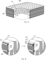
- FIG. 12 is a schematic view of a twelfth embodiment:
- FIG. 13 is a schematic view of a thirteenth embodiment:
- FIG. 14 is a schematic view of a sixteenth embodiment:
- FIG. 15 is a schematic view showing the process for manufacturing tensioning strips of the sixteenth embodiment:
- FIG. 16 is a schematic view showing the process for manufacturing tensioning strips of the sixteenth embodiment:
- FIG. 17 is an enlarged view of portion “B” of FIG. 16 ;
- FIG. 18 is a schematic view showing the process for manufacturing inflatable product of the sixteenth embodiment:
- FIG. 19 is an enlarged view of portion “C” of FIG. 18 showing the outer surface or inner surface of a top sheet and a bottom sheer of the sixteenth embodiment has a third auxiliary fusion piece thereon:
- FIG. 20 is an enlarged view of portion “C” of FIG. 18 showing the outer surface or inner surface of a top sheet and a bottom sheer of the sixteenth embodiment has a third auxiliary fusion piece and a first auxiliary reinforcement piece thereon:
- FIG. 21 is an enlarged view of portion “C” of FIG. 18 showing the outer surface or inner surface of a top sheet and a bottom sheer of the sixteenth embodiment has a fiber glue layer thereon:
- FIG. 22 is a schematic view of an eighteenth embodiment:
- FIG. 23 is a schematic view of a nineteenth embodiment:
- FIG. 24 is a schematic view of a twentieth embodiment:
- FIG. 25 is a schematic view of a portion of FIG. 24 ( FIG. 25 a is a schematic view of the portion, and FIG. 25 b depicts the fusion):
- FIG. 26 is a schematic view of a twenty-first embodiment:
- FIG. 27 is a schematic view of a twenty-second embodiment ( FIG. 27 a is a schematic view of a portion, and FIG. 27 b is a schematic view of back sealing by fusion):
- FIG. 28 is a schematic view of a twenty-third embodiment:
- FIG. 29 is a schematic view of a twenty-fourth embodiment:
- FIG. 30 is a schematic view of a twenty-fifth embodiment:
- FIG. 31 is a schematic view of a twenty-sixth embodiment
- FIG. 32 is a schematic view of a portion of FIG. 31 :
- FIG. 33 is a schematic view of a twenty-seventh embodiment:
- FIG. 34 is a schematic view of a twenty-eighth embodiment:
- FIG. 35 is a schematic view of a portion of FIG. 34 :
- FIG. 36 is a schematic view of a twenty-ninth embodiment:
- FIG. 37 is a schematic view of a thirtieth embodiment:
- FIG. 38 is a schematic view of the thirtieth embodiment:
- FIG. 39 is a schematic view of a portion of FIG. 38 ;
- FIG. 40 is a schematic view of a thirty-first embodiment:
- FIG. 41 is a schematic view of a thirty-second embodiment:
- FIG. 42 is a schematic view of a thirty-third embodiment ( FIG. 42 a shows the sewing and fusion at an early stage, and FIG. 42 b shows all the fusion at a late stage);
- FIG. 43 is a schematic view of a thirty-fourth embodiment ( FIG. 43 a shows the sewing and fusion at an early stage, and FIG. 43 b shows all the fusion at a late stage);
- FIG. 44 is a schematic view of a thirty-fifth embodiment
- FIG. 45 is a schematic view of a thirty-sixth embodiment:
- FIG. 46 is a schematic view of a thirty-seventh embodiment
- FIG. 47 is a schematic view of a thirty-eighth embodiment
- FIG. 48 is a schematic view of a thirty-ninth embodiment.
- a fusion structure of an inflatable product includes a fusion unit, and the fusion unit includes a target fusion layer 1 , a first fusion reinforcement layer 2 and a first auxiliary fusion layer 3 which are sequentially arranged.
- the target fusion layer 1 , the first fusion reinforcement layer 2 and the first auxiliary fusion layer 3 are connected together by a single fusion.
- the target fusion layer 1 is made of an airtight polymer material (e.g. plastic sheet) and can be used as surface material (e.g. top sheet, bottom sheet or periphery sheet) of the inflatable product.
- the first fusion reinforcement layer 2 is made of a flexible anti-stretch material (e.g.
- the first auxiliary fusion layer 3 is made of the same material as the target fusion layer 1 , and therefore the first auxiliary fusion layer 3 and the target fusion layer 1 can be fused together.
- the first auxiliary fusion layer 3 not only can be used as a surface material (e.g. top sheet, bottom sheet or periphery sheet) of the inflatable product, but also enables connection of the first fusion reinforcement layer 2 to the target fusion layer 1 during the fusion.
- a fusion structure of an inflatable product includes a fusion unit, and the fusion unit includes a target fusion layer 1 , a second auxiliary fusion layer 4 , a first fusion reinforcement layer 2 and a first auxiliary fusion layer 3 which are sequentially arranged.
- the target fusion layer 1 , the second auxiliary fusion layer 4 , the first fusion reinforcement layer 2 and the first auxiliary fusion layer 3 are connected together by a single fusion.
- the fusion structure of this form is formed by additionally providing the second auxiliary fusion layer 4 between the target fusion layer 1 and the first fusion reinforcement layer 2 of the fusion structure of the first embodiment. Because the second auxiliary fusion layer 4 is provided, the fusion structure of this form is several times higher than the fusion structure of the first embodiment in strength.
- the second auxiliary fusion layer 4 functions the same as the first auxiliary fusion layer 3 described in the first embodiment.
- a fusion structure of an inflatable product includes a fusion unit, and the fusion unit includes a target fusion layer 1 , a second auxiliary fusion layer 4 , a first fusion reinforcement layer 2 and a first auxiliary fusion layer 3 which are sequentially arranged.
- a periphery of the second auxiliary fusion layer 4 is connected to the target fusion layer 1 by a first fusion, and the first fusion reinforcement layer 2 and the first auxiliary fusion layer 3 are connected to the second auxiliary fusion layer 4 and the target fusion layer 1 by a second fusion, wherein the fusion portions formed by the first fusion and the second fusion are not overlapped.
- the fusion structure of this form is similar to the fusion structure described in the second embodiment, and the difference therebetween is that the fusion structure of this form is formed by twice fusion.
- the first fusion is done for connecting the periphery of the second auxiliary fusion layer 4 and the target fusion layer 1
- the second fusion is done for connecting the first fusion reinforcement layer 2 , the first auxiliary fusion layer 3 , the second auxiliary fusion layer 4 and the target fusion layer 1 .
- a fusion structure of an inflatable product includes a fusion unit, and the fusion unit includes a target fusion layer 1 , a second auxiliary fusion layer 4 , a first fusion reinforcement layer 2 and a first auxiliary fusion layer 3 which are sequentially arranged.
- the second auxiliary fusion layer 4 is connected to the target fusion layer 1 by a first fusion
- the first fusion reinforcement layer 2 and the first auxiliary fusion layer 3 are connected to the second auxiliary fusion layer 4 and the target fusion layer 1 by a second fusion, wherein a fusion portion formed by the first fusion is greater than that of the second fusion in area, and the fusion portion formed by the second fusion does not extend beyond that formed by the first fusion.
- the fusion structure of this form is the same as the fusion structure described in the third embodiment in structure, times of fusion and sequence of fusion, and the difference therebetween is that in the fusion structure of the third embodiment, the fusion portions formed by the first fusion and the second fusion are not overlapped while in the fusion structure of this form, the fusion portion formed by the first fusion is greater than that formed by the second fusion in area, and the fusion portion formed by the second fusion does not extend beyond that formed by the first fusion.
- a fusion structure of an inflatable product includes a fusion unit, and the fusion unit includes a target fusion layer 1 , a second fusion reinforcement layer 5 , a second auxiliary fusion layer 4 , a first fusion reinforcement layer 2 and a first auxiliary fusion layer 3 which are sequentially arranged.
- the second fusion reinforcement layer 5 and the second auxiliary fusion layer 4 are connected to the target fusion layer 1 by a first fusion
- the first fusion reinforcement layer 2 and the first auxiliary fusion layer 3 are connected to the second fusion reinforcement layer 5 , the second auxiliary fusion layer 4 and the target fusion layer 1 by a second fusion
- a fusion portion formed by the first fusion is greater than that formed by the second fusion in area
- the fusion portion formed by the second fusion does not extend beyond that formed by the first fusion.
- the fusion structure of this form is formed by additionally providing the second fusion reinforcement layer 5 between the target fusion layer 1 and the second auxiliary fusion layer 4 of the fusion structure of the fourth embodiment. Because the second fusion reinforcement layer 5 is provided, the fusion structure of this form is at least five times higher than the fusion structure of the fourth embodiment in strength.
- the second fusion reinforcement layer 5 functions the same as the first fusion reinforcement layer 2 described in the first embodiment.
- a fusion structure of an inflatable product includes a fusion unit, and the fusion unit includes a third auxiliary fusion layer 6 , a third fusion reinforcement layer 7 , a target fusion layer 1 , a second auxiliary fusion layer 4 , a first fusion reinforcement layer 2 and a first auxiliary fusion layer 3 which are sequentially arranged.
- the third auxiliary fusion layer 6 , the third fusion reinforcement layer 7 and the second auxiliary fusion layer 4 are connected to the target fusion layer 1 by a first fusion
- the first fusion reinforcement layer 2 and the first auxiliary fusion layer 3 are connected to the third auxiliary fusion layer 6 , the third fusion reinforcement layer 7 , the second auxiliary fusion layer 4 and the target fusion layer 1 by a second fusion, wherein a fusion portion formed by the first fusion is greater than that formed by the second fusion in area, and the fusion portion formed by the second fusion does not extend beyond that formed by the first fusion.
- the third auxiliary fusion layer 6 functions the same as the first auxiliary fusion layer 3 described in the first embodiment
- the third fusion reinforcement layer 7 functions the same as the first fusion reinforcement layer 2 described in the first embodiment.
- a fusion structure of an inflatable product includes a first fusion unit and a second fusion unit.
- the first fusion unit includes a target fusion layer 1 , a first fusion reinforcement layer 2 and a first auxiliary fusion layer 3 which are sequentially arranged.
- the target fusion layer 1 , the first fusion reinforcement layer 2 and the first auxiliary fusion layer 3 are connected by a first fusion.
- the second fusion unit is same as the first fusion unit in structure, and the first fusion unit and the second fusion unit are connected by a second fusion.
- the first auxiliary fusion layer 3 of the first fusion unit is attached to the first auxiliary fusion layer 3 of the second fusion unit.
- a fusion portion formed by the first fusion is greater than that formed by the second fusion in area, and the fusion portion formed by the second fusion does not extend beyond that formed by the first fusion.
- the fusion structure of this form is formed by fusing two fusion structures described in the first embodiment. The fusion structure of this form has the greatest strength among the above-described fusion structures.
- An inflatable product includes a top sheet 8 and a bottom sheet 9 , and peripheries of the top sheet 8 and the bottom sheet 9 are fused by any of the fusion structures described in the first, second, third, fourth, fifth and sixth embodiments, respectively shown in FIGS. 8 A, 8 B, 8 C, 8 D, 8 E and 8 F .
- An air chamber is formed between the top sheet 8 and the bottom sheet 9 .
- the top sheet 8 can be regarded as the target fusion layer 1 of the fusion structure
- the bottom sheet 9 can be regarded as the first auxiliary fusion layer 3 of the fusion structure.
- an inflatable product includes a top sheet 8 and a bottom sheet 9 , and peripheries of the top sheet 8 and the bottom sheet 9 are fused by the fusion structure described in the seventh embodiment.
- An air chamber is formed between the top sheet 8 and the bottom sheet 9 .
- the top sheet 8 can be regarded as the target fusion layer 1 of the first fusion unit
- the bottom sheet 9 can be regarded as the target fusion layer 1 of the second fusion unit.
- an inflatable product includes a top sheet 8 and a bottom sheet 9 , and peripheries of the top sheet 8 and the bottom sheet 9 are directly fused to form a plurality of linear fusion sites where the fusion structures described in the first, second, third, fourth, fifth and sixth embodiments are formed.
- the fusion sites are arranged to form a plurality of spaces between the top sheet 8 and the bottom sheet 9 into air chambers with a predetermined shape.
- the top sheet 8 can be regarded as the target fusion layer 1 of the fusion structure
- the bottom sheet 9 can be regarded as the first auxiliary fusion layer 3 of the fusion structure.
- an inflatable product includes a top sheet 8 and a bottom sheet 9 , and peripheries of the top sheet 8 and the bottom sheet 9 are directly fused to form a plurality of linear fusion sites where the fusion structure described in the seventh embodiment are formed.
- the fusion sites are arranged so that a plurality of spaces formed between the top sheet 8 and the bottom sheet 9 are air chambers with a predetermined shape.
- the top sheet 8 can be regarded as the target fusion layer 1 of the first fusion unit
- the bottom sheet 9 can be regarded as the first auxiliary fusion layer 3 of the second fusion unit.
- an inflatable product includes a top sheet 8 , a plurality of tensioning strips 11 and a bottom sheet 9 . Peripheries of the top sheet 8 and the bottom sheet 9 are directly fused, and the tensioning strips 11 are connected to inner surfaces of the top sheet 8 and the bottom sheet 9 by any of the fusion structures described in the first, second, third, fourth, fifth and sixth embodiments.
- the top sheet 8 and the bottom sheet 9 can be regarded as the target fusion layer 1 of the fusion structure, and the tensioning strips 11 can be regarded as the first fusion reinforcement layer 2 of the fusion structure.
- an inflatable product includes a top sheet 8 , a periphery sheet 10 , a plurality of tensioning strips 11 and a bottom sheet 9 .
- Two sides of the periphery sheet 10 are directly welded to peripheries of the top sheet 8 and the bottom sheet 9 for forming an air chamber, and the tensioning strips 11 are welded to inner surfaces of the top sheet 8 and the bottom sheet 9 by any of the fusion structures described in the first, second, third, fourth, fifth and sixth embodiments.
- the top sheet 8 and the bottom sheet 9 can be regarded as the target fusion layer 1 of the fusion structure, and the tensioning strips 11 can be regarded as the first fusion reinforcement layer 2 of the fusion structure.
- An inflatable product includes a top sheet 8 , a periphery sheet 10 , a plurality of tensioning strips 11 and a bottom sheet 9 .
- Two sides of the periphery sheet 10 are connected to peripheries of the top sheet 8 and the bottom sheet 9 by any of the fusion structures described in the first, second, third, fourth, fifth and sixth embodiments for forming an air chamber.
- the top sheet 8 and the bottom sheet 9 can be regarded as the target fusion layer 1 of the fusion structure, and the periphery sheet 10 can be regarded as the first auxiliary fusion layer 3 of the fusion structure.
- the tensioning strips 11 are connected to inner surfaces of the top sheet 8 and the bottom sheet 9 by fusion.
- the tensioning strips 11 are connected to the inner surfaces of the top sheet 8 and the bottom sheet 9 by any of the fusion structures described in the first, second, third, fourth, fifth and sixth embodiments.
- the top sheet 8 and the bottom sheet 9 can be regarded as the target fusion layer 1 of the fusion structure, and the tensioning strips 11 can be regarded as the first fusion reinforcement layer 2 of the fusion structure.
- the fifteenth embodiment is similar to the fourteenth embodiment, and the difference therebetween is that two sides of the periphery sheet 10 is connected to peripheries of the top sheet 8 and the bottom sheet 9 by the fusion structure described in the seventh embodiment for forming an air chamber.
- the top sheet 8 and the bottom sheet 9 can be regarded as the target fusion layer 1 of the first fusion unit of the fusion structure, and the periphery sheet 10 can be regarded as the target fusion layer 1 of the second fusion unit of the fusion structure.
- the tensioning strips 11 are connected to inner surfaces of the top sheet 8 and the bottom sheet 9 by fusion.
- an inflatable product includes a top sheet 8 , a periphery sheet 10 , a plurality of tensioning strips 11 and a bottom sheet 9 .
- Two sides of the periphery sheet 10 are connected to peripheries of the top sheet 8 and the bottom sheet 9 by any of the fusion structures described in the first, second, third, fourth, fifth and sixth embodiments for forming an air chamber.
- the top sheet 8 and the bottom sheet 9 can be regarded as the target fusion layer 1 of the fusion structure, and the periphery sheet 10 can be regarded as the first auxiliary fusion layer 3 of the fusion structure.
- the tensioning strips 11 are connected to inner surfaces of the top sheet 8 and the bottom sheet 9 by fusion.
- Each of the tensioning strips 11 includes a strip body 111 , a first auxiliary fusion piece 12 and a second auxiliary fusion piece 13 .
- the strip body 111 is connected to the inner surfaces of the top sheet 8 and the bottom sheet 9 by fusion where the first auxiliary fusion piece 12 and the second auxiliary fusion piece 13 are provided to hold and fuse with the strip body 111 .
- the first auxiliary fusion piece 12 or the second auxiliary fusion piece 13 is fixed to a side of the strip body 111 .
- the strip body 111 is made of a flexible anti-stretch material (e.g. mesh fabric) having a plurality of through holes and is configured to restrict or resist the pulling force produced by expansion of the inflatable product.
- the first auxiliary fusion piece 12 and the second auxiliary fusion piece 13 are made of the same material (that is, airtight polymer material) (e.g. plastic sheet) as the top sheet 8 and the bottom sheet 9 and enable connection of the strip body 111 to the inner surfaces of the top sheet 8 and the bottom sheet 9 during the fusion.
- airtight polymer material e.g. plastic sheet
- the inner surfaces of the top sheet 8 and the bottom sheet 9 can be directly connected to the tensioning strips 11 by fusion.
- auxiliary structures can be provided at the locations where the inner surfaces of the top sheet 8 and the bottom sheet 9 are connected to the tensioning strips 11 .
- the auxiliary structure can be a third auxiliary fusion piece 14 which is provided at the location where at least one of the inner surfaces of the top sheet 8 and the bottom sheet 9 fuses with the tensioning strips 11 .
- the auxiliary structure can also be a first auxiliary reinforcement piece 15 and a third auxiliary fusion piece 14 which are provided at the location where at least one of the outer surfaces and inner surfaces of the top sheet 8 and the bottom sheet 9 fuses with the tensioning strips 11 .
- the first auxiliary reinforcement piece 15 is attached to at least one of the outer surfaces and the inner surfaces of the top sheet 8 and the bottom sheet 9 , and the third auxiliary fusion piece 14 is placed over the first auxiliary reinforcement piece 15 .
- the auxiliary structure can directly fuse with at least one of the outer surfaces and the inner surfaces of the top sheet 8 and the bottom sheet 9 , and then the tensioning strips 11 are connected thereto by fusion.
- the auxiliary structure is kept in position and then the tensioning strips 11 are fused with the auxiliary structure and at least one of the outer surfaces and the inner surfaces of the top sheet 8 and the bottom sheet 9 .
- the auxiliary structure can be a fiber glue layer 16 which has a plurality of through holes and is applied to the location where at least one of outer surfaces and the inner surfaces of the top sheet 8 and the bottom sheet 9 fuses with the tensioning strips 11 .
- the first auxiliary reinforcement piece 15 is made of a flexible anti-stretch material (e.g. mesh fabric) having a plurality of through holes and is configured to restrict or resist pulling force produced by expansion of the inflatable product during inflation.
- the fiber glue layer 16 is formed by applying fiber glue (glue with fiber added therein) to the location where at least one of the outer surfaces and the inner surfaces of the top sheet 8 and the bottom sheet 9 fuses with the tensioning strips 11 , for restricting or resisting the pulling force produced by expansion of the inflatable product during inflation.
- the third auxiliary fusion piece 14 is made of the same material as the top sheet 8 and the bottom sheet 9 that facilitates connection of the first auxiliary reinforcement piece 15 to at least one of the outer surfaces and the inner surfaces of the top sheet 8 and the bottom sheet 9 by fusion
- a method for manufacturing the tensioning strips 11 includes following steps:
- step S 1 a roll of mesh fabric is loaded and unrolled.
- step S 2 a roll of the first auxiliary fusion piece 12 and a roll of the second auxiliary fusion piece 13 are cut into strips and the strips are placed at predetermined locations on an upper side and a lower side of the mesh fabric.
- a roll of the first auxiliary fusion piece 12 or a roll of the second auxiliary fusion piece 13 is cut into strips and the strips are placed on a side of the mesh fabric.
- step S 3 the strips cut from the first auxiliary fusion piece 12 and the second auxiliary fusion piece 13 are placed to hold the mesh fabric and fuse with the mesh fabric.
- the strips cut from the first auxiliary fusion piece 12 or the second auxiliary fusion piece 13 are fixed to a side of the mesh fabric.
- step S 4 the mesh fabric which fuses with the strips cut from the first auxiliary fusion piece 12 and the second auxiliary fusion piece 13 is cut into strips for obtaining tensioning strips 11 .
- the mesh fabric a side of which has the strips cut from the first auxiliary fusion piece 12 or the second auxiliary fusion piece 13 attached thereto, is cut into strips for obtaining the tensioning strips 11 .
- an alternative method for manufacturing the tensioning strips 11 includes the following steps:
- step S 1 ′ a roll of mesh fabric is loaded and unrolled.
- step S 2 ′ the mesh fabric is cut into strips for obtaining the strip body 111 .
- step S 3 ′ the first auxiliary fusion piece 12 and the second auxiliary fusion piece 13 are respectively placed and positioned at predetermined locations on an upper side and a lower side of the strip body 111 .
- the first auxiliary fusion piece 12 or the second auxiliary fusion piece 13 is placed and positioned at predetermined location on a side of the strip body 111 .
- step S 4 ′ the first auxiliary fusion piece 12 and the second auxiliary fusion piece 13 are placed to hold the strip body 111 and fuse with the strip body 111 for obtaining the tensioning strips 11 .
- the first auxiliary fusion piece 12 or the second auxiliary fusion piece 13 is fixed to a side of the strip body 111 for obtaining the tensioning strips 11 .
- a method for manufacturing the inflatable product includes the following steps:
- step S 5 rolls of the top sheet 8 and the bottom sheet 9 are loaded, unrolled and kept in position.
- step S 6 the tensioning strips 11 , which are manufactured by the above-described method, are placed at predetermined locations between the top sheet 8 and the bottom sheet 9 , and the parts of the tensioning strips 11 which have the first auxiliary fusion pieces 12 and the second auxiliary fusion pieces 13 thereon are fused with the inner surfaces of the top sheet 8 and the bottom sheet 9 .
- the parts of the tensioning strips 11 a side of which has the first auxiliary fusion pieces 12 or the second auxiliary fusion pieces 13 fixed thereto, are fused with the inner surfaces of the top sheet 8 and the bottom sheet 9 .
- step S 7 the sides of the periphery sheet 10 are connected to the peripheries of the top sheet 8 and the bottom sheet 9 by any of the fusion structures described in the first, second, third, fourth, fifth and sixth embodiments for forming the air chamber and obtaining the inflatable product.
- an alternative method for manufacturing the inflatable product includes the following steps:
- step S 5 rolls of the top sheet 8 and the bottom sheet 9 are loaded and unrolled and kept in position, and the third auxiliary fusion pieces 14 are fused with the outer surfaces or the inner surfaces of the top sheet 8 and the bottom sheet 9 at predetermined locations where the tensioning strips 11 are going to fuse with the top sheet 8 and the bottom sheet 9 .
- step S 6 the tensioning strips 11 which are manufactured by the above-described method are sent and kept at the predetermined locations between the top sheet 8 and the bottom sheet 9 , and the parts of the tensioning strips 11 having the first auxiliary fusion pieces 12 and the second auxiliary fusion pieces 13 thereon are fused with the parts of the inner surfaces of the top sheet 8 and the bottom sheet 9 having the third auxiliary fusion pieces 14 thereon.
- the parts of the tensioning strips 11 each of which has the first auxiliary fusion piece 12 or the second auxiliary fusion piece 13 fixed to a side thereof, are fused with the parts of the inner surfaces of the top sheet 8 and the bottom sheet 9 which have the third auxiliary fusion pieces 14 fixed thereto.
- step S 7 the sides of the periphery sheet 10 are connected to the peripheries of the top sheet 8 and the bottom sheet 9 by any of the fusion structures described in the first, second, third, fourth, fifth and sixth embodiments for forming the air chamber and obtaining the inflatable product.
- an alternative method for manufacturing the inflatable product includes the following steps:
- step S 5 rolls of the top sheet 8 and the bottom sheet 9 are loaded, unrolled and kept in position, and the first auxiliary reinforcement pieces 15 and the third auxiliary fusion pieces 14 are placed on the outer surfaces or the inner surfaces of the top sheet 8 and the bottom sheet 9 at predetermined locations where the top sheet 8 and the bottom sheet 9 are going to fuse with the tensioning strips 11 , wherein the first auxiliary reinforcement pieces 15 and the third auxiliary fusion pieces 14 are only kept in position without fusing with other elements.
- step S 6 the tensioning strips 11 which are manufactured by the above-described method are sent and positioned at predetermined locations between the top sheet 8 and the bottom sheet 9 , and the parts of the tensioning strips 11 which have the first auxiliary fusion pieces 12 and the second auxiliary fusion pieces 13 thereon are fused with the parts of the inner surfaces of the top sheet 8 and the bottom sheet 9 which have the first auxiliary reinforcement pieces 15 and the third auxiliary fusion pieces 14 thereon.
- the parts of the tensioning strips 11 each of which has the first auxiliary fusion piece 12 or the second auxiliary fusion piece 13 fixed to a side thereof, are fused with the parts of the inner surfaces of the top sheet 8 and the bottom sheet 9 which have the third auxiliary fusion pieces 14 fixed thereto.
- step S 7 the sides of the periphery sheet 10 are connected to the peripheries of the top sheet 8 and the bottom sheet 9 by any of the fusion structures described in the first, second, third, fourth, fifth and sixth embodiments for forming the air chamber and obtaining the inflatable product.
- a further alternative method for manufacturing the inflatable product includes the following steps:
- step S 5 rolls of the top sheet 8 and the bottom sheet 9 are loaded, unrolled and kept in position, the first auxiliary reinforcement pieces 15 and the third auxiliary fusion pieces 14 are placed on the outer surfaces or the inner surfaces of the top sheet 8 and the bottom sheet 9 at predetermined locations where the top sheet 8 and the bottom sheet 9 are going to fuse with the tensioning strips 11 , and the first auxiliary reinforcement pieces 15 and the third auxiliary fusion pieces 14 are fused with the inner surfaces of the top sheet 8 and the bottom sheet 9 .
- step S 6 the tensioning strips 11 which are manufactured by the above-described method are placed at predetermined locations between the top sheet 8 and the bottom sheet 9 , and the parts of the tensioning strips 11 which have the first auxiliary fusion pieces 12 and the second auxiliary fusion pieces 13 thereon are fused with the parts of the inner surfaces of the top sheet 8 and the bottom sheet 9 which have the first auxiliary reinforcement pieces 15 and the third auxiliary fusion pieces 14 thereon.
- the parts of the tensioning strips 11 each of which has the first auxiliary fusion piece 12 or the second auxiliary fusion piece 13 fixed to a side thereof, are fused with the parts of the inner surfaces of the top sheet 8 and the bottom sheet 9 which have the first auxiliary reinforcement pieces 15 and the third auxiliary fusion pieces 14 thereon.
- step S 7 the sides of the periphery sheet 10 are connected to the peripheries of the top sheet 8 and the bottom sheet 9 by any of the fusion structures described in the first, second, third, fourth, fifth and sixth embodiments for forming the air chamber and obtaining the inflatable product.
- a yet further alternative method for manufacturing the inflatable product includes the following steps:
- step S 5 rolls of the top sheet 8 and the bottom sheet 9 are loaded, unrolled and kept in position, and a fiber glue layer 16 which has a plurality of through holes is formed on the outer surfaces or the inner surfaces of the top sheet 8 and the bottom sheet 9 at predetermined locations where the top sheet 8 and the bottom sheet 9 are going to fuse with the tensioning strips 11 .
- step S 6 the tensioning strips 11 which are manufactured by the above-described method are sent and positioned at predetermined locations between the top sheet 8 and the bottom sheet 9 , and the parts of the tensioning strips 11 which have the first auxiliary fusion pieces 12 and the second auxiliary fusion pieces 13 thereon are fused with the parts of the inner surfaces of the top sheet 8 and the bottom sheet 9 which have the fiber glue layer 16 formed thereon, wherein the fiber glue layer 16 has through holes.
- the parts of the tensioning strips 11 are fused with the parts of the inner surfaces of the top sheet 8 and the bottom sheet 9 which have the fiber glue layer 16 formed thereon, wherein the fiber glue layer 16 has through holes.
- step S 7 the sides of the periphery sheet 10 are connected to the peripheries of the top sheet 8 and the bottom sheet 9 by any of the fusion structures described in the first, second, third, fourth, fifth and sixth embodiments for forming the air chamber and obtaining the inflatable product.
- the seventeenth embodiment is similar to the sixteenth embodiment, and the difference therebetween is that two sides of the periphery sheet 10 are connected to peripheries of the top sheet 8 and the bottom sheet 9 by the fusion structure described in the seventh embodiment for forming an air chamber.
- the top sheet 8 and the bottom sheet 9 can be regarded as the target fusion layer 1 of the first fusion unit of the fusion structure, and the periphery sheet 10 can be regarded as the target fusion layer 1 of the second fusion unit of the fusion structure.
- the tensioning strips 11 are connected to inner surfaces of the top sheet 8 and the bottom sheet 9 by fusion.
- an inflatable product includes an inflatable body 100 .
- the inflatable body 100 includes two target fusion layers 110 which are connected by fusion, thereby forming a fusion portion.
- the fusion portion includes a first fusion portion 121 and a second fusion portion 122 .
- An anti-stretch sheet 200 is disposed outside the inflatable body 100 for covering the inflatable body 100 .
- the anti-stretch sheet 200 includes two fusion reinforcement layers 210 , a fusion portion is formed thereon, and the fusion portion includes a first fusion portion 221 and a second fusion portion 222 .
- the first fusion portion 121 and the second fusion portion 122 of the target fusion layers 110 are placed in contact with each other.
- the first fusion portion 221 and the second fusion portion 222 of the fusion reinforcement layers 210 are respectively placed in contact with the first fusion portion 121 and the second fusion portion 122 of the target fusion layers 110 .
- the auxiliary fusion layers 410 , 420 are placed in contact with the first fusion portion 221 and the second fusion portion 222 of the fusion reinforcement layers 210 .
- the inflatable product provided with an air chamber is formed by fusion and has an angle at the fusion location after inflation of the inflatable body.
- the nineteenth embodiment is similar to the eighteenth embodiment, and the difference therebetween is that an anti-stretch sheet 300 is provided within the inflatable body 100 for being covered by the inflatable body 100 .
- the anti-stretch sheet 300 includes two fusion reinforcement layers 310 , a fusion portion is formed thereon, and the fusion portion includes a first fusion portion 321 and a second fusion portion 322 .
- An auxiliary fusion layer 450 is provided between the first fusion portion 321 and the second fusion portion 322 .
- the inflatable product having an air chamber is formed by fusion and has an angle at the fusion location.
- an inflatable tent includes an inflatable tube 20 and a tent cloth 30 .
- the inflatable tube 20 includes a tube body 22 and a tube end (not shown) disposed on an end portion of the tube body, and the tube body 22 and the tube end are connected by fusion to form an air chamber.
- the tube body 22 includes an inflatable body.
- the inflatable body is formed by two target fusion layers 110 which are arranged symmetrically and connected by fusion to form a fusion portion thereon.
- the fusion portion includes a first fusion portion 121 and a second fusion portion 122 ( FIG. 25 a only shows a side of fusion structure, while the other side of fusion structure is omitted).
- An anti-stretch sheet is disposed outside the inflatable body for covering the inflatable body.
- the anti-stretch sheet includes two fusion reinforcement layers 210 , a fusion portion is formed thereon, and the fusion portion includes a first fusion portion 221 and a second fusion portion 222 .
- the inflatable tube 20 further includes a plurality of airtight auxiliary fusion layers which are fused with the fusion portion of the inflatable body and the fusion portion of the anti-stretch sheet.
- the airtight auxiliary fusion layers include auxiliary fusion layers 410 , 420 .
- the target fusion layers 110 and the auxiliary fusion layers 410 , 420 are made of polyvinyl chloride (PVC), and the fusion reinforcement layers 210 are mesh fabric.
- the first fusion portion 121 and the second fusion portion 122 of the target fusion layers 110 are placed in contact with each other.
- the first fusion portion 221 and the second fusion portion 222 of the fusion reinforcement layers 210 are respectively placed in contact with the first fusion portion 121 and the second fusion portion 122 of the target fusion layers 110 .
- the auxiliary fusion layers 410 , 420 are placed in contact with the first fusion portion 221 and the second fusion portion 222 of the fusion reinforcement layers 210 .
- the tube body 22 having the air chamber is formed by fusion and has an angle at the fusion location after inflation of the inflatable body.
- the first fusion portion 121 of the target fusion layers 110 , the first fusion portion 221 of the fusion reinforcement layers 210 and the auxiliary fusion layer 410 are fused, the second fusion portion 122 of the target fusion layers 110 , the second fusion portion 222 of the fusion reinforcement layers 210 and the auxiliary fusion layer 420 are fused, and then the two fusion units are fused.
- the twenty-first embodiment is similar to the twentieth embodiment, and the difference therebetween is that an auxiliary fusion layer 430 is additionally provided between the first fusion portion 121 of the target fusion layers 110 and the first fusion portion 221 of the fusion reinforcement layers 210 , and an auxiliary fusion layer 440 is additionally provided between the second fusion portion 122 of the target fusion layers 110 and the second fusion portion 222 of the fusion reinforcement layers 210 .
- the tube body 22 having the air chamber is formed by fusion and has an angle at the fusion location after inflation of the inflatable body.
- the first fusion portion 121 of the target fusion layers 110 , the auxiliary fusion layer 430 , the first fusion portion 221 of the fusion reinforcement layers 210 and the auxiliary fusion layer 410 are fused, the second fusion portion 122 of the target fusion layers 110 , the auxiliary fusion layer 440 , the second fusion portion 222 of the fusion reinforcement layers 210 and the auxiliary fusion layer 420 are fused, and then the two fusion units are fused.
- the twenty-second embodiment is similar to the twentieth embodiment, and the difference therebetween is that the first fusion portion 121 of the target fusion layer 110 is placed in contact with the first fusion portion 221 of the fusion reinforcement layer 210 , the second fusion portion 122 of the target fusion layer 110 is placed in contact with the first fusion portion 221 of the fusion reinforcement layer 210 , the second fusion portion 222 of the fusion reinforcement layer 210 is placed in contact with the second fusion portion 122 of the target fusion layer 110 , and the auxiliary fusion layer 420 is placed in contact with the second fusion portion 222 of the fusion reinforcement layer 210 .
- FIG. 1 the first fusion portion 121 of the target fusion layer 110 is placed in contact with the first fusion portion 221 of the fusion reinforcement layer 210
- the second fusion portion 222 of the fusion reinforcement layer 210 is placed in contact with the second fusion portion 122 of the target fusion layer 110
- the auxiliary fusion layer 420 is placed in contact with the second fusion portion
- the target fusion layer 110 is back sealed by fusion to form the tube body 22 having the air chamber.
- the first fusion portion 121 of the target fusion layer 110 , the first fusion portion 221 of the fusion reinforcement layer 210 , and the second fusion portion 122 of the target fusion layer 110 are simultaneously fused, and then are fused with the second fusion portion 222 of the fusion reinforcement layer 210 and the auxiliary fusion layer 420 .
- the twenty-third embodiment is similar to the twenty-second embodiment, and the difference therebetween is that the first fusion portion 121 of the target fusion layer 110 is placed in contact with the second fusion portion 122 of the target fusion layer 110 , the second fusion portion 122 of the target fusion layer 110 is placed in contact with the second fusion portion 222 of the fusion reinforcement layer 210 , the auxiliary fusion layer 420 is placed in contact with the second fusion portion 222 of the fusion reinforcement layer 210 , the first fusion portion 221 of the fusion reinforcement layer 210 is placed in contact with the auxiliary fusion layer 420 , and the auxiliary fusion layer 410 is placed in contact with the first fusion portion 221 of the fusion reinforcement layer 210 .
- the tube body 22 having the air chamber is formed by fusion and has a curved shape at the fusion location.
- the auxiliary fusion layer 420 , the second fusion portion 222 of the fusion reinforcement layer 210 and the second fusion portion 122 of the target fusion layer 110 are simultaneously fused, and then are fused with the first fusion portion 121 of the target fusion layer 110 , the first fusion portion 221 of the fusion reinforcement layer 210 and the auxiliary fusion layer 410 .
- the twenty-fourth embodiment is similar to the twenty-second embodiment, and the difference therebetween is that the first fusion portion 121 of the target fusion layer 110 , the first fusion portion 221 of the fusion reinforcement layer 210 , the second fusion portion 122 of the target fusion layer 110 , the second fusion portion 222 of the fusion reinforcement layer 210 and the auxiliary fusion layer 420 are simultaneously fused.
- the twenty-fifth embodiment is similar to the twenty-third embodiment, and the difference therebetween is that the auxiliary fusion layer 410 , the first fusion portion 221 of the fusion reinforcement layer 210 and the auxiliary fusion layer 420 are simultaneously welded, and then are fused with the second fusion portion 222 of the fusion reinforcement layer 210 and the second fusion portion 122 and the first fusion portion 121 of the target fusion layer 110 .
- an inflatable bed includes a top sheet 114 , a periphery sheet 112 and a bottom sheet, and peripheries of the three sheets are fused to form an inflatable body 100 .
- Fusion units are formed between the top sheet 114 and the periphery sheet 112 as well as between the periphery sheet 112 and the bottom sheet.
- the fusion units includes a first fusion portion 121 formed on the periphery of the periphery sheet, a second fusion portion 122 formed on the periphery of the top sheet, and a second fusion portion (not shown) formed on the periphery of the bottom sheet.
- the periphery sheet 112 is covered by an anti-stretch sheet, and the anti-stretch sheet includes a fusion reinforcement layer 220 with a first fusion portion 221 formed on the periphery thereof.
- the inflatable bed further includes a plurality of airtight auxiliary fusion layers, and the airtight auxiliary fusion layers include an auxiliary fusion layer 410 .
- the top sheet 114 , the periphery sheet 112 , the bottom sheet and the auxiliary fusion layer 410 are made of polyvinyl chloride (PVC), and the fusion reinforcement layer 220 is mesh fabric.
- the first fusion portion 121 of the periphery sheet 112 is placed in contact with the first fusion portion 221 of the fusion reinforcement layer 220 , the auxiliary fusion layer 410 is placed in contact with the first fusion portion 221 of the fusion reinforcement layer 220 , and the first fusion portion 121 of the periphery sheet 112 is placed in contact with the second fusion portion 122 of the top sheet 114 , so that they can be are firmly connected by fusion to form an angle at the fusion location.
- the first fusion portion 121 of the periphery sheet 112 , the first fusion portion 221 of the fusion reinforcement layer 220 and the auxiliary fusion layer 410 are simultaneously fused and then are fused with the second fusion portion 122 of the top sheet 114 .
- the way that the first fusion portion of the periphery sheet 112 is fused with the second fusion portion of the bottom sheet and the first fusion portion of the fusion reinforcement layer 220 is similar to the above-mentioned way, and therefore the descriptions thereof are omitted.
- middle of the fusion reinforcement layer 220 is provided with a plurality of auxiliary fusion layers 460 which are spaced and are firmly connected to the fusion reinforcement layer 220 and the periphery sheet 112 by fusion for improving the pressure bearing ability.
- the twenty-seventh embodiment is similar to the twenty-sixth embodiment, and the difference therebetween is that an auxiliary fusion layer 430 is additionally provided between the first fusion portion 121 of the periphery sheet and the first fusion portion 221 of the fusion reinforcement layer.
- an auxiliary fusion layer 430 is additionally provided between the first fusion portion 121 of the periphery sheet and the first fusion portion 221 of the fusion reinforcement layer.
- an inflatable bed includes a top sheet 114 , a periphery sheet 112 and a bottom sheet 113 , and peripheries of the three sheets are fused to form an inflatable body 100 .
- Fusion portions are formed between the top sheet 114 and the periphery sheet 112 as well as between the periphery sheet 112 and the bottom sheet 113 .
- the fusion portions includes a first fusion portion 121 formed on the periphery of the periphery sheet 112 , a second fusion portion 122 formed on the periphery of the top sheet 114 and a second fusion portion (not shown) formed on the periphery of the bottom sheet 113 .
- the inflatable bed further includes an anti-stretch sheet 200
- the anti-stretch sheet 200 includes a fusion reinforcement layer 220 covering the periphery sheet 112 , a fusion reinforcement layer 210 covering the top sheet 114 and a fusion reinforcement layer 230 covering the bottom sheet 113 .
- a second fusion portion 222 is formed on periphery of the fusion reinforcement layer 210
- a first fusion portion 221 is formed on periphery of the fusion reinforcement layer 220
- a second fusion portion is formed on periphery of the fusion reinforcement layer 230 .
- the inflatable bed further includes a plurality of airtight auxiliary fusion layers, and the airtight auxiliary fusion layers include an auxiliary fusion layer 410 and an auxiliary fusion layer 420 .
- the top sheet 114 , the periphery sheet 112 , the bottom sheet 113 and the auxiliary fusion layers 410 , 420 are made of polyvinyl chloride (PVC), and the fusion reinforcement layers 210 , 220 , 230 are mesh fabric.
- PVC polyvinyl chloride
- the first fusion portion 121 of the periphery sheet 112 is placed in contact with the first fusion portion 221 of the fusion reinforcement layer 220
- the auxiliary fusion layer 410 is placed in contact with the first fusion portion 221 of the fusion reinforcement layer 220 , so as to be connected by a first fusion.
- the second fusion portion 122 of the top sheet 114 is placed in contact with the second fusion portion 222 of the fusion reinforcement layer 210
- the auxiliary fusion layer 420 is placed in contact with the second fusion portion 222 of the fusion reinforcement layer 210 , so as to be connected by a second fusion.
- the first fusion portion 121 of the periphery sheet 112 is placed in contact with the second fusion portion 122 of the top sheet 114 . Then, the first fusion portion 121 and the second fusion portion 122 are firmly connected by the second fusion and have an angle at the fusion location after inflation of the inflatable body.
- the way to fuse the first fusion portion of the periphery sheet 112 , the second fusion portion of the bottom sheet 113 , the first fusion portion 221 of the fusion reinforcement layer 220 and the second fusion portion of the fusion reinforcement layer 230 is similar to the above-mentioned way, and therefore the descriptions thereof are omitted.
- middle of the fusion reinforcement layer 220 is provided with a plurality of auxiliary fusion layers 460 which are spaced and are firmly connected to the fusion reinforcement layer 220 and the periphery sheet 112 by fusion for improving the pressure bearing ability.
- the twenty-ninth embodiment is similar to the twenty-eighth embodiment, and the difference therebetween is that an auxiliary fusion layer 430 is additionally provided between the first fusion portion 121 of the periphery sheet and the first fusion portion 221 of the fusion reinforcement layer, an auxiliary fusion layer 440 is additionally provided between the second fusion portion 122 of the top sheet and the second fusion portion 222 of the fusion reinforcement layer, and an auxiliary fusion layer (not shown) is additionally provided between the second fusion portion of the bottom sheet and the second fusion portion of the fusion reinforcement layer.
- an inflatable pool includes an inflatable body 100 .
- the inflatable body 100 is formed by fusing a plurality of target fusion layers 110 , and a fusion portion is formed thereon.
- the fusion portion includes a first fusion portion 121 and a second fusion portion 122 .
- An anti-stretch sheet 200 is disposed outside the inflatable body 100 for covering the inflatable body 100 .
- the anti-stretch sheet 200 includes a plurality of fusion reinforcement layers 210 , and a fusion portion is formed thereon.
- the fusion portion includes a first fusion portion 221 and a second fusion portion 222 .
- the inflatable pool further includes a plurality of airtight auxiliary fusion layers which are firmly connected to the fusion portion of the inflatable body and the fusion portion of the anti-stretch sheet by fusion.
- the airtight auxiliary fusion layers include auxiliary fusion layers 410 , 420 .
- the target fusion layers 110 and the auxiliary fusion layers 410 , 420 are made of polyvinyl chloride (PVC), and the fusion reinforcement layers 210 are mesh fabric.
- the first fusion portion 121 and the second fusion portion 122 of the target fusion layers 110 are placed in contact with each other, the first fusion portion 221 and the second fusion portion 222 of the fusion reinforcement layers 210 are respectively placed in contact with the first fusion portion 121 and the second fusion portion 122 of the target fusion layers 110 , and the auxiliary fusion layers 410 , 420 are respectively placed in contact with the first fusion portion 221 and the second fusion portion 222 of the fusion reinforcement layers 210 , so that they can be firmly connected by fusion and have an angle at the fusion locations.
- the first fusion portion 121 of the target fusion layers 110 , the first fusion portion 221 of the fusion reinforcement layers 210 and the auxiliary fusion layer 410 are simultaneously fused
- the second fusion portion 122 of the target fusion layers 110 , the second fusion portion 222 of the fusion reinforcement layers 210 and the auxiliary fusion layer 420 are simultaneously fused, and then the above-mentioned structures which are individually fused have their fused portions firmly connected by further fusion.
- middle of the fusion reinforcement layer 210 is provided with a plurality of auxiliary fusion layers 460 which are spaced and are firmly connected to the fusion reinforcement layer 210 and the target fusion layer 110 by fusion for improving the pressure bearing ability.
- the thirty-first embodiment is similar to the thirtieth embodiment, and the difference therebetween is that an auxiliary fusion layer 430 is additionally provided between the first fusion portion 121 of the target fusion layer 110 and the first fusion portion 221 of the fusion reinforcement layer 210 , and an auxiliary fusion layer 440 is additionally provided between the second fusion portion 122 of the target fusion layer 110 and first fusion portion 222 of the fusion reinforcement layer 210 .
- the thirty-second embodiment is similar to the thirtieth embodiment, and the difference therebetween is that during the fusion, the first fusion portion 221 of the fusion reinforcement layer 210 and the auxiliary fusion layer 410 are fixed by sewing, the first fusion portion 222 of the fusion reinforcement layer 210 and the auxiliary fusion layer 420 are fixed by sewing, and the first fusion portion 121 and the second fusion portion 122 of the target fusion layer 110 are placed in contact with each other and then fused together to fix the whole fused portion.
- the thirty-third embodiment is similar to the thirty-first embodiment, and the difference therebetween is that during the fusion, the first fusion portion 221 of the fusion reinforcement layer 210 and the auxiliary fusion layer 410 are fixed by sewing, the auxiliary fusion layer 410 and the auxiliary fusion layer 430 are firmly connected by fusion and are then firmly connected to the first fusion portion 121 of the target fusion layer 110 by further fusion, the second fusion portion 222 of the fusion reinforcement layer 210 and the auxiliary fusion layer 420 are fixed by sewing, and the auxiliary fusion layer 420 and the auxiliary fusion layer 440 are firmly connected by fusion and are then firmly connected to the second fusion portion 122 of the target fusion layer 110 by further fusion.
- the first fusion portion 121 and the second fusion portion 122 of the target fusion layer 110 are placed in contact with each other, and then fused together to fix the whole fused portion.
- the thirty-fourth embodiment is similar to the thirty-third embodiment, and the difference therebetween is that during the fusion, the first fusion portion 221 of the fusion reinforcement layer and the auxiliary fusion layer 410 are fixed by sewing, the auxiliary fusion layer 410 and the auxiliary fusion layer 430 are firmly connected by fusion (fused at two different locations) and are then firmly connected to the first fusion portion 121 of the target fusion layer by further fusion, the second fusion portion 222 of the fusion reinforcement layer and the auxiliary fusion layer 420 are fixed by sewing, and the auxiliary fusion layer 420 and the auxiliary fusion layer 440 are firmly connected by fusion (fused at two different locations) and are then firmly connected to the second fusion portion 122 of the target fusion layer by further fusion.
- the first fusion portion 121 and the second fusion portion 122 of the target fusion layer are placed in contact with each other to fix the whole fused portion.
- fusion portions of an inflatable product are formed as a fusion structure, and the fusion structure includes a first fusion unit 910 and a second fusion unit ( FIG. 44 shows the first fusion unit 910 but does not show the second fusion unit) which are welded to each other.
- the way to produce the first fusion unit is that an auxiliary fusion layer 410 and an auxiliary fusion layer 430 are placed to firmly hold a fusion portion 221 of an anti-stretch sheet and are then firmly connected to a fusion portion 121 of an inflatable body by fusion.
- the anti-stretch sheet includes a target fusion layer 210
- the inflatable body includes a target fusion layer 110 .
- the way to produce the second fusion unit is same as that to produce the first fusion unit.
- fusion portions of an inflatable product are formed as a fusion structure, and the fusion structure includes a first fusion unit 910 and a second fusion unit ( FIG. 45 shows the first fusion unit 910 but does not show the second fusion unit) which are fused with each other.
- the way to produce the first fusion unit is that an auxiliary fusion layer 430 or a fusion reinforcement layer 500 is fixed to a fusion portion 221 of an anti-stretch sheet by sewing and is then firmly connected to a fusion portion 121 of an inflatable body by fusion.
- the fusion portion 121 of the inflatable body is placed in contact with the auxiliary fusion layer 430 or the fusion reinforcement layer 500 .
- the anti-stretch sheet includes a target fusion layer 210
- the inflatable body includes a target fusion layer 110 .
- the way to produce the second fusion unit is same as that to produce the first fusion unit.
- fusion portions of an inflatable product are formed as a fusion structure, and the fusion structure includes a first fusion unit 910 and a second fusion unit ( FIG. 46 shows the first fusion unit 910 but does not show the second fusion unit) which are fused with each other.
- the way to produce the first fusion unit is that an auxiliary fusion layer 430 or a fusion reinforcement layer 500 is fixed to a fusion portion 221 of an anti-stretch sheet by sewing, is fixed to another auxiliary fusion layer 430 , and is firmly connected to a fusion portion 121 of an inflatable body by fusion.
- the fusion portion 121 of the inflatable body is placed in contact with another auxiliary fusion layer 430 .
- the anti-stretch sheet includes a target fusion layer 210 , and the inflatable body includes a target fusion layer 110 .
- the way to produce the second fusion unit is same as that to produce the first fusion unit.
- fusion portions of an inflatable product are formed as a fusion structure, and the fusion structure includes a first fusion unit 910 and a second fusion unit ( FIG. 46 shows the first fusion unit 910 but does not show the second fusion unit) which are fused with each other.
- the way to produce the first fusion unit is that a portion of a fusion reinforcement layer 500 is wrapped by a cloth 40 and is fixed to a fusion portion 221 of an anti-stretch sheet by sewing, and another portion of the fusion reinforcement layer 500 which is not wrapped by the cloth 40 is firmly held between two auxiliary fusion layers 410 , 430 and is firmly connected to a fusion portion 121 of an inflatable body by fusion.
- the structure of a first fusion unit is similar to that of the thirty-fifth embodiment, and the difference therebetween is that the fusion portion 221 of the anti-stretch sheet is provided with a punch hole 50 .
Landscapes
- Engineering & Computer Science (AREA)
- Mechanical Engineering (AREA)
- Textile Engineering (AREA)
- Lining Or Joining Of Plastics Or The Like (AREA)
- Laminated Bodies (AREA)
Abstract
Description
-
- 1. The fusion structure of the invention is that the target fusion layer and at least one auxiliary fusion layer are fused together with at least one fusion reinforcement layer held therebetween. During the fusion, the target fusion layer and the auxiliary fusion layer are melted into the through holes of the fusion reinforcement layer and are restricted by an anti-stretch material at an edge of the through holes, and the direction of restriction is the same as the direction of pulling force produced by expansion of the inflatable body during inflation. It is similar to reinforcement steels in concrete. Therefore, ability of the inflatable body to resist stretch at the fusion site is greatly enhanced. That is, ability of the inflatable body to resist pressure of inflation is relatively enhanced, so as to improve the durability of the inflatable product.
- 2. It is required that an inflatable product is not liable to rupture at the fusion location. Therefore, the top sheet and the bottom sheet of the conventional inflatable product are thickened, so that the ability of the inflatable product to resist stretch at the fusion location can meet the requirement. The fusion structure of the invention can greatly improve the ability of the inflatable product to resist stretch at the fusion location, so that thickening the top sheet and the bottom sheet of the inflatable product is not necessary. Therefore, the cost can be saved, and the weight of the inflatable product can be decreased.
- 3. The anti-stretch sheet of the application covers or is covered by the inflatable body. When the pressure in the air chamber formed by the inflatable body is excessive, the anti-stretch sheet restricts the inflatable body, thereby improving the ability of the inflatable body to resist pressure and preventing rupture.
- 4. In the product of the invention, the fusion portion of the inflatable body, the fusion portion of the anti-stretch sheet, and the fusion portion of the airtight auxiliary fusion layer (or the fusion portion of the fusion reinforcement layer) can be simultaneously fixed at the same location, and the inflatable body and the covering layer (one of them covers or is covered by the other) are positioned with respect to each other by fusion.
Claims (3)
Applications Claiming Priority (3)
| Application Number | Priority Date | Filing Date | Title |
|---|---|---|---|
| CN201710321892.9 | 2017-05-09 | ||
| CN201710321892.9A CN107283849B (en) | 2017-05-09 | 2017-05-09 | Welding mechanism of inflatable product, inflatable product structure with welding mechanism and manufacturing method of inflatable product structure |
| PCT/CN2018/085922 WO2018205910A1 (en) | 2017-05-09 | 2018-05-08 | Fusion structure, inflated product having same, manufacturing method therefor, and rapidly produced inflated product having covering layer simultaneous positioned on and fixed to inflated body |
Related Parent Applications (1)
| Application Number | Title | Priority Date | Filing Date |
|---|---|---|---|
| PCT/CN2018/085922 A-371-Of-International WO2018205910A1 (en) | 2017-05-09 | 2018-05-08 | Fusion structure, inflated product having same, manufacturing method therefor, and rapidly produced inflated product having covering layer simultaneous positioned on and fixed to inflated body |
Related Child Applications (1)
| Application Number | Title | Priority Date | Filing Date |
|---|---|---|---|
| US19/209,981 Continuation-In-Part US20250275632A1 (en) | 2017-05-09 | 2025-05-16 | Fusion structure, inflatable product having the fusion structure, manufacturing method thereof, and rapidly produced inflatable product having covering layer simultaneously positioned with inflatable body |
Publications (2)
| Publication Number | Publication Date |
|---|---|
| US20200114588A1 US20200114588A1 (en) | 2020-04-16 |
| US12304155B2 true US12304155B2 (en) | 2025-05-20 |
Family
ID=60093933
Family Applications (1)
| Application Number | Title | Priority Date | Filing Date |
|---|---|---|---|
| US16/612,353 Active 2041-09-26 US12304155B2 (en) | 2017-05-09 | 2018-05-08 | Fusion structure, inflatable product having the fusion structure, manufacturing method thereof, and rapidly produced inflatable product having covering layer simultaneously positioned with inflatable body |
Country Status (3)
| Country | Link |
|---|---|
| US (1) | US12304155B2 (en) |
| CN (1) | CN107283849B (en) |
| WO (1) | WO2018205910A1 (en) |
Families Citing this family (15)
| Publication number | Priority date | Publication date | Assignee | Title |
|---|---|---|---|---|
| US10611020B2 (en) | 2013-12-19 | 2020-04-07 | Roam Robotics Inc. | Pneumatic exomuscle system and method |
| ES2969892T3 (en) | 2017-02-03 | 2024-05-23 | Roam Robotics Inc | System and method for user intent recognition |
| CN107283849B (en) * | 2017-05-09 | 2020-06-30 | 先驱塑胶电子(惠州)有限公司 | Welding mechanism of inflatable product, inflatable product structure with welding mechanism and manufacturing method of inflatable product structure |
| IL272623B2 (en) | 2017-08-29 | 2024-12-01 | Roam Robotics Inc | System and method for detecting semi-guided intent |
| CN108775836A (en) * | 2018-06-11 | 2018-11-09 | 浙江解放机械制造有限公司 | A kind of inflation shape control structure |
| ES3039928T3 (en) | 2019-12-13 | 2025-10-27 | Roam Robotics Inc | Powered device to benefit a wearer during skiing |
| IL295817A (en) * | 2020-02-25 | 2022-10-01 | Roam Robotics Inc | Fluidic actuator systems and methods for mobile robots |
| NL1043609B1 (en) * | 2020-03-25 | 2021-10-20 | Anton Rudolf Enserink Msc | Free form inflatable body and process for manufacturing thereof |
| CN115916472A (en) | 2020-05-27 | 2023-04-04 | 漫游机械人技术公司 | Fitting and suspension systems and methods for mobile robots |
| US12514775B2 (en) | 2020-05-27 | 2026-01-06 | Roam Robotics Inc. | Powered medical device and methods for improved user mobility and treatment |
| US20220202197A1 (en) * | 2020-12-31 | 2022-06-30 | Team Worldwide Corporation | Air mattress |
| US12466060B2 (en) | 2021-08-17 | 2025-11-11 | Roam Robotics Inc. | Mobile power source for a mobile robot |
| JP2024534808A (en) | 2021-08-17 | 2024-09-26 | ローム ロボティクス インコーポレイテッド | Maritime Applications for Mobile Robots |
| WO2023023564A1 (en) | 2021-08-17 | 2023-02-23 | Roam Robotics Inc. | Unified pneumatic and electrical connector system and method |
| CN114801195B (en) * | 2022-05-11 | 2024-06-18 | 福建恩迈特新材料有限公司 | A device and method for continuously laminating upper and lower fabric layers of highly shaped layers of inflatable products |
Citations (9)
| Publication number | Priority date | Publication date | Assignee | Title |
|---|---|---|---|---|
| US2269342A (en) * | 1938-05-31 | 1942-01-06 | K & W Rubber Corp | Inflatable rubber goods |
| US3056980A (en) * | 1958-04-23 | 1962-10-09 | Forrest E Holladay | Plastic sheeting articles and manufacture |
| US4823417A (en) * | 1986-01-30 | 1989-04-25 | Kabushiki Kaisha Sanko Vinyl Kogyosho | Core structure and method of its manufacture |
| US6220629B1 (en) * | 1999-04-21 | 2001-04-24 | Breed Automotive Technology, Inc. | Cushion with increased seam strength and method of assembly |
| US20100320736A1 (en) * | 2007-03-08 | 2010-12-23 | Nolax Ag | Airbag |
| US20140083595A1 (en) * | 2012-09-25 | 2014-03-27 | Aqua-Leisure Industries, Inc. | Construction method for inflatable products |
| US20150157133A1 (en) * | 2013-12-09 | 2015-06-11 | Sun Pleasure Co., Limited | Connecting Structure for Inflatable Products |
| US20170368782A1 (en) * | 2014-11-20 | 2017-12-28 | Airbus Group Sas | Multilayer sealed skin for a pressurized flexible structure and flexible structure using such a skin |
| US10631659B2 (en) * | 2016-02-23 | 2020-04-28 | Zhejiang Natural Outdoor Goods Inc | Inflatable product and inflatable product fusing process |
Family Cites Families (4)
| Publication number | Priority date | Publication date | Assignee | Title |
|---|---|---|---|---|
| CN102578859B (en) * | 2012-03-02 | 2014-11-05 | 明达实业(厦门)有限公司 | Slider structure of inflatable product and making method of slider structure |
| CN202919638U (en) * | 2012-10-15 | 2013-05-08 | 明达实业(厦门)有限公司 | Forming structure of inflatable product |
| CN207014802U (en) * | 2017-05-09 | 2018-02-16 | 先驱塑胶电子(惠州)有限公司 | A kind of Welding mechanism of aerated product and there is its aerated product structure |
| CN107283849B (en) * | 2017-05-09 | 2020-06-30 | 先驱塑胶电子(惠州)有限公司 | Welding mechanism of inflatable product, inflatable product structure with welding mechanism and manufacturing method of inflatable product structure |
-
2017
- 2017-05-09 CN CN201710321892.9A patent/CN107283849B/en active Active
-
2018
- 2018-05-08 WO PCT/CN2018/085922 patent/WO2018205910A1/en not_active Ceased
- 2018-05-08 US US16/612,353 patent/US12304155B2/en active Active
Patent Citations (9)
| Publication number | Priority date | Publication date | Assignee | Title |
|---|---|---|---|---|
| US2269342A (en) * | 1938-05-31 | 1942-01-06 | K & W Rubber Corp | Inflatable rubber goods |
| US3056980A (en) * | 1958-04-23 | 1962-10-09 | Forrest E Holladay | Plastic sheeting articles and manufacture |
| US4823417A (en) * | 1986-01-30 | 1989-04-25 | Kabushiki Kaisha Sanko Vinyl Kogyosho | Core structure and method of its manufacture |
| US6220629B1 (en) * | 1999-04-21 | 2001-04-24 | Breed Automotive Technology, Inc. | Cushion with increased seam strength and method of assembly |
| US20100320736A1 (en) * | 2007-03-08 | 2010-12-23 | Nolax Ag | Airbag |
| US20140083595A1 (en) * | 2012-09-25 | 2014-03-27 | Aqua-Leisure Industries, Inc. | Construction method for inflatable products |
| US20150157133A1 (en) * | 2013-12-09 | 2015-06-11 | Sun Pleasure Co., Limited | Connecting Structure for Inflatable Products |
| US20170368782A1 (en) * | 2014-11-20 | 2017-12-28 | Airbus Group Sas | Multilayer sealed skin for a pressurized flexible structure and flexible structure using such a skin |
| US10631659B2 (en) * | 2016-02-23 | 2020-04-28 | Zhejiang Natural Outdoor Goods Inc | Inflatable product and inflatable product fusing process |
Also Published As
| Publication number | Publication date |
|---|---|
| US20200114588A1 (en) | 2020-04-16 |
| CN107283849B (en) | 2020-06-30 |
| WO2018205910A1 (en) | 2018-11-15 |
| CN107283849A (en) | 2017-10-24 |
Similar Documents
| Publication | Publication Date | Title |
|---|---|---|
| US12304155B2 (en) | Fusion structure, inflatable product having the fusion structure, manufacturing method thereof, and rapidly produced inflatable product having covering layer simultaneously positioned with inflatable body | |
| US10131092B1 (en) | Material joint for an inflatable structure and method of constructing the same | |
| US3247627A (en) | Dual wall air inflated structure | |
| JP3432829B2 (en) | Extensible bladder with complex undulations | |
| US20250275632A1 (en) | Fusion structure, inflatable product having the fusion structure, manufacturing method thereof, and rapidly produced inflatable product having covering layer simultaneously positioned with inflatable body | |
| US3991245A (en) | Flexible honeycomb structure | |
| AU2019202661A1 (en) | Scaffolding Safety Mesh | |
| CA2914664A1 (en) | Inflatable composite structural component and method | |
| BR112019011316A2 (en) | outer panel and outer panel manufacturing method | |
| US20130305619A1 (en) | Airbeam | |
| US20230373659A1 (en) | Edge registration for shearless extendible booms | |
| JP6538988B2 (en) | Packaging material and packaging material manufacturing method | |
| JP2021188496A (en) | Lath composite and production method thereof, and coated body and construction method that are based on lath composite | |
| EP4269723A1 (en) | Inflatable product | |
| CA2634505C (en) | Pneumatic structural element | |
| JP4624994B2 (en) | Method for continuously producing a coated fabric jacket and a coated fabric jacket produced using this type of method | |
| JP5517792B2 (en) | Membrane body and multi-layer structure using the membrane body | |
| WO2022257834A1 (en) | Flexible layer supporting structure and retractable device | |
| JPS5857934A (en) | Ventilating sheet for agricultural civil engineering construction which can thermally be stitched | |
| CN207014802U (en) | A kind of Welding mechanism of aerated product and there is its aerated product structure | |
| JP3254835U (en) | Sheet body | |
| CA2568458A1 (en) | Fibre-reinforced plastic tube | |
| JPH0230477Y2 (en) | ||
| JPH11152084A (en) | Ring-like air chamber and manufacture thereof | |
| JP2025514883A5 (en) |
Legal Events
| Date | Code | Title | Description |
|---|---|---|---|
| FEPP | Fee payment procedure |
Free format text: ENTITY STATUS SET TO UNDISCOUNTED (ORIGINAL EVENT CODE: BIG.); ENTITY STATUS OF PATENT OWNER: LARGE ENTITY |
|
| AS | Assignment |
Owner name: INNOVATOR PLASTIC & ELECTRONICS (HUIZHOU) COMPANY LIMITED, CHINA Free format text: ASSIGNMENT OF ASSIGNORS INTEREST;ASSIGNORS:WANG, CHENG-CHUNG;WANG, CHIEN-HUA;WANG, YAO-HUA;REEL/FRAME:051063/0443 Effective date: 20191107 |
|
| STPP | Information on status: patent application and granting procedure in general |
Free format text: DOCKETED NEW CASE - READY FOR EXAMINATION |
|
| STPP | Information on status: patent application and granting procedure in general |
Free format text: NON FINAL ACTION MAILED |
|
| STPP | Information on status: patent application and granting procedure in general |
Free format text: RESPONSE TO NON-FINAL OFFICE ACTION ENTERED AND FORWARDED TO EXAMINER |
|
| STPP | Information on status: patent application and granting procedure in general |
Free format text: NON FINAL ACTION MAILED |
|
| STPP | Information on status: patent application and granting procedure in general |
Free format text: NON FINAL ACTION MAILED |
|
| STPP | Information on status: patent application and granting procedure in general |
Free format text: RESPONSE TO NON-FINAL OFFICE ACTION ENTERED AND FORWARDED TO EXAMINER |
|
| STPP | Information on status: patent application and granting procedure in general |
Free format text: NON FINAL ACTION MAILED |
|
| STPP | Information on status: patent application and granting procedure in general |
Free format text: RESPONSE TO NON-FINAL OFFICE ACTION ENTERED AND FORWARDED TO EXAMINER |
|
| STPP | Information on status: patent application and granting procedure in general |
Free format text: FINAL REJECTION MAILED |
|
| STPP | Information on status: patent application and granting procedure in general |
Free format text: DOCKETED NEW CASE - READY FOR EXAMINATION |
|
| STPP | Information on status: patent application and granting procedure in general |
Free format text: NON FINAL ACTION MAILED |
|
| STPP | Information on status: patent application and granting procedure in general |
Free format text: RESPONSE TO NON-FINAL OFFICE ACTION ENTERED AND FORWARDED TO EXAMINER |
|
| STPP | Information on status: patent application and granting procedure in general |
Free format text: NOTICE OF ALLOWANCE MAILED -- APPLICATION RECEIVED IN OFFICE OF PUBLICATIONS |
|
| STCF | Information on status: patent grant |
Free format text: PATENTED CASE |