US12303875B2 - Noble metal monolayer shell coatings on transition metal ceramic nanoparticle cores - Google Patents
Noble metal monolayer shell coatings on transition metal ceramic nanoparticle cores Download PDFInfo
- Publication number
- US12303875B2 US12303875B2 US15/344,544 US201615344544A US12303875B2 US 12303875 B2 US12303875 B2 US 12303875B2 US 201615344544 A US201615344544 A US 201615344544A US 12303875 B2 US12303875 B2 US 12303875B2
- Authority
- US
- United States
- Prior art keywords
- core
- shell
- nps
- nanoparticles
- shows
- Prior art date
- Legal status (The legal status is an assumption and is not a legal conclusion. Google has not performed a legal analysis and makes no representation as to the accuracy of the status listed.)
- Active
Links
Images


Classifications
-
- B—PERFORMING OPERATIONS; TRANSPORTING
- B01—PHYSICAL OR CHEMICAL PROCESSES OR APPARATUS IN GENERAL
- B01J—CHEMICAL OR PHYSICAL PROCESSES, e.g. CATALYSIS OR COLLOID CHEMISTRY; THEIR RELEVANT APPARATUS
- B01J27/00—Catalysts comprising the elements or compounds of halogens, sulfur, selenium, tellurium, phosphorus or nitrogen; Catalysts comprising carbon compounds
- B01J27/20—Carbon compounds
- B01J27/22—Carbides
-
- B—PERFORMING OPERATIONS; TRANSPORTING
- B01—PHYSICAL OR CHEMICAL PROCESSES OR APPARATUS IN GENERAL
- B01J—CHEMICAL OR PHYSICAL PROCESSES, e.g. CATALYSIS OR COLLOID CHEMISTRY; THEIR RELEVANT APPARATUS
- B01J23/00—Catalysts comprising metals or metal oxides or hydroxides, not provided for in group B01J21/00
- B01J23/38—Catalysts comprising metals or metal oxides or hydroxides, not provided for in group B01J21/00 of noble metals
- B01J23/40—Catalysts comprising metals or metal oxides or hydroxides, not provided for in group B01J21/00 of noble metals of the platinum group metals
- B01J23/46—Ruthenium, rhodium, osmium or iridium
- B01J23/464—Rhodium
-
- B—PERFORMING OPERATIONS; TRANSPORTING
- B01—PHYSICAL OR CHEMICAL PROCESSES OR APPARATUS IN GENERAL
- B01J—CHEMICAL OR PHYSICAL PROCESSES, e.g. CATALYSIS OR COLLOID CHEMISTRY; THEIR RELEVANT APPARATUS
- B01J23/00—Catalysts comprising metals or metal oxides or hydroxides, not provided for in group B01J21/00
- B01J23/38—Catalysts comprising metals or metal oxides or hydroxides, not provided for in group B01J21/00 of noble metals
- B01J23/40—Catalysts comprising metals or metal oxides or hydroxides, not provided for in group B01J21/00 of noble metals of the platinum group metals
- B01J23/46—Ruthenium, rhodium, osmium or iridium
- B01J23/468—Iridium
-
- B—PERFORMING OPERATIONS; TRANSPORTING
- B01—PHYSICAL OR CHEMICAL PROCESSES OR APPARATUS IN GENERAL
- B01J—CHEMICAL OR PHYSICAL PROCESSES, e.g. CATALYSIS OR COLLOID CHEMISTRY; THEIR RELEVANT APPARATUS
- B01J35/00—Catalysts, in general, characterised by their form or physical properties
- B01J35/19—Catalysts containing parts with different compositions
-
- B—PERFORMING OPERATIONS; TRANSPORTING
- B01—PHYSICAL OR CHEMICAL PROCESSES OR APPARATUS IN GENERAL
- B01J—CHEMICAL OR PHYSICAL PROCESSES, e.g. CATALYSIS OR COLLOID CHEMISTRY; THEIR RELEVANT APPARATUS
- B01J35/00—Catalysts, in general, characterised by their form or physical properties
- B01J35/20—Catalysts, in general, characterised by their form or physical properties characterised by their non-solid state
- B01J35/23—Catalysts, in general, characterised by their form or physical properties characterised by their non-solid state in a colloidal state
-
- B—PERFORMING OPERATIONS; TRANSPORTING
- B01—PHYSICAL OR CHEMICAL PROCESSES OR APPARATUS IN GENERAL
- B01J—CHEMICAL OR PHYSICAL PROCESSES, e.g. CATALYSIS OR COLLOID CHEMISTRY; THEIR RELEVANT APPARATUS
- B01J35/00—Catalysts, in general, characterised by their form or physical properties
- B01J35/30—Catalysts, in general, characterised by their form or physical properties characterised by their physical properties
-
- B—PERFORMING OPERATIONS; TRANSPORTING
- B01—PHYSICAL OR CHEMICAL PROCESSES OR APPARATUS IN GENERAL
- B01J—CHEMICAL OR PHYSICAL PROCESSES, e.g. CATALYSIS OR COLLOID CHEMISTRY; THEIR RELEVANT APPARATUS
- B01J35/00—Catalysts, in general, characterised by their form or physical properties
- B01J35/40—Catalysts, in general, characterised by their form or physical properties characterised by dimensions, e.g. grain size
- B01J35/45—Nanoparticles
-
- B—PERFORMING OPERATIONS; TRANSPORTING
- B01—PHYSICAL OR CHEMICAL PROCESSES OR APPARATUS IN GENERAL
- B01J—CHEMICAL OR PHYSICAL PROCESSES, e.g. CATALYSIS OR COLLOID CHEMISTRY; THEIR RELEVANT APPARATUS
- B01J35/00—Catalysts, in general, characterised by their form or physical properties
- B01J35/70—Catalysts, in general, characterised by their form or physical properties characterised by their crystalline properties, e.g. semi-crystalline
-
- B—PERFORMING OPERATIONS; TRANSPORTING
- B01—PHYSICAL OR CHEMICAL PROCESSES OR APPARATUS IN GENERAL
- B01J—CHEMICAL OR PHYSICAL PROCESSES, e.g. CATALYSIS OR COLLOID CHEMISTRY; THEIR RELEVANT APPARATUS
- B01J37/00—Processes, in general, for preparing catalysts; Processes, in general, for activation of catalysts
- B01J37/02—Impregnation, coating or precipitation
- B01J37/024—Multiple impregnation or coating
- B01J37/0244—Coatings comprising several layers
-
- B—PERFORMING OPERATIONS; TRANSPORTING
- B01—PHYSICAL OR CHEMICAL PROCESSES OR APPARATUS IN GENERAL
- B01J—CHEMICAL OR PHYSICAL PROCESSES, e.g. CATALYSIS OR COLLOID CHEMISTRY; THEIR RELEVANT APPARATUS
- B01J37/00—Processes, in general, for preparing catalysts; Processes, in general, for activation of catalysts
- B01J37/08—Heat treatment
- B01J37/082—Decomposition and pyrolysis
- B01J37/086—Decomposition of an organometallic compound, a metal complex or a metal salt of a carboxylic acid
-
- H—ELECTRICITY
- H01—ELECTRIC ELEMENTS
- H01M—PROCESSES OR MEANS, e.g. BATTERIES, FOR THE DIRECT CONVERSION OF CHEMICAL ENERGY INTO ELECTRICAL ENERGY
- H01M4/00—Electrodes
- H01M4/86—Inert electrodes with catalytic activity, e.g. for fuel cells
- H01M4/90—Selection of catalytic material
- H01M4/92—Metals of platinum group
- H01M4/925—Metals of platinum group supported on carriers, e.g. powder carriers
-
- B—PERFORMING OPERATIONS; TRANSPORTING
- B01—PHYSICAL OR CHEMICAL PROCESSES OR APPARATUS IN GENERAL
- B01J—CHEMICAL OR PHYSICAL PROCESSES, e.g. CATALYSIS OR COLLOID CHEMISTRY; THEIR RELEVANT APPARATUS
- B01J2235/00—Indexing scheme associated with group B01J35/00, related to the analysis techniques used to determine the catalysts form or properties
- B01J2235/15—X-ray diffraction
-
- B—PERFORMING OPERATIONS; TRANSPORTING
- B01—PHYSICAL OR CHEMICAL PROCESSES OR APPARATUS IN GENERAL
- B01J—CHEMICAL OR PHYSICAL PROCESSES, e.g. CATALYSIS OR COLLOID CHEMISTRY; THEIR RELEVANT APPARATUS
- B01J2235/00—Indexing scheme associated with group B01J35/00, related to the analysis techniques used to determine the catalysts form or properties
- B01J2235/30—Scanning electron microscopy; Transmission electron microscopy
-
- H—ELECTRICITY
- H01—ELECTRIC ELEMENTS
- H01M—PROCESSES OR MEANS, e.g. BATTERIES, FOR THE DIRECT CONVERSION OF CHEMICAL ENERGY INTO ELECTRICAL ENERGY
- H01M12/00—Hybrid cells; Manufacture thereof
- H01M12/08—Hybrid cells; Manufacture thereof composed of a half-cell of a fuel-cell type and a half-cell of the secondary-cell type
-
- H—ELECTRICITY
- H01—ELECTRIC ELEMENTS
- H01M—PROCESSES OR MEANS, e.g. BATTERIES, FOR THE DIRECT CONVERSION OF CHEMICAL ENERGY INTO ELECTRICAL ENERGY
- H01M8/00—Fuel cells; Manufacture thereof
- H01M8/10—Fuel cells with solid electrolytes
- H01M2008/1095—Fuel cells with polymeric electrolytes
-
- Y—GENERAL TAGGING OF NEW TECHNOLOGICAL DEVELOPMENTS; GENERAL TAGGING OF CROSS-SECTIONAL TECHNOLOGIES SPANNING OVER SEVERAL SECTIONS OF THE IPC; TECHNICAL SUBJECTS COVERED BY FORMER USPC CROSS-REFERENCE ART COLLECTIONS [XRACs] AND DIGESTS
- Y02—TECHNOLOGIES OR APPLICATIONS FOR MITIGATION OR ADAPTATION AGAINST CLIMATE CHANGE
- Y02E—REDUCTION OF GREENHOUSE GAS [GHG] EMISSIONS, RELATED TO ENERGY GENERATION, TRANSMISSION OR DISTRIBUTION
- Y02E60/00—Enabling technologies; Technologies with a potential or indirect contribution to GHG emissions mitigation
- Y02E60/10—Energy storage using batteries
-
- Y—GENERAL TAGGING OF NEW TECHNOLOGICAL DEVELOPMENTS; GENERAL TAGGING OF CROSS-SECTIONAL TECHNOLOGIES SPANNING OVER SEVERAL SECTIONS OF THE IPC; TECHNICAL SUBJECTS COVERED BY FORMER USPC CROSS-REFERENCE ART COLLECTIONS [XRACs] AND DIGESTS
- Y02—TECHNOLOGIES OR APPLICATIONS FOR MITIGATION OR ADAPTATION AGAINST CLIMATE CHANGE
- Y02E—REDUCTION OF GREENHOUSE GAS [GHG] EMISSIONS, RELATED TO ENERGY GENERATION, TRANSMISSION OR DISTRIBUTION
- Y02E60/00—Enabling technologies; Technologies with a potential or indirect contribution to GHG emissions mitigation
- Y02E60/30—Hydrogen technology
- Y02E60/50—Fuel cells
Definitions
- the present invention relates to a method of synthesizing nanoparticles.
- NMs ruthenium
- Rh rhodium
- Pd palladium
- Ag silver
- rhenium Re
- osmium Os
- Ir iridium
- platinum Pt
- Au gold
- NMs noble metals
- Noble metals (NMs) are expensive and scarce resources that are central to many existing and emerging energy technologies, such as catalytic converters, reforming, fuel cells, metal-air batteries, and water electrolyzers.
- NM catalysts must be improved significantly in three areas: cost, activity, and durability.
- each of these three unique NM properties is a surface property, meaning that materials only need to have NMs present on the surface to acquire NM properties.
- a composition can include a plurality of nanoparticles, each nanoparticle, independently, including a core comprising a transition metal ceramic and a shell comprising a noble metal.
- the transition metal ceramics can include a transition metal carbide, transition metal nitride, transition metal boride, transition metal sulfide or transition metal phosphide.
- the shell can be a monolayer.
- the transition metal ceramics can have a composition of formula (I) M1 x M2 y M3 z X1 w1 X2 w2 (I)
- M1 is tungsten
- X1 is carbon
- x is 1
- w1 is 1
- the transition metal element can include Sc, Y, La, Ce, Nd, Sm, Ti, Zr, Hf, V, Nb, Ta, Cr, Mo, W, Mn, Fe, Co, Ni, Cu, or Zn.
- the shell can include Au, Pt, Pd, Ru, Rh, Ir, Os, Ag, or any combinations thereof.
- the size of the nanoparticle can be no more than 10 nm, or no more than 5 nm.
- a method of producing a plurality of nanoparticles can include encapsulating nanoparticles comprising a metal oxide or metal core and a noble metal shell within an inorganic matrix, calcining the encapsulated nanoparticles in an oxidizing atmosphere or vacuum, heating the nanoparticles in the presence of a reducing agent, and converting the metal oxide core to metal ceramics including C, N, S, B, or P.
- the method can further include removing the inorganic matrix.
- converting the nanoparticles can include carburizing the nanoparticles in a methane atmosphere.
- the inorganic matrix can include silicon oxide, aluminum oxide, germanium oxide, zirconium oxide, cerium oxide, hafnium oxide, gallium oxide or titanium oxide.
- the nanoparticle can include a tungsten carbide nanoparticle, a molybdenum carbide nanoparticle, or heterometallic carbide nanoparticle.
- the heterometallic carbide nanoparticle can include a molybdenum tungsten carbide.
- the heterometallic carbide nanoparticle can include a titanium tungsten carbide.
- converting the nanoparticles can include nitridizing, phosphidizing, sulfidizing, or boridizing the nanoparticles.
- plurality of the nanoparticles can be dispersed on a support.
- the support can be carbon black, graphene, carbon nanotubes, high-surface area carbide, a metal oxide including silica, alumina, titania, zirconia, ceria, or zeolites.
- FIG. 1 A is a schematic diagram (drawn to scale) of a 5 nm Pt NP in comparison to a 5 nm ML Pt/bimetallic TMC NP cutaway.
- FIG. 1 B shows schematic representations and corresponding STEM images of high temperature self-assembly of (i) silica-encapsulated (NH 4 ) 2 PtCl 6 /WO x nanoparticles synthesized in a one-pot reactor at room-temperature and subsequently heated to (ii) 200° C., (iii) 600° C., and (iv) 900° C. in a CH 4 /H 2 atmosphere.
- FIG. 1 A is a schematic diagram (drawn to scale) of a 5 nm Pt NP in comparison to a 5 nm ML Pt/bimetallic TMC NP cutaway.
- FIG. 1 B shows schematic representations and corresponding STEM images of high temperature self-assembly of (i) silica-en
- FIG. 1 B panel (v) shows STEM image, EDX map, and linescan (Pt signal in green, W signal in red) of a resulting core-shell Pt/WC nanoparticle and a STEM image of Pt/WC formulated on a carbon black support after silica removal.
- FIG. 2 is a graph depicting inflation-adjusted (to Q2 2015) monthly average prices (in USD) for noble metals.
- FIG. 3 is a graph depicting inflation-adjusted (to Q2 2015) monthly average prices (in USD) for noble metals in comparison to reagent-grade ammonium paratungstate.
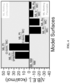
- FIG. 4 is a graph depicting a theoretical study of the NM probability to wet various surfaces depicting the difference in B.E.s for NM ML formation on various model surfaces relative to the B.E. on native NM surfaces.
- FIG. 5 is a graph depicting PXRD Diffractograms of SiO 2 /Pt/Ti 0.02 W 0.98 C after carburization (blue) and before carburization if the material is instead calcined in air at 400° C. (red).
- FIG. 6 is a graph depicting W 4f, Pt 4f, and C 1s XPS signals for nanopowders of Pt/(Ni 0.2 W 0.8 ) 2 C and Pt/Ti 0.06 W 0.94 C.
- FIG. 7 is an image depicting ML Pt/Ti 0.1 W 0.9 C NPs dispersed at ⁇ 20 wt % on Vulcan® XC-72r carbon black.
- FIGS. 8 A- 8 G show experimental corroboration of core-shell structure.
- FIGS. 8 A- 8 B are STEM images and EDS maps of carbon-supported 26% Pt/74% Cu 0.2 W 0.8 C 0.5 NPs ( FIG. 8 A ) and 27% PtRu (2:1)/73% Ti 0.1 W 0.9 C (denoted as PtRu C-S ) ( FIG. 8 B ).
- FIG. 8 C shows PXRD diffractograms of silica-encapsulated NM/TMC NPs of various sizes, compositions, and NM ML coverages.
- FIG. 8 A- 8 B are STEM images and EDS maps of carbon-supported 26% Pt/74% Cu 0.2 W 0.8 C 0.5 NPs ( FIG. 8 A ) and 27% PtRu (2:1)/73% Ti 0.1 W 0.9 C (denoted as PtRu C-S ) ( FIG. 8 B ).
- FIG. 8 C shows PXRD diffractograms of silica-encapsul
- FIG. 8 D shows XPS spectra of NM/TMC nanoaggregates showing sub-ML, ML, and multilayer coverages of (a-c) Au, (d-f) Pt, and (g, h) mixed Pt:Au shells self-assembled onto the surface of TiWC NPs.
- FIG. 8 E shows PXRDs of Pt C-S and Pt direct compared to Pt comm .
- FIG. 8 F shows XPS comparison of the C 1s, Pt 4f, and W 4f signals of Pt C-S and Pt direct .
- FIG. 8 G shows TEM and HR-TEM images of Pt C-S , PtRu C-S , and Pt direct .
- Pt C-S consists of 28% Pt/72% Ti 0.1 W 0.9 C NPs dispersed on carbon black at 28 wt % prepared by silica encapsulation and removal.
- FIGS. 9 A- 9 G show electrochemical activity and stability of Pt C-S and PtRu C-S compared to commercial catalysts.
- FIG. 9 A shows CVs showing different H upd and OH ad surface coverages.
- For PtRu C-S CO-stripping voltammograms are shown before and after stability cycling and regeneration.
- FIG. 9 B shows HOR/HER Tafel plots.
- FIG. 9 C shows HOR LSVs with and without CO contamination.
- FIG. 9 D shows MOR CVs at 50 mV/s normalized by CO-ECSA. The inset displays LSVs at 10 mV/s.
- FIGS. 9 E and 9 F Steady-state specific activity and mass activity at fixed potentials after stability cycling and regeneration in alkaline media.
- FIG. 9 G shows TEM images of Pt C-S and PtRu C-S and a STEM image with EDX map of a Pt C-S nanoparticle after stability cycling.
- FIGS. 10 A- 10 F show comparison of core-shell Pt/TiWC/C NPs obtained via the silica-encapsulation and removal method vs. Pt/TiWC/C prepared by directly carburizing carbon-supported (NH 4 ) 2 PtCl 6 /TiWO x NPs.
- FIGS. 11 A- 11 B show structural changes in SiO 2 /(NH 4 ) 2 PtCl 6 /WO x system during carburization.
- FIG. 11 A shows EDX map of SiO 2 /Pt/WO x heat-treated to 200° C. in a 15% CH 4 /H 2 atmosphere corresponding to FIG. 1 B (ii).
- FIG. 11 B shows EDX map of SiO 2 /Pt x W y heat-treated to 600° C. in a 15% CH 4 /H 2 atmosphere corresponding to FIG. 1 B (iii).
- FIG. 12 shows a PXRD study of the core-shell NP self-assembly process during carburization.
- FIGS. 13 A- 13 B show Microscopic analysis of the core-shell NM/TMC nanodispersion.
- FIG. 13 A shows a representative TEM image of a NM/TMC nanoaggregate dispersed in ethanol obtained by dissolving the silica shell without adding either a catalyst support or a surfactant capping agent.
- FIG. 13 B shows a representative TEM image of NM/TMC NPs dispersed in ethanol using oleylamine as a capping agent after removal of the silica template.
- FIG. 14 shows core-shell NP design space.
- FIGS. 15 A- 15 I show TEM analysis of NPs with varying shell composition encapsulated in silica.
- FIGS. 16 A- 16 I show TEM analysis of NPs with varying shell composition supported on carbon.
- FIG. 17 shows PXRD diffractograms of NM/TMC core-shell NPs where the TMC core is crystallized in a semicarbide lattice.
- FIGS. 18 A- 18 F show microscopic analysis of NPs with varying core compositions.
- FIG. 18 A shows STEM-EDX maps of 26% Pt/(Cu 0.2 W 0.8 ) 2 C from FIG. 8 A .
- FIGS. 18 B and 18 C show the corresponding TEM images of the material supported on carbon black.
- FIGS. 18 D and 18 E show TEM images of 23% Pt/(Co 0.2 W 0.8 ) 2 C supported on carbon black.
- FIG. 18 F shows STEM-EDX maps of 16% Pt/(Ni 0.3 W 0.7 ) 2 C supported on carbon black. The PXRD patterns of these materials are shown in FIG. 8 C .
- FIGS. 19 A- 19 D show XPS analysis of Pt C-S .
- FIG. 19 A shows raw XPS intensity data obtained for 28% Pt/72% Ti 0.1 W 0.9 C core-shell NP nanoaggregates (Pt C-S formulated as a nanoaggregate in ethanol without carbon black support added during silica removal to obtain clear C 1s spectrum).
- FIG. 19 B shows XPS peak deconvolution of the W 4f spectrum.
- FIG. 19 C shows XPS peak deconvolution of the C 1s spectrum.
- FIG. 19 D shows XPS peak deconvolution of the Pt 4f spectrum.
- FIGS. 20 A- 20 D show XPS analysis of PtRu C-S .
- FIG. 20 A shows raw XPS intensity data obtained for 27% Pt 0.67 Ru 0.33 /73% Ti 0.1 W 0.9 C core-shell NP nanoaggregates (PtRu C-S formulated as a nanoaggregate in ethanol without carbon black support added during silica removal to obtain clear C 1s spectrum).
- FIG. 20 B shows XPS peak deconvolution of the W 4f spectrum.
- FIG. 20 C shows XPS peak deconvolution of the C 1s and Ru 3d spectrum.
- FIG. 20 D shows XPS peak deconvolution of the Pt 4f spectrum.
- FIGS. 21 A- 21 D show XPS analysis of PtRh/TiWC NPs.
- FIG. 21 A shows raw XPS intensity data obtained for 26% Pt 0.6 Rh 0.4 /74% Ti 0.1 W 0.9 C core-shell NP nanoaggregates.
- FIG. 21 B shows XPS peak deconvolution of the W 4f spectrum.
- FIG. 21 C shows XPS peak deconvolution of the Rh 3d spectrum.
- FIG. 21 D shows XPS peak deconvolution of the Pt 4f spectrum.
- FIGS. 22 A- 22 D show XPS analysis of PtIr/TiWC NPs.
- FIG. 22 A shows raw XPS intensity data obtained for 25% Pt 0.8 Ir 0.2 /75% Ti 0.2 W 0.8 C core-shell NP nanoaggregates.
- FIG. 22 B shows XPS peak deconvolution of the W 4f spectrum.
- FIG. 22 C shows XPS peak deconvolution of the Ir 4f spectrum.
- FIG. 22 D shows XPS peak deconvolution of the Pt 4f spectrum.
- FIGS. 23 A- 23 D show XPS analysis of Au/TiWC NPs.
- FIG. 23 A shows raw XPS intensity data obtained for 13% Au/Ti 0.1 W 0.9 C core-shell NP nanoaggregates.
- FIG. 23 B shows XPS peak deconvolution of the W 4f spectrum.
- FIG. 23 C shows XPS peak deconvolution of the Ti 2p spectrum.
- FIG. 23 D shows XPS peak deconvolution of the Au 4f spectrum.
- FIGS. 24 A- 24 D show XPS analysis of Pt/CuWC NPs.
- FIG. 24 A shows raw XPS intensity data obtained for 26% Pt/(Cu 0.2 W 0.8 ) 2 C core-shell NP nanoaggregates.
- FIG. 24 B shows XPS peak deconvolution of the W 4f spectrum.
- FIG. 24 C shows XPS peak deconvolution of the Cu 2p spectrum.
- FIG. 24 D shows XPS peak deconvolution of the Pt 4f spectrum.
- FIGS. 25 A- 25 E shows characterization of commercial Pt comm and PtRu comm catalysts. Wide-view TEM and HR-TEM images of (A,C) Pt comm and (B,D) PtRu comm . (E) PXRD patterns of Pt comm and PtRu comm .
- FIGS. 26 A-F show CO stripping voltammograms for various catalysts and controls.
- FIG. 27 shows post-conditioning CVs for various catalysts and controls.
- FIGS. 28 A- 28 D show HOR and HER activity analysis.
- FIGS. 29 A- 29 B show CO electrooxidation activity: LSVs with iR compensation showing geometric current densities ( FIG. 29 A ) and specific activities ( FIG. 29 B ) for various catalysts.
- FIGS. 30 A- 30 D show MOR Initial Activity Comparison and Reproducibility Study.
- FIGS. 31 A- 31 F show detailed analysis of PtRu C-S performance for MOR.
- FIG. 32 shows microscopic evidence of Pt C-S stability after cycling.
- FIGS. 33 A- 33 F show microscopic analysis of Pt sub-ML after various heat treatments.
- FIGS. 34 A- 34 B show PXRD analysis of Pt comm and Pt sub-ML after various heat treatments.
- FIGS. 35 A- 35 B show impact of various heat treatments on the PSDs of Pt comm and Pt sub-ML .
- FIG. 36 shows PXRD comparison between Pt C-S and PtRu C-S .
- FIG. 37 shows model surfaces obtained from high temperature DFT equilibration.
- FIG. 38 shows elemental projected density of states aligned to the vacuum level.
- FIGS. 39 A- 39 B show a comparison of Pt d-band centers from projected density of states.
- FIGS. 40 A- 40 D show MOR Stability Study.
- FIG. 40 A shows PtRu C-S compared to PtRu comm on a specific activity basis ( FIG. 9 E ).
- FIG. 40 B shows PtRu C-S compared to PtRu comm on a mass activity basis.
- FIG. 40 C shows Pt C-S compared to Pt comm on a specific activity basis.
- FIG. 40 D shows Pt C-S compared to Pt comm on a mass activity basis.
- FIG. 41 shows XPS analysis of Pt sub-ML after various heat treatments.
- FIGS. 42 A- 42 D show experimental exploration of various core-shell NM/TMC architectures.
- FIG. 42 A shows PXRD diffractograms of NM/TiWC nanoparticles of various sizes, compositions, and NM coverages.
- FIG. 42 B shows STEM image and EDX maps of carbon-supported Pt/(CuW) 2 C nanoparticles.
- FIG. 42 C shows PXRD diffractograms of Pt monolayers on various bimetallic semicarbide core nanoparticles.
- FIG. 42 A shows PXRD diffractograms of
- 42 D shows XPS spectra of (a-c) Au/TiWC nanoparticles, (d-f) Pt/TiWC nanoparticles, and (g,h) PtAu/TiWC nanoparticles with sub-monolayer, monolayer, and multilayer NM shell thicknesses.
- FIGS. 43 A- 43 F show transmission electron micrographs of carbon-supported TiWC ( FIG. 43 A ), ⁇ 0.01 ML Pt/TiWC ( FIG. 43 B ), 0.05 ML Pt/TiWC ( FIG. 43 C ), 0.25 ML Pt/TiWC ( FIG. 43 D ) and 2 ML Pt/TiWC ( FIG. 43 E ).
- the scale bar shown in FIG. 43 A applies to all micrographs from FIG. 43 A to FIG. 43 E .
- FIG. 43 F shows scanning electron micrograph (SEM) of 2 ML Pt/TiWC.
- FIGS. 44 A- 44 B show x-ray diffraction patterns of supported catalysts and representative XPS spectra of nanodispersions after silica dissolution for W and Pt signals.
- FIGS. 45 A- 45 D show LSVs ( FIGS. 45 A and 45 B ) and Tafel plots ( FIGS. 45 C and 45 D ) obtained for supported catalysts in 1.0 M HClO 4 at 10 mV s ⁇ 1 at 30° C.
- the legend shown in FIG. 45 A applies to FIGS. 45 B- 45 C . All materials were loaded at the same total mass per geometric surface area (255 ⁇ g cat cm ⁇ 2 geo ); the masses listed in FIG. 45 A refer to the geometric Pt mass loadings for each catalyst and apply to FIGS. 45 B- 45 D .
- FIG. 46 A shows Tafel plots and their fits to the Butler-Volmer equation obtained in 1.0 M HClO 4 at 10 mV s ⁇ 1 at 30° C.
- FIG. 46 B shows exchange current density (j 0 ) derived from the fits vs. Pt loading for supported catalyst.
- FIGS. 47 A- 47 B show LSVs ( FIG. 47 A ) and plot of log(j 0 ) vs 1000/T ( FIG. 47 B ) obtained for 0.25 ML Pt/TiWC catalyst in 1.0 M HClO 4 at 10 mV s ⁇ 1 at varying temperatures (10-40° C.).
- FIG. 48 shows the effect of Pt coverage ( ⁇ Pt ) on the HER activity of core-shell Pt/TiWC supported catalysts used in this work in comparison with the WC thin film study reported previously in D.V. Esposito, et al. Angew. Chem. Int. Ed., 2010, 49, 9859.
- FIG. 49 A shows LSVs obtained for 0.25 ML Pt/TiWC catalyst in 1.0 M HClO 4 at 10 mV s ⁇ 1 at 30° C. before and after cycling and chronopotentiometry studies. The initial activity LSVs were averaged over 5 replicate electrode mountings.
- FIG. 49 B shows chronopotentiometry studies for 0.25 ML Pt/TiWC catalyst involving over 140,000 turnovers on a mol H2 mol ⁇ 1 Pt basis. Cycling conditions: 10,000 cycles at 100 mV s ⁇ 1 from ⁇ 50 mV to 600 mV in 1.0 M HClO 4 . Chronopotentiometry conditions: +5 mA cm ⁇ 2 geo for 15 min followed by ⁇ 5 mA cm ⁇ 2 geo for 15 min for 16 h, uncompensated.
- FIG. 50 shows a technoeconomic comparison of earth-abundant CoP catalyst with Pt-containing catalysts expressed as HER cathode catalyst lifetime cost vs. Pt loading. Error bars represent prediction intervals with 95% confidence.
- FIG. 51 shows a technoeconomic comparison of earth-abundant CoP catalyst with Pt-containing catalysts expressed as HOR anode lifetime cost vs. Pt loading. Error bars represent prediction intervals with 95% confidence.
- NMs noble metals
- the noble metals are nature's universal catalysts. By neither binding reactants too strongly nor too weakly, they are able to efficiently insert or remove electron density from reactants with high turnover numbers. As such, they have been shown to be the best catalysts in almost all industrially-relevant catalytic processes. Beyond catalysis, their chemical inertness and corrosion resistance is now being widely investigated in high resolution sensors and for biomedical applications involving nanoscale drug delivery mechanisms. See Marie-Christine Daniel, D. A. Gold Nanoparticles: Assembly, Supramolecular Chemistry, Quantum-Size-Related Properties, and Applications toward Biology, Catalysis, and Nanotechnology. Chem. Rev. 2004, 104, 293-346, which is incorporated by reference in its entirety.
- the NMs are formulated as high surface area nanomaterials. See Bell, A. T. The Impact of Nanoscience on Heterogeneous Catalysis. Science 2003, 299, 1688-1691, which is incorporated by reference in its entirety.
- the NM functionality persists only at the exposed surface, meaning that the majority of the NM atoms in the bulk are underutilized.
- Core-shell nanoparticles (NPs) with single monolayer (ML) shells of noble metals offer the opportunity to achieve the minimum required NM loadings across a broad spectrum of technologies.
- FIG. 1 A cut-away schematic diagram of a 5 nm ML core-shell nanoparticle (drawn to scale) is shown in FIG. 1 .
- TMX early transition metal ceramic
- carbon-supported Ti 0.1 W 0.9 C nanoparticles coated with Pt or bimetallic PtRu monolayers were found to exhibit enhanced resistance to sintering and CO poisoning, achieving an order of magnitude increase in specific activity over commercial catalysts for methanol electrooxidation after 10,000 cycles.
- These core-shell materials provide a new direction to reduce the loading, enhance the activity, and increase the stability of noble metal catalysts.
- This monolayer (ML) core-shell configuration enables every NM atom to participate in catalytic surface reactions, achieving the lowest possible limit for NM-utilization in a high surface area heterogeneous catalyst.
- NM/TMX core-shell NPs The scalable and solution-processable method used to generate these NM/TMX core-shell NPs is amenable to the production of multimetallic early TMX cores of tunable sizes with multimetallic NM shells of tunable thicknesses.
- ultra-low loading NM/TMX materials can achieve the required energy:cost ratio for use in PEM fuel cells, direct methanol and higher oxygenate fuel cells, electrolyzers, hybrid supercapacitors, and Li-Air batteries on a global scale.
- Core-shell nanoparticles comprised of atomically-thin NM monolayers (MLs) dispersed over a non-precious core have the potential to address these challenges if several rigorous requirements are met.
- the core should consist of earth-abundant, corrosion-resistant, and electrically conductive materials.
- the core must exhibit a high melting point, bind strongly to the NM shell, but remain insoluble in the NM lattice.
- the size and composition of both the core and the shell should be easily controlled.
- Transition metal carbides are attractive candidates for supporting NM shells because they satisfy each of the above core requirements.
- tungsten carbide a material at least three orders of magnitude less expensive than platinum (Pt) ( FIG. 2 ) with a “Pt-like” surface density of electronic states (DOS)—can host active Pt monolayers for many industrially relevant thermo- and electrochemical reactions.
- DOS electronic states
- FIG. 4 shows DFT study of the binding energies of noble metal monolayers (NM MLs) on various planar surfaces compared to the binding energies of NM MLs on native NM planar surfaces.
- ⁇ [B.E.ML NM/NM-B.E.ML NM/NM] (denoted as ⁇ [B.E.]) is greater than zero for a ML of Pt adsorbed on graphite, oxygen-terminated WC, and carbidic carbon-terminated WC. This predicts that it is less favorable for Pt to wet these surfaces in a ML fashion than to bind to itself.
- NM/TMC shell/core nanoparticles
- TMC synthesis typically requires carburizing at temperatures above 700° C. followed by dilute oxygen passivation, resulting in sintered particles covered in both graphitic coke and and/or an oxide surface layer. These surface impurities preclude NM wetting due to the unfavorable BEs between NMs and contaminated TMC surfaces ( FIG. 4 ). Consequently, rather than creating monolayer NM/TMC core-shell nanoparticles, post-synthetic methods, such as wet impregnation or atomic layer deposition, form discrete NM nanoparticles. See, Z. Yan, M. Cai, P. K. Shen, Sci. Rep. 3, 1646 (2013), and I. J. Hsu, Y. C. Kimmel, X. Jiang, B. G. Willis, J. G. Chen, Chemical Communications 48, 1063-1065 (2012), each of which is incorporated by reference in its entirety.
- the cores are either other noble metals, such as palladium and silver, or top row 3d transition metals, such as Ni. See, Sasaki, K. et al. Core-Protected Platinum Monolayer Shell High-Stability Electrocatalysts for Fuel-Cell Cathodes. Angew. Chem. Int. Ed. 2010, 49, 8602-8607, Sasaki, K. et al. Highly Stable Pt Monolayer on Pdau Nanoparticle Electrocatalysts for the Oxygen Reduction Reaction.
- NMs such as Pd and Ag are too expensive while Ni is unstable for catalytic reactions at high potentials or at high temperatures as it sinters and oxidizes readily.
- the NM surface shells are fully miscible in these core materials, making such core-shell NPs unsuitable for thermal catalysis at elevated temperatures.
- ML NM/TMX NPs stand to offer a new dimension on modifying the C, H, and O binding energies of reactants on NM surfaces to simultaneously optimize catalytic reaction pathways while also substantially reducing noble metal loadings.
- TMC nanoparticles ⁇ 10 nm coated with monometallic or heterometallic NM surface shells of controlled thicknesses ranging from sub-monolayer to multilayer coverages.
- These core-shell materials achieve superior catalytic activity, improved stability, and reduced NM loadings compared to state-of-the-art commercial catalysts for electrochemical applications.
- the overall synthetic strategy uses a reverse microemulsion (RME) to precipitate combinations of NM chloride salts with monometallic or heterometallic transition metal oxide (TMO) nanoparticles, achieving precise control over nanoparticle composition, size, and NM loading.
- RME reverse microemulsion
- the composite particles are then encapsulated in silica nanospheres prior to carburization. See, S. T. Hunt, T. Nimmanwudipong, Y. Roman-Leshkov, Angew. Chem. Int. Ed. Engl. 53, 5131-5136 (2014), which is incorporated by reference in its entirety.
- the ideal subsurface core must be composed of earth-abundant and inexpensive materials, exhibit corrosion-resistance, sinter-resistance, and electrochemical stability, exhibit metallic electrical conductivity, bind strongly to the surface noble metal ML, preferably stronger than the cohesive energy of the noble metal, exhibit electronic similarities to the noble metal ML to mitigate bimetallic ligand effects, exhibit similar lattice geometry to the noble metal ML to mitigate bimetallic lattice strain/compression effects.
- the NM shell must also be insoluble in the core lattice under reaction conditions.
- TMXs metallic early transition metal ceramics
- TMXs metallic early transition metal ceramics
- WC borides, carbides, nitrides, and phosphides of the Group IV-VI early transition metal d-block elements
- TMCs early transition metal carbides
- Mo 2 C molybdenum carbide
- FIGS. 2 A- 2 C show the inflation-adjusted monthly average prices for platinum-group metals as well as for reagent-grade APT powder.
- a scalable, solution-phase route of preparing size-tunable WC NPs that exhibit “Pt-like” catalytic activity has been recently disclosed. See, Hunt, S. T.; Nimmanwudipong, T.; Roman-Leshkov, Y. Engineering Non-Sintered, Metal-Terminated Tungsten Carbide Nanoparticles for Catalysis. Angew. Chem. Int. Ed. Engl. 2014, 53, 5131-5136, and Roman-Leshkov, Y.; Hunt, S. T.
- TMX materials can only be synthesized at high temperatures (greater than ca. 700° C.). This often leads to sintering and loss of surface area, but critically it leads to excess surface impurity deposition, such as graphitic carbon. See Kimmel, Y. C.; Esposito, D. V.; Birkmire, R. W.; Chen, J. G. Effect of Surface Carbon on the Hydrogen Evolution Reactivity of Tungsten Carbide (WC) and Pt-Modified WC Electrocatalysts. Int. J.
- TMX materials are irreversibly passivated with a stable oxide layer. See Weidman, M. C.; Esposito, D. V.; Hsu, I. J.; Chen, J. G. Electrochemical Stability of Tungsten and Tungsten Monocarbide (Wc) over Wide Ph and Potential Ranges. J. Electrochem. Soc. 2010, 157, F179, which is incorporated by reference in its entirety. On doping with NMs, core-shell NPs are not thermodynamically favorable. FIG.
- DFT density functional theory
- the method allows for the synthesis of both mono- and multi-metallic TMX NPs with tunable sizes and crystal phases. As such, this was the critical first step towards the ultimate goal of ML NM/TMX NPs.
- initial attempts at preparing ML NM/TMX NPs via post-modification were unsuccessful, ostensibly due to oxygen passivation in ambient conditions. Instead, a new and scalable procedure has been developed for producing ML NM/TMX NPs using the previously published and patented method without any additional processing steps.
- commercial NM salts are precipitated onto the surface of transition metal oxide NPs and encapsulated within silica nanospheres prior to carburization as shown in FIG. 4 .
- ML NM/TMX NPs self-assemble for the following reasons.
- the noble metals cannot form stable borides, carbides, nitrides, phosphides, etc. See, Ono, S.; Kikegawa, T.; Ohishi, Y. A High-Pressure and High-Temperature Synthesis of Platinum Carbide. Solid State Commun. 2005, 133, 55-59, which is incorporated by reference in its entirety. Therefore, on high temperature carburization, they remain phase-segregated from the crystallizing TMX NPs. Second, at these high temperatures, the formed WC NPs are in a reducing environment and are therefore metal-terminated without an oxide or graphitic carbon surface layer.
- the noble metals such as Pt
- the Pt does not bind strongly to the surface and remain as separate Pt NPs, which easily sinter.
- the silica nanospheres efficiently prevent sintering and ensure that each TMC NP is evenly and uniformly coated with similar amounts of noble metal.
- FIG. 4 shows a schematic of the original, three-step method for preparing non-sintered and metal-terminated TMX NPs as well as a new method for preparing ML NM/TMX NPs via high temperature self-assembly.
- a non-ionic commercial surfactant Brij® L4
- water are mixed together to form a reverse microemulsion (RME) consisting of water nanodroplets dispersed in oil.
- RME reverse microemulsion
- SiO 2 /NM/TMO silica-encapsulated noble metal/transition metal oxide
- the composite material is precipitated from the emulsion by addition of methanol and recovered via decantation.
- the material is then directly heated in a 15%/85% CH 4 /H 2 atmosphere at 900° C. for 4 hours.
- the silica-encapsulated noble metal/transition metal carbide (SiO 2 /NM/TMC) NPs are dispersed in a room-temperature ethanol solution for 18 hours with dilute HF added to it such that the molar ratio of HF:Si is 6:1.
- This solution is effectively 1 wt % HF initially and around 0.3 wt % HF once all of the SiO 2 is removed as SiF 4 .
- NM/TMC NPs which can then be stored as a nanodispersion, precipitated as a nanopowder, or dispersed on any desired high surface area catalytic support material, such as carbon black, graphene, carbon nanotubes, alumina, etc.
- FIG. 1 B shows aberration-corrected scanning transmission electron microscopy (STEM) images depicting the stages of the NM/TMC core-shell self-assembly process as a function of temperature using Pt/WC nanoparticle formation as a representative example.
- Discrete SiO 2 /(NH 4 ) 2 PtCl 6 /WO x nanoparticles (15 wt % metals basis in SiO 2 ) were prepared using the RME method and subjected to a temperature ramp under a 15% CH 4 /85% H 2 gas flow ( FIG. 1 B (i)).
- FIG. 12 shows PXRD diffractograms of as-synthesized SiO 2 /(NH 4 ) 2 PtCl 6 /WO x after heating to 200° C., 300° C., 600° C., and 900° C.
- EDX energy-dispersive X-ray spectroscopy
- the final architecture of the Pt/WC nanoparticles is controlled by the Pt:W and W:SiO 2 ratios of the SiO 2 /(NH 4 ) 2 PtCl 6 /WO x material prior to heating.
- the silica template can then be dissolved at room temperature, and the resulting nanoparticles can be dispersed in solution with or without a capping agent ( FIG. 13 ) or dispersed onto a high surface area matrix ( FIG. 1 B (v)).
- FIG. 13 A shows a representative TEM image of a NM/TMC nanoaggregate dispersed in ethanol obtained by dissolving the silica shells without adding either a catalyst support or a surfactant capping agent.
- the material is Pt/Ti 0.1 W 0.9 C core-shell NPs corresponding to Pt C-S and is typical of the material formulation used for XPS analysis of NM/TMC NPs.
- FIG. 13 B shows a representative TEM image of NM/TMC NPs dispersed in ethanol using oleylamine as a capping agent after removal of the silica template.
- the above material consists of PtRu(1:1)/Ti 0.1 W 0.9 C core-shell NPs.
- FIG. 5 shows powder x-ray (PXRD) diffractograms for SiO 2 /Pt/Ti 0.02 W 0.98 C after carburization (in blue) and before carburization if the material is heated in a CH 4 /H 2 atmosphere to 400° C. and then cooled.
- PXRD powder x-ray
- the nanopowder was then analyzed using X-ray Photoelectron Spectroscopy (XPS) to determine the surface composition, which is shown in FIG. 6 . If a core-shell configuration was achieved, the surface element would substantially screen the signal of the sub-surface elements, resulting in the atomic concentration being greater than the bulk molar composition determined using ICP-AES. See, Cumpson, P. J.; Seah, M. P. Elastic Scattering Corrections in Aes and Xps. Ii. Estimating Attenuation Lengths and Conditions Required for Their Valid Use in Overlayer/Substrate Experiments. Surf. Interface Anal. 1997, 25, 430-446, which is incorporated by reference in its entirety.
- XPS X-ray Photoelectron Spectroscopy
- the material composition was 80 mol % Pt, much greater than the bulk composition of 15 mol % determined using ICP-AES.
- the W 4f signal consists entirely of reduced metallic W without an observable surface passivating oxide, potentially indicating that the surface Pt ML is protecting the WC core, yielding a favorable and strong Pt—WC interaction.
- a carbidic C 1s signal was observed, indicating that the subsurface core is indeed carbidic.
- the Ni and Ti signals were nearly nonexistent, in agreement with other work performed on bimetallic TMC NPs that suggest these metals persist in a subsurface configuration even without a noble metal ML.
- FIGS. 8 E- 8 G compares two NM/TMC materials, one with silica encapsulation (denoted as Pt C-S , 28% Pt/72% Ti 0.1 W 0.9 C loaded at 28 wt % on carbon black), the other without silica encapsulation (denoted as Pt direct , 20% Pt/80% Ti 0.1 W 0.9 C loaded at 20 wt % on carbon black). Because TiC is the most electrochemically stable carbide (see, Y. C. Kimmel, X. Xu, W. Yu, X. Yang, J. G. Chen, ACS Catal.
- Silica encapsulation prevents undesirable coking during carburization, as verified by a 6-fold decrease in the carbon-to-metal surface ratio for Pt C-S compared to Pt direct ( FIG. 8 F ).
- Characteristic graphitic coke fibrils and sintered nanoparticles encapsulated in 4-5 nm of graphitic coke are visible in the transmission electron microscopy (TEM) images of Pt direct ( FIG. 8 G ).
- Pt direct consists of 28% Pt/72% Ti 0.1 W 0.9 C NPs dispersed on carbon black at 20 wt % and carburized directly on the carbon black support without using silica encapsulation and removal.
- Pt comm is 20 wt % Pt/C commercial catalyst supplied by Premetek® (Wilmington, DE).
- Pt C-S shows well-dispersed crystalline nanoparticles with a uniform particle size distribution (PSD) of 6-8 nm and the absence of detectable graphitic coke layers.
- PSD uniform particle size distribution
- a heterometallic 27% Pt 0.67 Ru 0.33 /73% Ti 0.1 W 0.9 C material (denoted as PtRu C-S ) was synthesized analogously to Pt C-S and exhibits similar physico-chemical properties ( FIGS. 8 G, 19 , 20 , and 36 ). Its core-shell structure is clearly visible on the aberration-corrected STEM-EDX map shown in FIG. 8 B .
- FIG. 36 PXRD patterns of Pt C-S and PtRu C-S show phase-pure fcc WC lattices without additional reflections associated with metallic Pt or Ru.
- 26 A-F show CO-stripping voltammograms of (A) Pt comm , (B) PtRu comm , (C) Pt C-S , (D) PtRu C-S , (E) Pt direct and carbon black, and (F) empty GC electrode, collected by holding the working electrode potentiostatically at +0.025 V vs. RHE in CO-saturated 0.1 M HClO 4 at 30° C. under a rotation rate of 1600 rpm followed by an Ar-purge and scanning at 50 mV/s with iR compensation.
- the reported CVs are the second scan obtained immediately after the first CO-stripping scan.
- CVs for Pt C-S and PtRu C-S exhibit high capacitance and characteristic peaks for hydrogen adsorption/desorption (H upd ) below 0.4 V, but with notable differences from Pt comm and PtRu comm .
- the characteristic region of OH adsorption/desorption (OH ad ) observed for Pt comm above 0.6 V is suppressed on both core-shell materials.
- the distinct pseudocapacitance of surface RuO x species is less pronounced on PtRuc C-S compared to PtRu comm .
- TiWC cores modulate the electrochemical behavior of Pt and PtRu, which was characterized further using density functional theory (DFT) and various probe reactions including hydrogen evolution (HER), hydrogen oxidation (HOR), HOR under CO contamination, and methanol electrooxidation (MOR).
- DFT density functional theory
- HER hydrogen evolution
- HOR hydrogen oxidation
- MOR methanol electrooxidation
- Electrochemical active surface areas of core-shell and commercial catalysts Electrochemical active surface areas determined from triplicate electrode mountings using CO-stripping voltammetry (CO-ECSA) and under- potentially deposited hydrogen (H upd -ECSA). The CO-ECSA/ H upd -ECSA ratio is also provided where appropriate. H upd -ECSA is not reported for PtRu comm as it is poorly defined for this material (see, E. C. Weigert, a. L. Stottlemyer, M. B. Zellner, J. G. Chen, J. Phys. Chem. C 111, 14617-14620 (2007), which is incorporated by reference in its entirety).
- FIG. 28 A shows raw LSV data collected for various catalysts before and after 10,000 potential cycles without iR compensation. These data were used to obtain the Tafel plots in FIG. 9 B .
- FIG. 28 B shows a Koutecky-Levich plot obtained from the LSVs shown in FIG. 28 A using the current densities at 0.5 V and various rotation rates. The theoretical line was constructed for a two-electron transfer process using a diffusion coefficient of 4.5 ⁇ 10 ⁇ 5 cm 2 /s, a solution viscosity of 0.008 cm 2 /s at 30° C., and a concentration of 7.2 ⁇ 10 ⁇ 7 mol H 2 /cm 3 electrolyte.
- FIG. 28 A shows raw LSV data collected for various catalysts before and after 10,000 potential cycles without iR compensation. These data were used to obtain the Tafel plots in FIG. 9 B .
- FIG. 28 B shows a Koutecky-Levich plot obtained from the LSVs shown in FIG. 28 A using the current densities at
- FIG. 28 C show Raw LSV data obtained for PtRu C-S at various rotation rates showing representative data for how instrument-applied iR compensation affects the shapes of the LSV curves during data acquisition.
- FIG. 28 D shows raw LSV data obtained at 1600 rpm for Pt C-S and PtRu C-S compared to empty Vulcan® XC-72r carbon black, an empty GC electrode, and Pt direct .
- the extensive coking and sintering suppresses both the HER and HOR activity of Pt direct in comparison with the core-shell materials prepared using silica encapsulation/removal.
- both core-shell materials exhibit a 4-fold improvement in specific activity and a 3-fold improvement in mass activity over the commercial catalysts (Table 3), and this enhancement is maintained after cycling.
- Enhanced catalytic activity is corroborated by DFT calculations for thermally equilibrated Pt/TiWC slabs. Specifically, it is shown that Fermi level matching causes minimal alterations to the workfunction of surface Pt by subsurface TiWC (see, W. Schottky, Annalen der Physik 362, 541-567 (1918), which is incorporated by reference in its entirety) ( FIGS.
- FIG. 37 shows the [111] terminated TiWC slab model with various surface concentrations of Pt. The structures shown are the result of the high temperature equilibrated ab initio molecular dynamics simulations on the slabs.
- FIG. 38 shows the elemental projected density of states (Fermi level depicted in dotted lines) for the materials examined herein. The rightmost DOS arise from the pure [111] and [110] surface terminated bulk Pt.
- the d-band center as obtained by the mean of the integral of the pDOS, is Morse-like: At low loading levels, the Pt acts highly localized and the d-band descriptor breaks down. At monolayer and greater loading the d-band center progresses to that of bulk [11] Pt. This downshift corresponds to a ca. 10 kcal/mol weaking in the CO binding energy (see, B. Hammer, Y. Morikawa, J. Norskov, Phys. Rev. Lett. 76, 2141-2144 (1996), which is incorporated by reference in its entirety), potentially making Pt C-S and PtRu C-S resistant to CO poisoning.
- HER activity determined using chronopotentiometry (CP) and chronoamperometry (CA).
- CP chronopotentiometry
- CA chronoamperometry
- the measurements performed in H 2 -saturated 0.1M HClO 4 at 30° C. under a rotation rate of 2500 rpm. Initial activities were averaged from triplicate electrode mountings.
- FIG. 29 shows LSVs with iR compensation showing geometric current densities ( FIG. 29 A ) and specific activities ( FIG. 29 B ) for various catalysts performing CO electrooxidation in CO-saturated 0.1 M HClO 4 at 30° C. and 2 mV/s under a rotation rate of 1600 rpm.
- the LSV current density at +0.4 V is improved by a factor of 8 for the NM/TMC core-shell materials relative to PtRu comm on a geometric basis and by a factor of 30 on a specific activity basis.
- the TiWC core is responsible for the enhanced MOR kinetics observed for PtRu C-S compared to PtRu comm , which display steady-state turnover frequencies (TOF) of 15.9 min ⁇ 1 and 3.6 min ⁇ 1 at 0.6 V, respectively (Table 4).
- the low onset potential (ca. 250 mV) for both PtRu C-S and PtRu comm originates in the bifunctional MOR mechanism, which is known to enhance the performance of PtRu materials compared to a monometallic Pt catalyst. See, T. J. Schmidt, H. A. Gasteiger, R. J. Behm, Electrochem. Commun. 1, 1-4 (1999), and A.
- FIG. 30 A shows LSVs with iR compensation normalized by geometric current density for the NM/TMC core-shell catalysts and commercial controls at 10 mV/s in 1 M MeOH and 0.1 M HClO 4 at 30° C. and 1000 rpm. Each catalyst ink was mounted on three separate electrodes to examine measurement reproducibility. The vertical line represents E 0 , the thermodynamic reversible potential for MOR, which is 0.02 V vs. RHE.
- FIG. 30 B shows the LSVs from FIG. 30 A with the triplicate runs averaged at each 1 mV interval. The line thickness includes standard deviation error bars. The inset panel is magnified to show differences in the onset potential for MOR.
- FIG. 30 C shows the LSVs from FIG.
- FIG. 30 B normalized by specific surface area determined from CO stripping. The errors in the specific surface area measurements are propagated with the errors from the triplicate runs.
- the inset panel is magnified to show differences in the onset potential for MOR.
- FIG. 30 D shows the LSVs from FIG. 30 B normalized by loaded NM mass with errors propagated.
- the inset panel is magnified to show differences in the onset potential for MOR.
- FIG. 40 shows Chronoamperometry studies held at fixed potentials for 15 min intervals in 1 M MeOH and 0.1 M HClO 4 at 30° C. and 1000 rpm (0.35, 0.4, and 0.45 V) or 2500 rpm (0.6 V). The final current density was averaged over the last 1 min of the measurement. Initial activity measurements were performed after conditioning cycles. The chronoamperometry measurements were repeated after performing 5,000 cycles from ⁇ 50 to 600 mV at 100 mV/s, after 10,000 cycles from ⁇ 50 to 600 mV at 100 mV/s, and after regeneration (dipping the electrode for 2 min in 0.1 M NaOH solution).
- TOF is given as mol CO 2 per mol of surface sites per minute.
- PtRu C-S also demonstrates enhanced stability compared to PtRu comm ( FIGS. 9 E, 31 and 40 ).
- PtRu comm loses more than 50% of its steady-state activity at 0.35 V, 0.4 V, and 0.45 V, whereas PtRu C-S decreases by only 35% at these potentials and actually improves at 0.6 V.
- a simple 2 min alkaline dip partially regenerated the activity of PtRu C-S at all potentials, but had no appreciable benefit for PtRu comm .
- the overall loss in activity at low potentials for PtRu C-S was 20%.
- the final TOF at 0.6 V after 10,000 cycles and regeneration was 25.7 min ⁇ 1 for PtRu C-S and 2.3 min ⁇ 1 for PtRu comm , representing an order of magnitude improvement of our core-shell material over the commercial catalyst.
- FIG. 31 All measurements were performed in 1 M MeOH and 0.1 M HClO 4 at 30° C. under a rotation rate of 1000 rpm with iR compensation applied.
- FIG. 31 A shows initial activity CA curves at 0.35 V for triplicate mountings.
- FIG. 31 B shows initial activity reproducibility study obtained from averaging the current response over the last minute of CA data collected for 15 min for triplicate electrode mountings. Representative raw CA data is shown in FIG. 31 A .
- FIG. 31 C shows representative CA data collected at 0.35 V over 15 min before, during, and after stability cycling as well as regeneration. The background current is obtained in the absence of MeOH. Data averaged over the last minute at various potentials are presented in FIG. 9 E- 9 G .
- FIG. 9 E- 9 G Data averaged over the last minute at various potentials are presented in FIG. 9 E- 9 G .
- FIG. 31 D shows after 10,000 cycles and regeneration in alkaline media, PtRu C-S maintains a positive current density even at the low potential of 0.25 V over 30 min, while it did not exhibit any activity at 0.25 V before stability cycling (data not shown).
- FIG. 31 E shows LSVs at 10 mV/s before, during, and after stability cycling as well as regeneration.
- FIG. 31 F shows a magnified version of panel FIG. 31 E showing the onset potential for MOR.
- FIG. 9 G shows HR-STEM and EDX mapping of Pt C-S after stability cycling from ⁇ 50 mV to 600 mV. The individual Pt, W, and Ti maps are shown as well as an overlay of all three elements and an overlay of just Pt and W.
- the improved stability of the core-shell materials is attributed both to the predicted strong binding of the NM shell to the metal-terminated WC surface and to the lower surface free energies of large nanoparticles relative to the surface free energies of ultrasmall nanoparticles. See, E. F. Holby, W. Sheng, Y. Shao-Horn, D. Morgan, Energy Environ. Sci. 2, 865 (2009), which is incorporated by reference in its entirety.
- the high temperature self-assembly process employed here is general and permits comprehensive control of the entire core-shell architecture for a variety of early and late transition metals ( FIG. 42 ).
- TiWC cores we successfully synthesized nanoparticles with varying sizes (3-10 nm), mono- and bimetallic shell compositions (Ru, Rh, Ir, Pt, and Au), and NM coverages (ca. 0.5-3 ML) ( FIGS. 14 - 16 and 42 A ).
- FIG. 14 shows atomic ratio of surface ML coverage to the total number of metal atoms in the NP versus total NP diameter.
- Small core-shell NPs with sub-ML NM surface coverages offer complete NM dispersion while also offering bifunctional surfaces with exposed NM sites and TMC sites accessible for catalytic transformations.
- small core-shell NPs with complete ML NM coatings cannot offer substantial NM loading reductions. As such, this regime is designated as “Sub-ML Efficient.”
- complete MIL and multilayer NM surface coverages can still result in substantial reductions in NM loadings and are more appropriate for applications in electrocatalysis where durability is a significant challenge. As such, this regime is designated as “MIL Efficient.”
- This figure can also be used to estimate the regime of MIL coverage for various NM/TMC core-shell NPs synthesized using the new method reported here.
- a 4 nm core-shell NP consisting of 7% NM and 93% TMC (metals basis) has ⁇ 0.5 ML NM surface coverage.
- a 4 nm NP consisting of 13% NM and 87% TMC has ⁇ 1 ML NM surface coverage, while a 6 nm NP consisting of 22% NM and 82% TMC has ⁇ 2 ML NM surface coverage.
- An 8 nm NP consisting of 30% NM and 70% TMC has ⁇ 3 ML NM surface coverage.
- FIGS. 15 A- 15 I show TEM images for a representative selection of different NM/TMC core-shell NPs encapsulated in silica after carburization at 900° C. in a 15% CH 4 /85% H 2 atmosphere. All percentages are based on total metals basis as determined by ICP; (A) 6.1 ⁇ 0.9 nm 26% Pt 0.6 Rh 0.4 /74% Ti 0.1 W 0.9 C, (B) 6.4 ⁇ 1.0 nm 27% Pt 0.5 Ru 0.5 /73% Ti 0.1 W 0.9 C, (C) 5.7 ⁇ 1.1 nm 25% Pt 0.8 Ir 0.2 /75% Ti 0.2 W 0.8 C, (D) 6.1 ⁇ 1.0 nm 17% N 0.93 Au 0.07 /83% Ti 0.1 W 0.9 C, (E) 9.7 ⁇ 2.0 nm 27% Pt 0.7 Au 0.3 /73% Ti 0.2 W 0.8 C, (F) 7.7 ⁇ 1.4 nm 28% Pt/72% Ti 0.1 W 0.9 C (Pt C
- FIG. 16 A- 16 I show TEM images for a representative selection of different NM/TMC core-shell NPs supported on Vulcan® XC-72r carbon black after removal of the silica template;
- A 7.7 ⁇ 1.4 nm 28% Pt/72% Ti 0.1 W 0.9 C NPs supported on carbon (Pt C-S ),
- B 7.1 ⁇ 1.4 nm 21% Pt/79% Ti 0.1 W 0.9 C NPs supported on carbon,
- C 2.9 ⁇ 0.6 nm 13% Au/87% Ti 0.1 W 0.9 C NPs supported on carbon,
- D 6.1 ⁇ 0.9 nm 26% Pt 0.6 Ru 0.4 /74% Ti 0.1 W 0.9 C NPs supported on carbon
- E 5.7 ⁇ 1.1 nm 25% Pt 0.8 Ir 0.2 /75% Ti 0.2 W 0.8 C NPs supported on carbon
- F 6.1 ⁇ 1.0 nm 17% N 0.93 Au 0.07 /83% Ti 0.1 W 0.9 C NPs supported on carbon,
- FIG. 23 C shows XPS peak deconvolution of the Ti 2p spectrum.
- the Ti 2p spectrum is difficult to deconvolute for three reasons: the atomic sensitivity factor is low for ejected Ti 2p photoelectrons, the Ti concentration is low in the carbide cores, and the Ti signal is screened by the overlayer of noble metals. For these reasons, the Ti 2p spectrum for Pt 0.8 Ir 0.2 /Ti 0.2 W 0.8 C is shown. This a representative core-shell material with a higher core percentage of Ti. In cases where the core percentage is 10%, a deconvolution cannot be performed and instead an estimate of the Ti composition is obtained from simple integration as shown for the Ti 2p spectrum for Au/Ti 0.1 W 0.9 C.
- NM shells self-assemble onto bimetallic semicarbide cores such as (Cu 0.2 W 0.8 ) 2 C, (Co 0.2 W 0.8 ) 2 C, and (Ni 0.3 W 0.7 ) 2 C.
- the PXRD patterns of these core materials are representative of phase-pure semicarbide lattices (PDF #00-020-1315) ( FIG. 42 C ), and STEM-EDX mapping of Pt/(Cu 0.2 W 0.8 ) 2 C nanoparticles shows distinct Pt shells ( FIGS. 18 and 42 B ).
- the respective Pt:CuW ratios measured by XPS and ICP were 52% and 26%, respectively ( FIG. 24 ).
- the RME method also allows control of the NM shell thickness from sub-monolayer (ca. 0.5 ML) to multilayer (ca. 3 ML) coverages for mono- and heterometallic systems ( FIG. 42 D ).
- the XPS-determined surface NM:TiW ratio was higher than the ICP-determined bulk NM:TiW ratio.
- the extent of this surface ratio enhancement correlates with the monolayer coverage, ranging from 1-3% at sub-monolayer coverages to 10-20% at multilayer coverages (Table 5).
- the surface of Pt is well-known to passivate with a PtO layer, which is detectable as Pt 2+ with XPS.
- TMC nanoparticles coated with NM monolayers offer new, highly tunable pathways for decreasing NM loading requirements while increasing activity and stability in thermal and electrocatalysis.
- FIG. 33 shows TEM images of 20 wt % carbon-supported 4% Pt/96% Ti 0.1 W 0.9 C NPs (denoted as Pt subML ) after various heat treatments in different atmospheres.
- FIG. 34 shows PXRD diffractograms of Pt comm ( FIG. 34 A ) and Pt sub-ML ( FIG. 34 B ) heated to 400 or 600° C. in different atmospheres (H 2 , dry and wet N 2 flow) for 4 or 20 h.
- FIG. 35 shows Volume-weighted particle size distribution (PSD) plots for Pt comm ( FIG. 35 A ) and Pt sub-ML ( FIG. 35 B ) after various heat treatments in different atmospheres. Note that the x-axis varies from 0 to 40 nm in FIG. 35 A and from 0 to 10 nm in FIG. 35 B .
- PSDs were determined from at least 200 nanoparticles from several images taken across the TEM grids.
- FIG. 41 shows XPS study of the thermal stability of Pt sub-ML held in various atmospheres for 4 or 20 h and then passivated at room temperature. The percentages shown correspond to the XPS-determined Pt:W ratios. The ICP-determined bulk Pt:W ratio was 5%.
- nanoparticles comprising a transition metal oxide core and a noble metal shell can be transformed into nanoparticles comprising a core including transition metal carbide, transition metal nitride, transition metal boride, transition metal sulfide, or transition metal phosphide, by carrying out the transformation in an immobilizing matrix, such as an inert inorganic matrix, for example, silica, alumina, germania, zirconia, or ceria.
- an immobilizing matrix such as an inert inorganic matrix, for example, silica, alumina, germania, zirconia, or ceria.
- a three-step method that allows for the production of non-sintered, surface impurity-free, ultrasmall nanoparticles including a core including transition metal carbide, nitride, sulfide, boride or phosphide that can be highly loaded onto a desired support is disclosed.
- transition metal oxide nanoparticles can be encapsulated at room temperature within an inorganic matrix.
- the encapsulated transition metal oxide core of the nanoparticles can then be transformed to transition metal carbide, nitride, sulfide, boride or phosphide nanoparticles, for example, by carburization, nitridization, phosphorization, boridization or sulfidization in an appropriate atmosphere.
- the inorganic matrix can be removed, for example, by room-temperature dissolution, to yield either a nanodispersion of nanoparticles or supported nanoparticles.
- Nanoparticles can have a core/shell structure where the core includes a transition metal carbide, transition metal nitride or transition metal phosphide.
- the transition metal carbide can be a pure carbide or a mixed carbide, for example, a transition metal oxy carbide.
- Oxycarbides can be synthesized with any bulk carbon:oxygen stoichiometry. At low bulk oxygen concentrations, the tungsten moieties can be oxidized by oxygen without oxidation of the intercalated carbon moieties.
- These compositions can be prepared by exposing a carbide to an oxidizing atmosphere at elevated temperatures over long time periods.
- High bulk oxygen concentrations are typical for incompletely oxidized carbide materials in which local domains of tungsten moieties are oxidized with complete oxidation and removal of carbon via carbon dioxide release. Other localized moieties are incompletely oxidized and still contain intercalated carbons, giving an overall bulk carbon content that is low.
- Such materials are typically not isotropic and can be prepared by rapid heating and cooling in an oxidizing atmosphere via a furnace, a microwave, or using localized electric arc-based methods in a liquid environment.
- the transition metal nitride can be a pure nitride or a mixed nitride, for example, a transition metal oxy nitride.
- the transition metal phosphide can be a pure phosphide or a mixed phosphide, for example, a transition metal oxy phosphide.
- the transition metal carbide can be titanium carbide, zirconium carbide, hafnium carbide, vanadium carbide, niobium carbide, tantalum carbide, chromium carbide, molybdenum carbide, tungsten carbide, titanium oxy carbide, zirconium oxy carbide, hafnium oxy carbide, vanadium oxy carbide, niobium oxy carbide, tantalum oxy carbide, chromium oxy carbide, molybdenum oxy carbide, or tungsten oxy carbide.
- the transition metal nitride can be titanium nitride, zirconium nitride, hafnium nitride, vanadium nitride, niobium nitride, tantalum nitride, chromium nitride, molybdenum nitride, tungsten nitride, titanium oxy nitride, zirconium oxy nitride, hafnium oxy nitride, vanadium oxy nitride, niobium oxy nitride, tantalum oxy nitride, chromium oxy nitride, molybdenum oxy nitride or tungsten oxy nitride.
- the transition metal phosphide can be titanium phosphide, zirconium phosphide, hafnium phosphide, vanadium phosphide, niobium phosphide, tantalum phosphide, chromium phosphide, molybdenum phosphide, tungsten phosphide, titanium oxy phosphide, zirconium oxy phosphide, hafnium oxy phosphide, vanadium oxy phosphide, niobium oxy phosphide, tantalum oxy phosphide, chromium oxy phosphide, molybdenum oxy phosphide or tungsten oxy phosphide.
- the inorganic matrix can be alumina, silica, germania, zirconia, or ceria.
- the synthesized materials can include carbides, nitrides, or phosphides of Group III (scandium, yttrium, or lutetium, but not including lawrencium), and all 3d transition metals including scandium, yttrium, vanadium, chromium, manganese, iron, cobalt, nickel, copper, or zinc. While the platinum group metals, rhenium and technetium can form carbides and nitrides, the synthesis would require conversion at high pressures and temperatures (e.g., ⁇ 2000K), conditions in which any known inorganic matrices would have near zero porosity, meaning the method as described herein would not work unless other matrix materials were developed that could support pores at the conversion temperatures.
- Group III scandium, yttrium, or lutetium, but not including lawrencium
- All 3d transition metals including scandium, yttrium, vanadium, chromium, manganese, iron, cobalt, nickel
- F-block metals can also be used to make the materials described wherein, but these can be rare and have limited application.
- the notable exceptions are carbides, nitrides, and phosphides of lanthanum, cerium, neodymium or samarium.
- all of the lanthanides form stable carbides, nitrides, and phosphides at low temperatures, making them amenable to the removable ceramic coating method described herein.
- Neodymium is as abundant as nickel and iron in the earth's crust and its carbides, nitrides, and phosphides form at low temperature and have interesting optical and magnetic properties.
- Samarium phosphide is a unique small-band gap n-type semiconductor. The method could theoretically allow for the synthesis of ultrasmall samarium phosphide nanoparticles as this can be done below 1000 centigrade.
- Samarium isopropoxide is a commercially available and inexpensive.
- the core of the nanoparticle can have a composition of formula (I) M1 x M2 y M3 z X1 w1 X2 w2 (I)
- the size of such nanoparticle can be less than 20 nm, less than 10 nm, less than 5 nm, less than 3 nm or less than 1 nm.
- the nanoparticles with a metal oxide or metal core and a noble metal shell can be encapsulated in the inorganic matrix, reduced to a metal in a reducing atmosphere, and then carburized, nitridized, sulfidized, or phosphidized.
- the metal oxide core can be reduced to metal in a carburizing atmosphere, such as a methane/hydrogen atmosphere, a carbon monoxide-based atmosphere, an ethane-based atmosphere, etc. and further carburized to metal carbides.
- metal oxide core can be nitridized in a nitridizing atmosphere, such as an ammonia-based atmosphere.
- metal oxide core can be phosphidized in a phosphidizing atmosphere, such as a phosphine-based atmosphere.
- metal oxide core can be phosphidized by mixing one reverse microemulsion with ammonium metatungstate (AMT) and a second reverse microemulsion with ammonium phosphate to make ammonium phosphotungstate, coating directly with an inorganic matrix in-situ, calcining at to make/transition metal oxide nanoparticles in the inorganic matrix, and reducing to make transition metal phosphide nanoparticles in the inorganic matrix.
- Transition metal boride core can also be prepared similarly by flowing diborane gas.
- Transition metal boride core can also exist for most of the d-block metals, including W and Ni.
- Nickel boride is a hydrogenation catalyst and is also ferromagnetic.
- the inorganic matrix can be removed, as necessary.
- the cores including transition metal carbonitrides, carbophosphides, or nitrophosphides can also be synthesized in appropriate conditions.
- the inorganic matrix can include ceramics, silicates, glasses, aluminum silicates, alkali aluminum silicates, potassium silicates, sodium silicates, silicon carbides, silicon nitrides, cementitious materials, titanium oxides, aluminum oxides, magnesium oxides, boron oxides, phosphorus oxides, germanium oxides, indium oxides, tin oxides, zirconium oxides, cerium oxides or other matrix materials.
- the percentage of the transition metal can be greater than 1%, greater than 10%, greater than 20%, greater than 30%, or great than 40% in the inorganic matrix.
- the inorganic coating matrix can be made by, for example, one of the following methods.
- the inorganic matrix can be made by wet chemical methods using a matrix precursor, or by atomic layer deposition.
- an alumina layer can be created with Atomic Layer Deposition using trimethyl aluminum and water.
- a uniform 8 nm coating of alumina was obtained on a WO 3 /Al 2 O 3 sample.
- the material can then be reduced and carburized to form Al 2 O 3 / ⁇ -WC/Al 2 O 3 .
- the WO 3 can initially be supported on other catalysts as well such as titania, ceria, silica, zirconia, or zeolites such as ZSM-5.
- inorganic oxide overlayers can be prepared from other standard ALD precursors, such as tris(cyclopentadienyl)cerium, tetrakis(dimenthylamino)hafnium, silicon(IV) chloride, tetrakis(dimethylamino)titanium(IV), or tetrakis(dimethylamino)zirconium(IV).
- standard ALD precursors such as tris(cyclopentadienyl)cerium, tetrakis(dimenthylamino)hafnium, silicon(IV) chloride, tetrakis(dimethylamino)titanium(IV), or tetrakis(dimethylamino)zirconium(IV).
- Matrix precursors can be selected from a metal oxide precursors, such as a metal halide or alkoxide, titanium alkoxide, an aluminum alkoxide, a silicon alkoxide, a magnesium alkoxide, a boron alkoxide, a phosphorus alkoxide, a germanium alkoxide, an indium alkoxide, a tin alkoxide, a zirconium alkoxide, or mixtures thereof.
- the metal oxide precursor can be obtained commercially or prepared by contacting a metal halide with an alcohol. The precursor can then be formed into an inorganic matrix through controlled hydrolysis.
- the inorganic matrix is itself a metal oxide, and therefore all of the techniques described for making the nanoparticles also apply to the inorganic matrix.
- the matrix can be made colloidally, within a reverse microemulsion, within a microemulsion, using a sol-gel technique, or solvothermally.
- This disclosure describes the Brij/heptane/water reverse microemulsion system to coat NM/TMO NPs with silica. Unlike other systems (such as Igepal), this method makes it possible to encapsulate a plethora of ultrasmall NM/TMO NPs within discreet silica nanospheres, in a highly efficient manner.
- any silicon precursor can be used.
- Tetraethyl orthosilicate a metal alkoxide
- TEOS Tetraethyl orthosilicate
- a “slow” reaction is typically preferred to ensure uniform encapsulation of the nanoparticles or uniform incorporation of a precursor.
- the “removable ceramic coating method” presented here offers the ability to synthesize ultrasmall, metal-terminated, non-sintered monometallic and heterometallic transition metal carbides that can be stored as a nanodispersion or dispersed at any desired loading on a support of interest.
- the method can be extended to manufacture other NM/TMX nanoparticles with monometallic and heterometallic carbides, nitrides, phosphides, borides, and sulfides core by using the corresponding gaseous reactive precursor.
- Reverse microemulsions were prepared from anhydrous n-heptane (Sigma-Aldrich, 99%, stored under ambient conditions), polyoxyethylene (4) lauryl ether (Sigma-Aldrich, Brij® L4, average M n ⁇ 362), ammonium hydroxide solution (Sigma-Aldrich, 28-30%), and deionized (DI) water (18.2 M ⁇ cm).
- n-heptane anhydrous n-heptane
- polyoxyethylene (4) lauryl ether Sigma-Aldrich, Brij® L4, average M n ⁇ 362
- ammonium hydroxide solution Sigma-Aldrich, 28-30%
- DI deionized
- TMO transition metal oxide
- NPs Monometallic and heterometallic transition metal oxide (TMO) nanoparticles (NPs) were obtained by co-hydrolysis of commercially available metal alkoxides and metal alkoxides prepared from commercially available metal chloride salts. These consisted of tungsten (IV) chloride (Strem Chemicals, 97%) prepared with anhydrous isopropanol (IPA, Sigma-Aldrich, 99.5%), titanium (IV) isopropoxide (Sigma-Aldrich, 97%), cobalt (II) isopropoxide (Alfa Aesar), nickel (II) methoxyethoxide (Alfa Aesar, 5% w/v), and copper (II) isopropoxide (Alfa Aesar, 98%).
- the metal oxide NPs were coated with noble metals (NM) using as-received commercially available hydrated noble metal chloride (NMCl x ) salts. These consisted of ruthenium (III) chloride hydrate (Strem Chemicals, 99.9% Ru), rhodium (III) chloride hydrate (Strem Chemicals, 38-41% Rh), iridium (III) chloride hydrate (Strem Chemicals, 99.9% Ir), chloroplatinic acid (Strem Chemicals, 99.9%), and chloroauric acid (Strem Chemicals, 99.8%).
- the NMCl x /TMO NPs were coated with silica nanospheres upon hydrolysis of tetraethyl orthosilicate (Sigma-Aldrich, 99%).
- the materials were carburized in a methane/hydrogen atmosphere (Airgas, uhp grade 5).
- the silica shells were removed using 1% HF diluted in ethanol (200 proof) prepared from 48 wt % HF in H 2 O solution (Sigma-Aldrich, 99.99% trace metals basis).
- the NM/TMC NPs were supported on carbon black (Cabot, Vulcan® XC-72r) or dispersed using oleylamine (Sigma-Aldrich, 70%).
- Pt comm Commercial 20 wt % Pt (denoted as Pt comm ) and 20 wt % (1:1) PtRu (denoted as PtRu comm ) catalysts supported on Vulcan® were supplied by Premetek (Wilmington, DE).
- the tungsten precursor stock solution was prepared from commercial WCl 4 by addition of anhydrous isopropanol (IPA). Under constant stirring, 10 mL of anhydrous IPA was injected into a round bottom flask containing 5.0 g of WCl 4 under a continuous N 2 purge at 60° C. in a well-ventilated fume hood. Within the first minute, the grey-green WCl 4 transitions to a purple intermediate and then to a black-brown liquid. The residual liquid was allowed to slowly evaporate at 60° C. under a constant N 2 purge, leaving a black-brown solid. This procedure was repeated two additional times with 20 mL of anhydrous IPA to remove any residual HCl. The final product was diluted by addition of 100 mL of anhydrous IPA and stored under inert conditions.
- IPA isopropanol
- Synthesis of SiO 2 /NMCl x /TMO NPs A reverse microemulsion (RME) was prepared under constant stirring in ambient conditions by mixing 240 mL of n-heptane, 54 mL of Brij-L4® surfactant, 7.8 mL of ultrapure deionized water, and 1.4 mL of NH 4 OH solution, resulting in an optically transparent and colorless RME.
- a metal alkoxide mixture was prepared by mixing aliquots of the metal alkoxide stock solutions in the desired ratio. Under ambient conditions without the need for a Schlenk line, the metal alkoxide mixture was diluted with 120 mL of n-heptane. The diluted metal alkoxide mixture was then added to the RME under constant mixing over the span of a few minutes. The RME was allowed to mix under ambient conditions for 4 h to form bimetallic transition metal oxide (TMO) NPs. During this time, the RME remained optically transparent for all syntheses, but the color varied depending on the metals used and the metal ratios. This solution will be referred to as the TMO RME.
- TMO RME bimetallic transition metal oxide
- NM RME a separate RME containing noble metal salts, further referred to as the NM RME, was prepared.
- commercially available hydrated noble metal chloride salts dissolved in 1 mL of ultrapure deionized water were rapidly injected to a mixture of 46 mL of n-heptane with 7.2 mL of Brij-L4® surfactant to obtain an optically transparent RME of various colors depending on the noble metals employed.
- the NM RME was gravity-fed dropwise over ⁇ 30 min to the TMO RME under constant mixing to form the NM/TMO RME. After 4 h of mixing the NM/TMO RME remained optically transparent. Next, 1.5 mL of tetraethyl orthosilicate (TEOS) was added rapidly to the NM/TMO RME and allowed to react for 16.5 h. During this time, the NM/TMO RME gradually became translucent.
- TEOS tetraethyl orthosilicate
- SiO 2 /NM/TMO NPs Carburization of SiO 2 /NM/TMO NPs: Approximately 500 mg of as-synthesized SiO 2 /NM/TMO powder was spread into an alumina crucible and purged with N 2 for 30 min in a tubular furnace. The inlet gas was then switched to 130 cm 3 (STP)/min of H 2 and 23 cm 3 (STP)/min of CH 4 . Using a 2° C./min ramp rate, the furnace was then heated to 900° C. and held for 5 h. During the final 30 min, the flowrate of CH 4 was turned off. The furnace was then allowed to cool naturally with the lid closed under 130 cm 3 (STP)/min of H 2 to room temperature.
- the furnace was purged with N 2 bubbled through an H 2 O saturator for 2 h at 95 cm 3 (STP)/min and then passivated using a 1% O 2 /99% N 2 mixture for 2 h. After passivation, the samples were stored in a dry N 2 glovebox.
- the tubular furnace was heated to 1000° C. under 130 sccm of H 2 and 23 sccm of CH 4 . Once 1000° C. was reached, the methane flow was stopped and the samples were held at 1000° C. for 30 min under 130 sccm of H 2 before cooling to room temperature and passivating normally.
- TEM Transmission Electron Microscopy
- STEM Scanning Transmission Electron Microscopy
- FEG field emission gun
- Magnifications of obtained images ranged from 25,000 ⁇ to 600,000 ⁇ .
- STEM was performed using high-angle annular dark field (HAADF) mode.
- Imaging-Corrected STEM with EDX Mapping/Linescans was performed on an FEI equipped with a CEOS probe-side aberration corrector operated at 200 kV, with a probe convergence angle of 24.5 mrad.
- HAADF mode was used for imaging, with probe current of ⁇ 25 pA, and spatial resolution ⁇ 0.1 nm.
- EDS spectrum images were taken (EDAX EDS detector, 128 eV resol.) with a probe current ⁇ 200-780 pA, and spatial resolution ⁇ 0.16-0.29 nm.
- Sample preparation for STEM included dispersion in ethanol or acetone, ultra-sonication for 30 min, and then deposition onto carbon copper TEM grids. STEM samples were plasma cleaned for 15 min before loading into the microscope.
- X-ray Photoelectron Spectroscopy was performed on a PHI Versaprobe II equipped with a multichannel hemispherical analyzer and a monochromatic aluminum anode X-ray source operating at 100 W with a 100 ⁇ m beam scanned over a 1.4 mm line across the sample surface.
- a dual-beam charge neutralization system was used with an electron neutralized bias of 1.2 eV and an argon ion beam energy of 10 eV. All spectra were charge corrected by referencing the adventitious C 1s signal to 284.7 eV. Samples were prepared by mounting powders onto electrically conductive copper tape.
- the nanodispersions were dispersed in DI water without the use of any ligands or capping agents. The nanodispersion was then dripped onto the copper tape and the water was evaporated to obtain a nanoparticle thin film.
- ICP-MS Inductively Coupled Plasma Mass Spectrometry
- Powder X-ray Diffraction was performed on a Bruker D8 diffractometer using Cu K ⁇ radiation. Data were recorded in the range of 15-90° 2 ⁇ with an angular step size of 0.01° and a counting time of 0.1 s per step.
- Thermogravimetric Analysis was performed on a Q500 thermal analysis system (TA Instruments) between 25 and 800° C. (with 15 min isothermal hold at 150° C.) using a heating ramp of 5° C./min under 25 sccm of air and 5 sccm of N 2 flow.
- Electrochemical measurements were performed on a CH Instruments 627e potentiostat/galvanostat using a BASi RDE-2 rotating disk electrode equipped with a jacketed glass cell and PTFE cap. The cell was maintained at a constant temperature of 30.0° C. Viton® o-rings were used to seal the electrodes and bubbler into the ports of the PTFE cap. In all experiments, a platinized platinum coil was used as the counter electrode. An eDAQ HydroflexTM Hydrogen Reference Electrode was used as the reference electrode, except for experiments involving the presence of CO in the electrolyte, in which a leak-proof 3 M NaCl Ag/AgCl reference electrode calibrated to the eDAQ hydrogen reference electrode was employed. All potentials are reported versus RHE. iR compensation was used where reported, while the uncompensated solution resistance was typically ⁇ 30 ⁇ .
- Gases were delivered to the electrochemical cell using a high surface area fritted glass bubbler and controlled using a calibrated Sierra SmartTrak® mass flow controller.
- the CO was delivered using a calibrated Sierra MicroTrak® ultra low flow controller.
- GC glassy carbon
- Catalyst inks were prepared from a common stock solution consisting of 50 mL of DI water, 4 mL of isopropanol, and 1 mL of 5% Nafion® 117 solution.
- the inks consisting of 3 mg of catalyst by total mass per 1 gram of solution, were sonicated for 1 hour in an ice bath.
- 6 ⁇ L droplets were loaded onto the surface of the freshly cleaned GC working electrodes.
- the electrodes were then dried by pulling a slow vacuum to ⁇ 380 Torr, holding for 5 min, and then pulling a slow vacuum to ⁇ 710 Torr and holding for 15 min to obtain an optically uniform black thin film.
- the NM loading was ⁇ 51 ⁇ g/cm 2 geo while for the core-shell catalysts, the NM loading was ⁇ 20 ⁇ g/cm 2 geo .
- Exact loadings were determined using ICP-MS.
- the working electrodes were then pre-treated by rinsing with DI water, swirling in 0.1 M NaOH solution for 2 min, and then rinsing again with copious amounts of DI water.
- the working electrode was always lowered into fresh electrolyte solutions under potential control at 0.1 V.
- the final pretreatment step consisted of 100 conditioning cyclic voltammetry (CV) scans performed from ⁇ 0.05 V to 0.6 V at 200 mV/s and a rotation rate of 2500 rpm in Ar-purged 0.1 M HClO 4 .
- Pt/C was conditioned by cycling from ⁇ 0.05 V to 1.2 V.
- the electrolyte was then switched to fresh H 2 -purged 0.1 M HClO 4 for HER/HOR studies at 0, 400, 900, 1000, 1600, and 2500 rpm. These measurements were performed at 10 mV/s followed by chronoamperometry and chronopotentiometry HER studies at 2500 rpm.
- the electrolyte was changed to Ar-satured 0.1 M HClO 4 and the working electrode was conditioned from ⁇ 0.05 V to 1.0 V at 1600 rpm and 50 mV/s for 20 cycles.
- 3 cycles from 0.025 V to 1 V at 0 rpm and 20 mV/s were performed to obtain an estimate for the H upd -ECSA.
- the working electrode was then held at 0.025 V and 1600 rpm for 10 min under a pure CO purge and then for another 10 min under a pure Ar purge to remove excess CO.
- 3 iR-compensated cyclic voltammograms (CVs) were performed from 0.025 V to 1.0 V at 50 mV/s.
- Methanol electrooxidation was performed in Ar-purged 1 M MeOH and 0.1 M HClO 4 solution at 30° C. and a rotation rate of 1000 rpm. Under these conditions, the limiting current is approximately 4.5 A/cm 2 geo . However, the measured currents in this study were at least 1.8 orders of magnitude below this limiting current. To remove excess bubbles, a rotation rate of 2500 rpm was used during high potential CV measurements and CA measurements when holding at a fixed potential of 0.6 V. After a working electrode was lowered into the MOR electrolyte, 100 conditioning scans were performed between ⁇ 0.05 V and 0.6 V at 200 mV/s.
- iR-compensated CA measurements were conducted by holding the electrode at fixed potentials for 15 min intervals at 0.35 V, 0.4 V, 0.45 V, and 0.6 V. The activity was computed by averaging the current over the last minute. Then, iR-compensated CV measurements were performed by cycling between 0.025 V and 1.2 V at 50 mV/s.
- the final temperature was maintained for 4 h, except for one heat study at 600° C. in 100% N 2 where the final temperature was held for 20 h.
- the furnace was allowed to cool naturally with the lid closed under 100 cm 3 (STP)/min of whichever atmosphere was under study. Once at room temperature, the furnace was purged with N 2 bubbled through an H 2 O saturator for 2 h at 95 cm 3 (STP)/min and then passivated using a 1% O 2 /99% N 2 mixture for 2 h. After passivation, the samples were stored in a dry N 2 glovebox.
- the slab was then expanded to a 2 ⁇ 2 ⁇ 1 supercell with a 15 ⁇ vacuum layer. Ti substitutions were then made to the crystalline slab at 10 wt % loading in W lattice sites.
- the slab shown in FIG. 37 , was then relaxed with respect to atomic positions using a 2 ⁇ 2 ⁇ 1 Gamma point-centered k-mesh and the same energetic cutoffs as the bulk material.
- the Pt layer was then built by the addition of a layer of [111] Pt on the W-terminated surface. The initial Pt positions occupied the next layer C sites. This lattice spacing was a reasonable starting point as it resulted in similar Pt—Pt distances to bulk Pt [111].
- random Pt atoms were removed from the perfect [111] surface coating. Post-monolayers were constructed in a similar fashion, through the addition of a second depleted Pt [111] layer.
- ab initio molecular dynamics was used to introduce heat (nuclear kinetic energy) to the slab. Heating was performed from 0 to 700° C. in 0.1° C. per 5 fs time steps. The structure was then held at the terminal temperature to reach a steady-state structure. 700° C. was determined a sufficient final temperature from studies up to 1700° C., which did not alter the 700° C. steady-state structure.
Landscapes
- Chemical & Material Sciences (AREA)
- Organic Chemistry (AREA)
- Engineering & Computer Science (AREA)
- Materials Engineering (AREA)
- Chemical Kinetics & Catalysis (AREA)
- Inorganic Chemistry (AREA)
- Physics & Mathematics (AREA)
- Thermal Sciences (AREA)
- Electrochemistry (AREA)
- General Chemical & Material Sciences (AREA)
- Catalysts (AREA)
- Dispersion Chemistry (AREA)
Abstract
Description
M1xM2yM3zX1w1X2w2 (I)
-
- where each of M1, M2 and M3, independently, is a transition metal element from the group consisting of
group 3,group 4,group 5,group
- where each of M1, M2 and M3, independently, is a transition metal element from the group consisting of
| TABLE 1 |
| Electrochemical active surface areas of core-shell and |
| commercial catalysts. |
| Electrochemical active surface areas determined from triplicate electrode |
| mountings using CO-stripping voltammetry (CO-ECSA) and under- |
| potentially deposited hydrogen (Hupd-ECSA). The CO-ECSA/ |
| Hupd-ECSA ratio is also provided where appropriate. Hupd-ECSA |
| is not reported for PtRucomm as it is poorly defined for this |
| material (see, E. C. Weigert, a. L. Stottlemyer, M. B. Zellner, |
| J. G. Chen, J. Phys. |
| which is incorporated by reference in its entirety). |
| CO-ECSA | Hupd-ECSA | CO-ECSA/ | ||
| Catalysts | (m2/gNM) | (m2/gNM) | Hupd-ECSA | |
| Ptcomm | 67.9 ± 5.8 | 68.0 ± 7.0 | 1.00 ± 0.02 | |
| PtRucomm | 98.9 ± 7.1 | N.R. | N.R. | |
| PtC-S | 49.9 ± 2.2 | 54.9 ± 6.6 | 0.92 ± 0.07 | |
| PtRuC-S | 72.8 ± 1.5 | 46.4 ± 2.0 | 1.53 ± 0.05 | |
| N.R.—not reported | ||||
| TABLE 2 |
| Tafel analysis of the HOR and HER LSVs. |
| Exchange current densities (jo) and Tafel slopes (β) as |
| determined from both the HOR and HER LSVs (shown in |
| FIG. 9B) obtained at 10 mV/s in H2-saturated 0.1M HClO4 at |
| 30° C. under a rotation rate of 1600 rpm without iR compensation. |
| Linear fits for all materials were performed at overpotentials from |
| 15 to 30 mV. The reported errors are propagated from the standard |
| errors in the regression. The kinetic HOR current was obtained |
| from the Koutecky-Levich equation. |
| HOR jo | HER jo | HOR β | HER β | |
| Catalyst | (mA/cm2) | (mA/cm2) | (mV/dec) | (mV/dec) |
| Ptcomm | 1.14 ± .04 | 1.13 ± .04 | 30.6 ± .6 | 32.4 ± .9 |
| PtRucomm | 1.14 ± .04 | 1.14 ± .03 | 33.8 ± .7 | 33.5 ± .7 |
| PtC-S | 1.06 ± .03 | 1.03 ± .05 | 28.3 ± .4 | 32.4 ± 1.0 |
| PtC-S post 10,000 | 1.09 ± .02 | 1.29 ± .04 | 28.3 ± .3 | 31.8 ± .9 |
| PtRuC-S | 1.11 ± .03 | 1.16 ± .04 | 29.6 ± .5 | 31.3 ± .8 |
| PtRuC-S post 10,000 | 1.03 ± .03 | 1.25 ± .04 | 28.5 ± .4 | 29.6 ± .7 |
| Note that the theoretical Tafel slope is 30 m/dec for a two-electron reaction where the rate-limiting step is Tafel recombination. Furthermore, the equivalent jo and β for HER and HOR imply a symmetric charge transfer coefficient (α) of 0.5. All materials tested above exhibit Tafel slopes close to the theoretical value. The similarity between the HOR and HER jo and β values implies near-symmetric charge transfer for all materials. | ||||
| TABLE 3 |
| HER activity determined using chronopotentiometry (CP) and chronoamperometry (CA). |
| The measurements performed in H2-saturated 0.1M HClO4 at 30° C. under a rotation |
| rate of 2500 rpm. Initial activities were averaged from triplicate electrode mountings. |
| η@jgeo=10 is the overpotential required to drive a geometric current |
| density of 10 mA/cm2 as determined by CP measurements. Conversely, jgeo@η = |
| 50 mV is the geometric current density achieved at a fixed overpotential of 50 mV as |
| determined by CA measurements. The achieved current densities were also normalized |
| by surface sites (determined from CO-stripping measurements) to obtain jspecific@η = |
| 50 mV and by mass of NM loaded to obtain jmass@η = 50 mV. The specific |
| activity was used to determine the turnover frequency (TOF@η = 50 mV), |
| where the TOF is given as mol H2 per mol of surface sites per second. |
| η@jgeo=10 | jgeo@η = 50 mV | jspecific@η = 50 mV | jmass@η = 50 mV | TOF@η = 50 mV | |
| Catalyst | (mV) | (mA/cm2 geo) | (μA/cm2 CO-ECSA) | (mA/mgNM) | (1/s) |
| Ptcomm | 39.4 ± .7 | 13.1 ± .2 | 379 ± 33 | 258 ± 4 | 0.80 ± 0.08 |
| PtRucomm | 42.4 ± .8 | 13.7 ± .3 | 272 ± 20 | 269 ± 6 | 0.65 ± 0.05 |
| PtC-S | 37.5 ± .9 | 15.1 ± .4 | 1482 ± 76 | 740 ± 20 | 3.53 ± 0.18 |
| PtC-S post 10,000 | 43.8 ± .7 | 12.4 ± .1 | 1221 ± 5 | 610 ± 3 | 2.91 ± 0.01 |
| PtRuC-S | 38.1 ± 1.2 | 13.9 ± .7 | 987 ± 58 | 719 ± 40 | 2.35 ± 0.14 |
| PtRuC-S post 10,000 | 38.2 ± .3 | 14.4 ± .1 | 1226 ± 8 | 742 ± 4 | 3.01 ± 0.02 |
| Ptdirect | 148 ± 4 | 0.45 ± .03 | N.R. | N.R. | N.R. |
| Vulcan Carbon | 594 ± 6 | 0.03 ± .00 | N.R. | N.R. | N.R. |
| N.R.—not reported | |||||
| TABLE 4 |
| MOR initial and post-stability steady-state kinetic estimates |
| Kinetic estimates were obtained from steady-state chronoamperometry |
| measurements performed over 15 min intervals held at fixed potentials. |
| The data is shown in FIG. 9E and FIG. 40. Turnover frequencies (TOFs) |
| were estimated from the specific activity measurements at 0.45 V and |
| 0.6 V assuming complete 6 electron transfer oxidations. This assump- |
| tion is reasonable for PtRucomm and PtRuC-S at both 0.45 and 0.6 V |
| (see, E. C. Weigert, a. L. Stottlemyer, M. B. Zellner, J. G. Chen, |
| J. Phys. |
| by reference in its entirety). As such, TOF is given as mol |
| CO2 per mol of surface sites per minute. |
| TOF@0.45 V | TOF@0.6 V | |||
| Post 10,000 | Post 10,000 | |||
| TOF@0.45 V | and | TOF@0.6 V | and | |
| Initial | Regeneration | Initial | Regeneration | |
| Catalyst | (min−1) | (min−1) | (min−1) | (min−1) |
| Ptcomm | 0.00 ± .00 | 0.00 ± .00 | 0.96 ± .08 | 1.11 ± .10 |
| PtC-S | 0.03 ± .00 | 0.02 ± .00 | 1.55 ± .07 | 1.83 ± .08 |
| PtRucomm | 0.86 ± .06 | 0.38 ± .03 | 3.65 ± .26 | 2.35 ± .17 |
| PtRuC-S | 2.20 ± .05 | 1.80 ± .04 | 15.87 ± .37 | 25.69 ± .53 |
| TABLE 5 |
| Chemical composition of core-shell materials. |
| Bulk chemical composition determined by ICP and surface chemical composition derived |
| using deconvoluted XPS spectra shown in FIGS. 19-24, and 8F. |
| ICP-determined bulk composition | XPS-determined surface composition | Estimated |
| NM | TMC | NM:TMC | NM | TMC | NM:TMC | number of | |
| Material | ratio | ratio | ratio | ratio | ratio1 | ratio | ML |
| Au/TiWC | Au | Ti0.10W0.90 | 6% | Au | N.R. | 7% | ~0.5 |
| Au/TiWC | Au | Ti0.18W0.82 | 13% | Au | Ti0.12W0.88 | 22% | ~1 |
| Au/TiWC | Au | Ti0.14W0.86 | 29% | Au | N.R. | 37% | ~2-3 |
| Pt/TiWC | Pt | Ti0.08W0.92 | 3% | Pt | N.R. | 6% | <0.5 |
| Pt/TiWC | Pt | Ti0.10W0.90 | 9% | Pt | N.R. | 26% | ~1 |
| PtC-S | Pt | Ti0.10W0.90 | 28% | Pt | Ti0.10W0.90 | 49% | ~2-3 |
| Pt/CuWC | Pt | Cu0.23W0.77 | 26% | Pt | Cu0.22W0.78 | 52% | ~2-3 |
| PtRuC-S | Pt0.66Ru0.33 | Ti0.11W0.89 | 27% | Pt0.76Ru0.24 | Ti0.10W0.90 | 43% | ~2-3 |
| PtRh/TiWC | Pt0.57Rh0.43 | Ti0.13W0.87 | 26% | Pt0.59Rh0.41 | Ti0.13W0.87 | 52% | ~2-3 |
| PtIr/TiWC | Pt0.81Ir0.19 | Ti0.21W0.79 | 25% | Pt0.81Ir0.19 | Ti0.18W0.82 | 45% | ~2-3 |
| PtAu/TiWC | Pt0.93Au0.07 | Ti0.11W0.89 | 26% | Pt0.94Au0.06 | N.R. | 55% | ~2-3 |
| PtAu/TiWC | Pt0.69Au0.31 | Ti0.18W0.82 | 27% | Pt0.73Au0.27 | Ti0.16W0.84 | 45% | ~2-3 |
| N.R.—not reported as in some spectra the Ti 2p signal was not useable to estimate the surface intensity of Ti for reasons discussed in FIG. 22. | |||||||
| For multilayer core-shell NM/TMC NPs, the XPS-derived NM:TMC atomic ratio is much higher than the bulk NM:TMC ratio determined by ICP. Consistent with the PXRD data, TEM images, and STEM-EDX maps, this suggests a core-shell configuration in which the NM MLs screen the XPS signal of the sub-surface TMC core (see, D. V. Esposito et at., Angew. Chem. Int. Ed. 49, 9859-9862 (2010), which is incorporated by reference in its entirety). Concurrently, the close agreement between the XPS- and ICP-determined concentrations of elements in bimetallic cores confirms that they are equally screened by NMs. Similarly, the equivalent bimetallic NM composition determined by these two techniques indicates little partitioning of NMs into the carbide core. | |||||||
M1xM2yM3zX1w1X2w2 (I)
-
- in which each of M1, M2 and M3, independently, is an transition metal element from the group consisting of
group 3,group 4,group 5,group
- in which each of M1, M2 and M3, independently, is an transition metal element from the group consisting of
Claims (10)
M1xM2yM3zX1w1X2w2 (I)
Priority Applications (1)
| Application Number | Priority Date | Filing Date | Title |
|---|---|---|---|
| US15/344,544 US12303875B2 (en) | 2015-11-06 | 2016-11-06 | Noble metal monolayer shell coatings on transition metal ceramic nanoparticle cores |
Applications Claiming Priority (2)
| Application Number | Priority Date | Filing Date | Title |
|---|---|---|---|
| US201562252401P | 2015-11-06 | 2015-11-06 | |
| US15/344,544 US12303875B2 (en) | 2015-11-06 | 2016-11-06 | Noble metal monolayer shell coatings on transition metal ceramic nanoparticle cores |
Publications (2)
| Publication Number | Publication Date |
|---|---|
| US20170128917A1 US20170128917A1 (en) | 2017-05-11 |
| US12303875B2 true US12303875B2 (en) | 2025-05-20 |
Family
ID=58663118
Family Applications (1)
| Application Number | Title | Priority Date | Filing Date |
|---|---|---|---|
| US15/344,544 Active US12303875B2 (en) | 2015-11-06 | 2016-11-06 | Noble metal monolayer shell coatings on transition metal ceramic nanoparticle cores |
Country Status (2)
| Country | Link |
|---|---|
| US (1) | US12303875B2 (en) |
| WO (1) | WO2017079710A1 (en) |
Families Citing this family (11)
| Publication number | Priority date | Publication date | Assignee | Title |
|---|---|---|---|---|
| CN108273514B (en) * | 2018-01-18 | 2020-12-22 | 中国石油大学(华东) | A kind of preparation method of acid unsupported hydrogenation catalyst |
| US11784370B2 (en) * | 2018-03-13 | 2023-10-10 | Illinois Institute Of Technology | Transition metal phosphides for high efficient and long cycle life metal-air batteries |
| CN108620110B (en) * | 2018-05-09 | 2021-03-26 | 陕西科技大学 | A kind of vanadium carbide/graphene nanosheet composite material, preparation method and application thereof in water splitting hydrogen production |
| CN109675583B (en) * | 2018-12-27 | 2021-07-23 | 昆明理工大学 | A kind of core-shell structure composite catalyst and preparation method thereof |
| US11766663B2 (en) * | 2019-07-19 | 2023-09-26 | Arizona Board Of Regents On Behalf Of Arizona State University | Functional nanoscale metal oxides for stable metal single atom and cluster catalysts |
| CN111359647B (en) * | 2020-03-17 | 2021-02-23 | 中国石油大学(北京) | Ultrathin carbon layer coated nitrogen-doped cross-linked hierarchical pore molybdenum carbide material and preparation thereof |
| CN111668501B (en) * | 2020-05-12 | 2022-09-06 | 武汉大学苏州研究院 | Fuel cell anode catalyst and preparation method and application thereof |
| CN111672502A (en) * | 2020-05-21 | 2020-09-18 | 哈尔滨学院 | A method for preparing photocatalytically active lanthanum/manganese co-doped titanium oxide nanotubes by anodization |
| CN112403461B (en) * | 2020-11-02 | 2023-07-21 | 浙江理工大学 | A kind of high-temperature anti-sintering catalyst and its synthesis method |
| US11813594B2 (en) * | 2021-01-11 | 2023-11-14 | Purdue Research Foundation | Heterogeneous catalysts for substrate-directed hydrogenation and methods of producing such catalysts |
| DE102021118226A1 (en) | 2021-07-14 | 2023-01-19 | Technische Universität Darmstadt, Körperschaft des öffentlichen Rechts | Coating and a method for preparing core-shell nanoparticles |
Citations (19)
| Publication number | Priority date | Publication date | Assignee | Title |
|---|---|---|---|---|
| US4851206A (en) * | 1981-07-15 | 1989-07-25 | The Board Of Trustees Of The Leland Stanford Junior University, Stanford University | Methods and compostions involving high specific surface area carbides and nitrides |
| US6297185B1 (en) * | 1998-02-23 | 2001-10-02 | T/J Technologies, Inc. | Catalyst |
| US20060135359A1 (en) * | 2004-12-22 | 2006-06-22 | Radoslav Adzic | Platinum- and platinum alloy-coated palladium and palladium alloy particles and uses thereof |
| US20100197490A1 (en) * | 2004-12-22 | 2010-08-05 | Brookhaven Science Associates, Llc | Platinum-Coated Non-Noble Metal-Noble Metal Core-Shell Electrocatalysts |
| US20100213131A1 (en) * | 2008-05-10 | 2010-08-26 | Brigham Young University | Porous composite particulate materials, methods of making and using same, and related apparatuses |
| WO2011099956A1 (en) * | 2010-02-12 | 2011-08-18 | Utc Power Corporation | Platinum monolayer on alloy nanoparticles with high surface areas and methods of making |
| US20120021331A1 (en) * | 2004-12-09 | 2012-01-26 | Nanosys, Inc. | Nanostructured catalyst supports |
| US8227372B2 (en) * | 2006-08-30 | 2012-07-24 | Umicore Ag & Co. Kg | Core / shell-type catalyst particles comprising metal or ceramic core materials and methods for their preparation |
| US20130011771A1 (en) * | 2010-05-10 | 2013-01-10 | Belabbes Merzougui | Supported catalyst |
| US20130045865A1 (en) * | 2011-01-31 | 2013-02-21 | The Regents Of The University Of Michigan | High activity early transition metal carbide and nitride based catalysts |
| US20130281285A1 (en) * | 2012-04-20 | 2013-10-24 | Brookhaven Science Associates, Llc | Molybdenum and tungsten nanostructures and methods for making and using same |
| US20140106260A1 (en) * | 2012-10-11 | 2014-04-17 | The Trustees Of The University Of Pennsylvania | Core-shell nanoparticulate compositions and methods |
| US20150105241A1 (en) | 2013-08-06 | 2015-04-16 | Massachusetts Institute Of Technology | Process for the production of non-sintered transition metal carbide and nitride nanoparticles |
| US20150147682A1 (en) | 2013-11-27 | 2015-05-28 | Brookhaven Science Associates, Llc | Nitride Stabilized Core/Shell Nanoparticles |
| US9138727B2 (en) * | 2012-12-12 | 2015-09-22 | The United States of America, as represented by the Secretary of Commerce, The National Institute of Standards and Technology | Iron—nickel core-shell nanoparticles |
| US9636664B1 (en) * | 2015-06-04 | 2017-05-02 | Alliance For Sustainable Energy, Llc | Metal phosphide catalysts and methods for making the same and uses thereof |
| US9837668B2 (en) * | 2011-07-25 | 2017-12-05 | Toyota Motor Europe Nv/Sa | Cost-effective core-shell catalyst with high electrochemical stability |
| US20180282885A1 (en) * | 2015-10-09 | 2018-10-04 | Rutgers, The State University Of New Jersey | Nickel Phosphide Catalysts for Direct Electrochemical CO2 Reduction to Hydrocarbons |
| US20200347502A1 (en) * | 2015-10-09 | 2020-11-05 | Rutgers, The State University Of New Jersey | Nickel Phosphide Catalysts for Direct Electrochemical CO2 Reduction to Hydrocarbons |
-
2016
- 2016-11-06 US US15/344,544 patent/US12303875B2/en active Active
- 2016-11-06 WO PCT/US2016/060755 patent/WO2017079710A1/en not_active Ceased
Patent Citations (19)
| Publication number | Priority date | Publication date | Assignee | Title |
|---|---|---|---|---|
| US4851206A (en) * | 1981-07-15 | 1989-07-25 | The Board Of Trustees Of The Leland Stanford Junior University, Stanford University | Methods and compostions involving high specific surface area carbides and nitrides |
| US6297185B1 (en) * | 1998-02-23 | 2001-10-02 | T/J Technologies, Inc. | Catalyst |
| US20120021331A1 (en) * | 2004-12-09 | 2012-01-26 | Nanosys, Inc. | Nanostructured catalyst supports |
| US20060135359A1 (en) * | 2004-12-22 | 2006-06-22 | Radoslav Adzic | Platinum- and platinum alloy-coated palladium and palladium alloy particles and uses thereof |
| US20100197490A1 (en) * | 2004-12-22 | 2010-08-05 | Brookhaven Science Associates, Llc | Platinum-Coated Non-Noble Metal-Noble Metal Core-Shell Electrocatalysts |
| US8227372B2 (en) * | 2006-08-30 | 2012-07-24 | Umicore Ag & Co. Kg | Core / shell-type catalyst particles comprising metal or ceramic core materials and methods for their preparation |
| US20100213131A1 (en) * | 2008-05-10 | 2010-08-26 | Brigham Young University | Porous composite particulate materials, methods of making and using same, and related apparatuses |
| WO2011099956A1 (en) * | 2010-02-12 | 2011-08-18 | Utc Power Corporation | Platinum monolayer on alloy nanoparticles with high surface areas and methods of making |
| US20130011771A1 (en) * | 2010-05-10 | 2013-01-10 | Belabbes Merzougui | Supported catalyst |
| US20130045865A1 (en) * | 2011-01-31 | 2013-02-21 | The Regents Of The University Of Michigan | High activity early transition metal carbide and nitride based catalysts |
| US9837668B2 (en) * | 2011-07-25 | 2017-12-05 | Toyota Motor Europe Nv/Sa | Cost-effective core-shell catalyst with high electrochemical stability |
| US20130281285A1 (en) * | 2012-04-20 | 2013-10-24 | Brookhaven Science Associates, Llc | Molybdenum and tungsten nanostructures and methods for making and using same |
| US20140106260A1 (en) * | 2012-10-11 | 2014-04-17 | The Trustees Of The University Of Pennsylvania | Core-shell nanoparticulate compositions and methods |
| US9138727B2 (en) * | 2012-12-12 | 2015-09-22 | The United States of America, as represented by the Secretary of Commerce, The National Institute of Standards and Technology | Iron—nickel core-shell nanoparticles |
| US20150105241A1 (en) | 2013-08-06 | 2015-04-16 | Massachusetts Institute Of Technology | Process for the production of non-sintered transition metal carbide and nitride nanoparticles |
| US20150147682A1 (en) | 2013-11-27 | 2015-05-28 | Brookhaven Science Associates, Llc | Nitride Stabilized Core/Shell Nanoparticles |
| US9636664B1 (en) * | 2015-06-04 | 2017-05-02 | Alliance For Sustainable Energy, Llc | Metal phosphide catalysts and methods for making the same and uses thereof |
| US20180282885A1 (en) * | 2015-10-09 | 2018-10-04 | Rutgers, The State University Of New Jersey | Nickel Phosphide Catalysts for Direct Electrochemical CO2 Reduction to Hydrocarbons |
| US20200347502A1 (en) * | 2015-10-09 | 2020-11-05 | Rutgers, The State University Of New Jersey | Nickel Phosphide Catalysts for Direct Electrochemical CO2 Reduction to Hydrocarbons |
Non-Patent Citations (7)
| Title |
|---|
| Esposito et al., "Low-Cost Hydrogen-Evolution Catalysts Based on Monolayer Platinum on Tungsten Monocarbide Substrates" Angew. Chem. Int. Ed., vol. 49, No. 51, p. 9859-9862 (2010) p. 9859, 9861. |
| International Search Report dated Jan. 12, 2017, issued in International Application No. PCT/US2016/060755. |
| Michalskyl et al. (Trends in the Hydrogen Evolution Activity of Metal Carbide Catalysts, ACS Catal. 2014, 4, 5, 1274-1278), pulication date Mar. 12, 2014. * |
| Nie et al (Nanocrystalline tungsten carbide supported Au—Pd electrocatalyst for oxygen reduction, Journal of Power Sources, 167 (2007) 69-73). * |
| Notification of Transmittal of The International Search Report and The Written Opinion of the International Searching Authority, or The Declaration dated Jan. 12, 2017, issued in International Application No. PCT/US2016/060755. |
| Supporting information of Espositio (Low-Cost Hydrogen-Evolution Catalysts Based on Monolayer Platinum on Tungsten Monocarbide Substrates, Angew. Chem. Int. Ed. 2010, 49). * |
| Written Opinion of the International Searching Authority dated Jan. 12, 2017, issued in International Application No. PCT/US2016/060755. |
Also Published As
| Publication number | Publication date |
|---|---|
| US20170128917A1 (en) | 2017-05-11 |
| WO2017079710A1 (en) | 2017-05-11 |
Similar Documents
| Publication | Publication Date | Title |
|---|---|---|
| US12303875B2 (en) | Noble metal monolayer shell coatings on transition metal ceramic nanoparticle cores | |
| Rong et al. | Breaking the activity and stability bottlenecks of electrocatalysts for oxygen evolution reactions in acids | |
| US10022709B2 (en) | Process for the production of non-sintered transition metal carbide and nitride nanoparticles | |
| Jeon et al. | Metal-oxide nanocomposite catalyst simultaneously boosts the oxygen reduction reactivity and chemical stability of solid oxide fuel cell cathode | |
| US8912114B2 (en) | Platinum alloy electrocatalyst with enhanced resistance to anion poisoning for low and medium temperature fuel cells | |
| JP5515019B2 (en) | Oxide-based high-potential stable carrier for polymer electrolyte fuel cells | |
| Tan et al. | Pd-around-CeO 2− x hybrid nanostructure catalyst: three-phase-transfer synthesis, electrocatalytic properties and dual promoting mechanism | |
| Yi et al. | Amorphous Ni–Fe–Se hollow nanospheres electrodeposited on nickel foam as a highly active and bifunctional catalyst for alkaline water splitting | |
| Zhang et al. | Selective atomic layer deposition of RuO x catalysts on shape-controlled Pd nanocrystals with significantly enhanced hydrogen evolution activity | |
| Tuo et al. | The facile synthesis of core–shell PtCu nanoparticles with superior electrocatalytic activity and stability in the hydrogen evolution reaction | |
| Yu et al. | Structural evolution of concave trimetallic nanocubes with tunable ultra-thin shells for oxygen reduction reaction | |
| Xu et al. | Cyanogel auto-reduction induced synthesis of PdCo nanocubes on carbon nanobowls: a highly active electrocatalyst for ethanol electrooxidation | |
| EP4406644A1 (en) | Nano flake-shaped spinel oxidation catalyst for anion exchange membrane water electrolysis and preparation method thereof | |
| Jiang et al. | Morphosynthesis of nanoporous pseudo Pd@ Pt bimetallic particles with controlled electrocatalytic activity | |
| Khalily et al. | Atomic layer deposition of Co 3 O 4 nanocrystals on N-doped electrospun carbon nanofibers for oxygen reduction and oxygen evolution reactions | |
| Singh et al. | Interface engineering strategies for enhanced electrocatalytic hydrogen evolution reaction | |
| Xiong et al. | Synthesis of Bifunctional Catalysts for Metal‐Air Batteries Through Direct Deposition Methods | |
| Meku et al. | Concentration gradient Pd-Ir-Ni/C electrocatalyst with enhanced activity and methanol tolerance for oxygen reduction reaction in acidic medium | |
| McGuire et al. | Yttrium-based double perovskite nanorods for electrocatalysis | |
| Wu et al. | Efficient modulation of electrocatalyst interfaces by atomic layer deposition: Fundamentals to application | |
| Luo et al. | Intermetallic Pd 3 Pb ultrathin nanoplate-constructed flowers with low-coordinated edge sites boost oxygen reduction performance | |
| Cui et al. | Recent progress in Ru electrocatalyst design for acidic oxygen evolution reaction | |
| Chattopadhyay et al. | Metal hollow sphere electrocatalysts | |
| KR20240167628A (en) | Mixed platinum ruthenium oxides and electrodes for oxygen evolution reaction | |
| US11879176B2 (en) | Metal oxide nanowires in supported nanoparticle catalysis |
Legal Events
| Date | Code | Title | Description |
|---|---|---|---|
| FEPP | Fee payment procedure |
Free format text: ENTITY STATUS SET TO MICRO (ORIGINAL EVENT CODE: MICR); ENTITY STATUS OF PATENT OWNER: SMALL ENTITY |
|
| AS | Assignment |
Owner name: MASSACHUSETTS INSTITUTE OF TECHNOLOGY, MASSACHUSETTS Free format text: ASSIGNMENT OF ASSIGNORS INTEREST;ASSIGNORS:HUNT, SEAN THOMAS;ROMAN-LESHKOV, YURIY;REEL/FRAME:043761/0740 Effective date: 20170714 Owner name: MASSACHUSETTS INSTITUTE OF TECHNOLOGY, MASSACHUSET Free format text: ASSIGNMENT OF ASSIGNORS INTEREST;ASSIGNORS:HUNT, SEAN THOMAS;ROMAN-LESHKOV, YURIY;REEL/FRAME:043761/0740 Effective date: 20170714 |
|
| STPP | Information on status: patent application and granting procedure in general |
Free format text: FINAL REJECTION MAILED |
|
| STPP | Information on status: patent application and granting procedure in general |
Free format text: RESPONSE AFTER FINAL ACTION FORWARDED TO EXAMINER |
|
| STPP | Information on status: patent application and granting procedure in general |
Free format text: ADVISORY ACTION MAILED |
|
| STPP | Information on status: patent application and granting procedure in general |
Free format text: DOCKETED NEW CASE - READY FOR EXAMINATION |
|
| STPP | Information on status: patent application and granting procedure in general |
Free format text: NON FINAL ACTION MAILED |
|
| STPP | Information on status: patent application and granting procedure in general |
Free format text: RESPONSE TO NON-FINAL OFFICE ACTION ENTERED AND FORWARDED TO EXAMINER |
|
| STPP | Information on status: patent application and granting procedure in general |
Free format text: FINAL REJECTION MAILED |
|
| STPP | Information on status: patent application and granting procedure in general |
Free format text: DOCKETED NEW CASE - READY FOR EXAMINATION |
|
| AS | Assignment |
Owner name: UNITED STATES DEPARTMENT OF ENERGY, DISTRICT OF COLUMBIA Free format text: CONFIRMATORY LICENSE;ASSIGNOR:MASSACHUSETTS INSTITUTE OF TECHNOLOGY;REEL/FRAME:052856/0084 Effective date: 20161129 |
|
| STPP | Information on status: patent application and granting procedure in general |
Free format text: NON FINAL ACTION MAILED |
|
| FEPP | Fee payment procedure |
Free format text: ENTITY STATUS SET TO UNDISCOUNTED (ORIGINAL EVENT CODE: BIG.); ENTITY STATUS OF PATENT OWNER: SMALL ENTITY |
|
| STPP | Information on status: patent application and granting procedure in general |
Free format text: RESPONSE TO NON-FINAL OFFICE ACTION ENTERED AND FORWARDED TO EXAMINER |
|
| STPP | Information on status: patent application and granting procedure in general |
Free format text: FINAL REJECTION MAILED |
|
| STPP | Information on status: patent application and granting procedure in general |
Free format text: RESPONSE AFTER FINAL ACTION FORWARDED TO EXAMINER |
|
| STPP | Information on status: patent application and granting procedure in general |
Free format text: ADVISORY ACTION MAILED |
|
| FEPP | Fee payment procedure |
Free format text: PETITION RELATED TO MAINTENANCE FEES GRANTED (ORIGINAL EVENT CODE: PTGR); ENTITY STATUS OF PATENT OWNER: SMALL ENTITY |
|
| STPP | Information on status: patent application and granting procedure in general |
Free format text: DOCKETED NEW CASE - READY FOR EXAMINATION |
|
| STPP | Information on status: patent application and granting procedure in general |
Free format text: NON FINAL ACTION MAILED |
|
| STPP | Information on status: patent application and granting procedure in general |
Free format text: RESPONSE TO NON-FINAL OFFICE ACTION ENTERED AND FORWARDED TO EXAMINER |
|
| STPP | Information on status: patent application and granting procedure in general |
Free format text: FINAL REJECTION MAILED |
|
| STPP | Information on status: patent application and granting procedure in general |
Free format text: DOCKETED NEW CASE - READY FOR EXAMINATION |
|
| STPP | Information on status: patent application and granting procedure in general |
Free format text: NON FINAL ACTION MAILED |
|
| STPP | Information on status: patent application and granting procedure in general |
Free format text: RESPONSE TO NON-FINAL OFFICE ACTION ENTERED AND FORWARDED TO EXAMINER |
|
| STPP | Information on status: patent application and granting procedure in general |
Free format text: NOTICE OF ALLOWANCE MAILED -- APPLICATION RECEIVED IN OFFICE OF PUBLICATIONS |
|
| FEPP | Fee payment procedure |
Free format text: ENTITY STATUS SET TO SMALL (ORIGINAL EVENT CODE: SMAL); ENTITY STATUS OF PATENT OWNER: SMALL ENTITY Free format text: ENTITY STATUS SET TO MICRO (ORIGINAL EVENT CODE: MICR); ENTITY STATUS OF PATENT OWNER: SMALL ENTITY |
|
| STCF | Information on status: patent grant |
Free format text: PATENTED CASE |
|
| CC | Certificate of correction |