US12301063B2 - Wet and dry cavity generator systems and methods of manufacturing the same - Google Patents
Wet and dry cavity generator systems and methods of manufacturing the same Download PDFInfo
- Publication number
- US12301063B2 US12301063B2 US17/961,113 US202217961113A US12301063B2 US 12301063 B2 US12301063 B2 US 12301063B2 US 202217961113 A US202217961113 A US 202217961113A US 12301063 B2 US12301063 B2 US 12301063B2
- Authority
- US
- United States
- Prior art keywords
- rotor
- liquid coolant
- outlets
- closed
- printed
- Prior art date
- Legal status (The legal status is an assumption and is not a legal conclusion. Google has not performed a legal analysis and makes no representation as to the accuracy of the status listed.)
- Active
Links
Images


Classifications
-
- H—ELECTRICITY
- H02—GENERATION; CONVERSION OR DISTRIBUTION OF ELECTRIC POWER
- H02K—DYNAMO-ELECTRIC MACHINES
- H02K1/00—Details of the magnetic circuit
- H02K1/06—Details of the magnetic circuit characterised by the shape, form or construction
- H02K1/22—Rotating parts of the magnetic circuit
- H02K1/32—Rotating parts of the magnetic circuit with channels or ducts for flow of cooling medium
- H02K1/325—Rotating parts of the magnetic circuit with channels or ducts for flow of cooling medium between salient poles
-
- H—ELECTRICITY
- H02—GENERATION; CONVERSION OR DISTRIBUTION OF ELECTRIC POWER
- H02K—DYNAMO-ELECTRIC MACHINES
- H02K15/00—Processes or apparatus specially adapted for manufacturing, assembling, maintaining or repairing of dynamo-electric machines
- H02K15/02—Processes or apparatus specially adapted for manufacturing, assembling, maintaining or repairing of dynamo-electric machines of stator or rotor bodies
-
- B—PERFORMING OPERATIONS; TRANSPORTING
- B33—ADDITIVE MANUFACTURING TECHNOLOGY
- B33Y—ADDITIVE MANUFACTURING, i.e. MANUFACTURING OF THREE-DIMENSIONAL [3D] OBJECTS BY ADDITIVE DEPOSITION, ADDITIVE AGGLOMERATION OR ADDITIVE LAYERING, e.g. BY 3D PRINTING, STEREOLITHOGRAPHY OR SELECTIVE LASER SINTERING
- B33Y80/00—Products made by additive manufacturing
-
- B—PERFORMING OPERATIONS; TRANSPORTING
- B64—AIRCRAFT; AVIATION; COSMONAUTICS
- B64D—EQUIPMENT FOR FITTING IN OR TO AIRCRAFT; FLIGHT SUITS; PARACHUTES; ARRANGEMENT OR MOUNTING OF POWER PLANTS OR PROPULSION TRANSMISSIONS IN AIRCRAFT
- B64D41/00—Power installations for auxiliary purposes
-
- H—ELECTRICITY
- H02—GENERATION; CONVERSION OR DISTRIBUTION OF ELECTRIC POWER
- H02K—DYNAMO-ELECTRIC MACHINES
- H02K1/00—Details of the magnetic circuit
- H02K1/06—Details of the magnetic circuit characterised by the shape, form or construction
- H02K1/22—Rotating parts of the magnetic circuit
- H02K1/24—Rotor cores with salient poles ; Variable reluctance rotors
-
- H—ELECTRICITY
- H02—GENERATION; CONVERSION OR DISTRIBUTION OF ELECTRIC POWER
- H02K—DYNAMO-ELECTRIC MACHINES
- H02K1/00—Details of the magnetic circuit
- H02K1/06—Details of the magnetic circuit characterised by the shape, form or construction
- H02K1/22—Rotating parts of the magnetic circuit
- H02K1/32—Rotating parts of the magnetic circuit with channels or ducts for flow of cooling medium
-
- H—ELECTRICITY
- H02—GENERATION; CONVERSION OR DISTRIBUTION OF ELECTRIC POWER
- H02K—DYNAMO-ELECTRIC MACHINES
- H02K15/00—Processes or apparatus specially adapted for manufacturing, assembling, maintaining or repairing of dynamo-electric machines
-
- H—ELECTRICITY
- H02—GENERATION; CONVERSION OR DISTRIBUTION OF ELECTRIC POWER
- H02K—DYNAMO-ELECTRIC MACHINES
- H02K15/00—Processes or apparatus specially adapted for manufacturing, assembling, maintaining or repairing of dynamo-electric machines
- H02K15/02—Processes or apparatus specially adapted for manufacturing, assembling, maintaining or repairing of dynamo-electric machines of stator or rotor bodies
- H02K15/021—Magnetic cores
- H02K15/022—Magnetic cores with salient poles
-
- H—ELECTRICITY
- H02—GENERATION; CONVERSION OR DISTRIBUTION OF ELECTRIC POWER
- H02K—DYNAMO-ELECTRIC MACHINES
- H02K15/00—Processes or apparatus specially adapted for manufacturing, assembling, maintaining or repairing of dynamo-electric machines
- H02K15/14—Casings; Enclosures; Supports
-
- H—ELECTRICITY
- H02—GENERATION; CONVERSION OR DISTRIBUTION OF ELECTRIC POWER
- H02K—DYNAMO-ELECTRIC MACHINES
- H02K19/00—Synchronous motors or generators
- H02K19/16—Synchronous generators
- H02K19/22—Synchronous generators having windings each turn of which co-operates alternately with poles of opposite polarity, e.g. heteropolar generators
-
- H—ELECTRICITY
- H02—GENERATION; CONVERSION OR DISTRIBUTION OF ELECTRIC POWER
- H02K—DYNAMO-ELECTRIC MACHINES
- H02K19/00—Synchronous motors or generators
- H02K19/16—Synchronous generators
- H02K19/38—Structural association of synchronous generators with exciting machines
-
- H—ELECTRICITY
- H02—GENERATION; CONVERSION OR DISTRIBUTION OF ELECTRIC POWER
- H02K—DYNAMO-ELECTRIC MACHINES
- H02K7/00—Arrangements for handling mechanical energy structurally associated with dynamo-electric machines, e.g. structural association with mechanical driving motors or auxiliary dynamo-electric machines
- H02K7/003—Couplings; Details of shafts
-
- H—ELECTRICITY
- H02—GENERATION; CONVERSION OR DISTRIBUTION OF ELECTRIC POWER
- H02K—DYNAMO-ELECTRIC MACHINES
- H02K9/00—Arrangements for cooling or ventilating
- H02K9/19—Arrangements for cooling or ventilating for machines with closed casing and closed-circuit cooling using a liquid cooling medium, e.g. oil
-
- B—PERFORMING OPERATIONS; TRANSPORTING
- B33—ADDITIVE MANUFACTURING TECHNOLOGY
- B33Y—ADDITIVE MANUFACTURING, i.e. MANUFACTURING OF THREE-DIMENSIONAL [3D] OBJECTS BY ADDITIVE DEPOSITION, ADDITIVE AGGLOMERATION OR ADDITIVE LAYERING, e.g. BY 3D PRINTING, STEREOLITHOGRAPHY OR SELECTIVE LASER SINTERING
- B33Y10/00—Processes of additive manufacturing
Definitions
- the present specification generally relates to generator systems and, more specifically, to generator systems and methods for making wet and dry cavity generator systems.
- Some current aircraft engines include starter/generator systems that are a motor for starting the aircraft engines and also a generator to provide electrical energy to power systems on the aircraft after starting the aircraft engines.
- the starter/generator systems have a start mode that converts electrical energy into mechanical energy and a generate mode that converts mechanical energy into electrical energy.
- Starter/generator systems include a fixed plurality of components and a moving plurality of components that move relative to the fixed plurality of components.
- the fixed plurality of components include a main stator that includes a housing that provides a cavity therethrough.
- the moving plurality of components include a main rotor that is located within the cavity that rotates relative to the main stator to induce a voltage within the main stator during the generate mode.
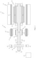
- FIG. 1 is a schematic view of a generator system, according to one or more embodiments shown and described herein;
- FIG. 2 is a side view of a main rotor for use in the generator system of FIG. 1 , according to one or more embodiments shown and described herein;
- FIG. 3 is a section view of the main rotor along line 3 - 3 of FIG. 2 , according to one or more embodiments shown and described herein;
- FIG. 4 is a section view of the main rotor along line 4 - 4 of FIG. 2 , according to one or more embodiments shown and described herein;
- FIG. 5 illustrates a layer of a rotor core of the main rotor of FIG. 2 , according to one or more embodiments shown and described herein;
- FIG. 6 A illustrates another embodiment of a main rotor having a dry configuration, according to one or more embodiments shown and described herein;
- FIG. 6 B illustrates another embodiment of a main rotor having a wet configuration, according to one or more embodiments shown and described herein;
- FIG. 7 illustrates a method of manufacturing a main rotor, according to one or more embodiments shown and described herein.
- One embodiment of a generator system includes a main machine including a main stator and a main rotor located in a cavity of the main stator.
- the rotor includes a shaft that includes closed outlets that are connected to liquid coolant conduits that deliver liquid coolant therethrough in a closed fashion and open outlets that eject liquid coolant directly into the cavity of the main stator in an open fashion.
- the generator systems described herein may be additively manufactured, such as through a three-dimensional printing process. These additive manufacturing processes can allow the generator systems or components thereof to be formed integrally as a single, monolithic component or as any number of monolithically formed subcomponents. In some embodiments, the components may all be formed from a same material, such as cobalt iron or silicon iron. Additional details of additive manufacturing processes are described in greater detail below.
- Ranges can be expressed herein as from “about” one particular value, and/or to “about” another particular value. When such a range is expressed, another embodiment includes from the one particular value and/or to the other particular value. Similarly, when values are expressed as approximations, by use of the antecedent “about,” it will be understood that the particular value forms another embodiment. It will be further understood that the endpoints of each of the ranges are significant both in relation to the other endpoint, and independently of the other endpoint.
- the generator system includes a main stator and a main rotor located in a cavity of the main stator.
- the rotor includes a shaft that includes closed outlets that are connected to liquid coolant conduits that deliver liquid coolant therethrough in a closed fashion and open outlets that eject liquid coolant directly into the cavity of the main stator in an open fashion.
- the generator system may be formed using an additive manufacturing process, where components of the generator system are formed as one or more single, monolithic parts.
- a generator system 10 is a combination of three electric machines, including a main machine 12 , an exciter 14 and a permanent magnet generator (PMG) 16 .
- the main machine 12 includes a main stator 18 and a main rotor 20 located within a cavity 25 of the main stator 18 .
- the main stator 18 connects to an inverter/converter/controller (ICC) and includes a stator core 22 and a plurality of windings 24 that are wound about pole bodies forming stator poles.
- the main rotor 20 also includes a plurality of rotor windings 26 that are wound about pole bodies forming rotor poles.
- the PMG rotor 46 may include rotor poles that are formed by permanent magnets 44 .
- the plurality of rotor poles of the main machine 12 , exciter 14 and PMG 16 can generate a plurality of magnetic fields relative to the stator poles, such that the generator system 10 can operate through the interaction of magnetic fields and current-carrying conductors to generate force or electric power.
- the exciter 14 can provide direct current to the main machine 12 and the main machine 12 and PMG 16 can supply AC electrical power when the PMG rotor 46 rotates.
- the components of the generator system 10 can be a combination of generators.
- the main machine 12 can be either a synchronous or asynchronous generator.
- there can be other accessories driven from a same rotor shaft 40 such as a liquid coolant pump, a fluid compressor, or a hydraulic pump.
- the generator system 10 can be oil cooled and thus can include a cooling system 52 .
- the cooling oil can be used to dissipate heat generated by the electrical and mechanical functions of the generator system 10 .
- the cooling system 52 can also provide for lubrication of the generator system 10 using oil.
- the generator system 10 can be configured such that the generator system 10 can operate as both a wet cavity generator and a dry cavity generator simultaneously.
- the cooling system 52 can include, for example, a cooling fluid reservoir 60 and various cooling passages.
- the rotor shaft 40 can provide one or more flow channels or paths, including a first flow channel 62 fluidly coupling the rotor shaft 40 with a plurality of closed outlets 64 , 68 .
- the rotor shaft 40 may also include a second flow channel 66 fluidly coupling the rotor shaft 40 with the plurality of closed outlets 64 , 68 . While the flow channels 62 and 66 are illustrated as connected, they may not be. Further the flow channels 62 , 66 are merely for illustration and there may be multiple flow channels 62 , 66 .
- the first plurality of closed outlets 64 and the second plurality of closed outlets 68 may be axially spaced (e.g. along the longitudinal axis of the rotor shaft 40 ) and are arranged or disposed on an outward-facing circumferential face of the rotor shaft 40 .
- the first flow channel 62 , the flow channel 66 , or a combination thereof can enable the flow of cooling fluid, such as oil, for the main rotor 20 .
- the rotor shaft 40 can also provide a first plurality of open outlets 70 and a second plurality of open outlets 72 in fluid communication with the first and second flow channels 62 and 66 or others of the flow channels.
- the first plurality of open outlets 70 and the second plurality of open outlets 72 may be axially spaced (e.g. along the longitudinal axis of the rotor shaft 40 ) and arranged or disposed on an outward-facing circumferential face of the rotor shaft 40 .
- the first plurality of open outlets 70 and the second plurality of open outlets 72 are open in that they allow liquid coolant to be sprayed directly into cavity 25 .
- the main rotor 20 is illustrated in isolation and includes the rotor shaft 40 and a rotor core 80 .
- the rotor windings 26 extend axially along the rotor core 80 .
- the plurality of rotor windings 26 are illustrated schematically in FIG. 4 .
- Multiple sets of rotor windings may be provided in each rotor core slot 82 , such as two sets of rotor windings can be stacked within a rotor core slot 82 .
- a layer of insulating material may be used to electrically isolate the layers of windings.
- a plurality of liquid coolant conduits 84 extend axially through the rotor core 80 .
- the liquid coolant conduits 84 include a first end 88 that is connected to the first plurality of closed outlets 64 and a second end 90 that is connected to the second plurality of closed outlets 68 thereby defining a closed coolant fluid passage from the first plurality of closed outlets 64 to the second plurality of closed outlets 68 .
- Each liquid coolant conduit 84 has a first radial portion 92 that extends radially outward from the rotor shaft 40 and about a disk-like hub 96 that radially supports the liquid coolant conduit 84 .
- the first radial portion 92 further extends radially outward away from the rotor shaft 40 to place an axial portion 94 proximate the rotor windings 26 .
- the axial portion 94 extends axially along a length of the rotor windings 26 ( FIG. 4 ) to a second radial portion 98 .
- the second radial portion 98 extends radially toward the rotor shaft 40 and then about another hub 96 that radially supports the liquid coolant conduit 84 .
- the second radial portion 98 then extends to the rotor shaft 40 and is fluidly connected to the second plurality of closed outlets 68 .
- the liquid coolant conduits 84 can be in fluid communication with the first plurality of closed outlets 64 and the second plurality of closed outlets 68 to provide the coolant flow path where liquid coolant flows through the rotor shaft 40 , through the first flow channel 62 ( FIG. 1 ), through the first plurality of closed outlets 64 , into the liquid coolant conduits 84 , by the rotor windings 26 and through the second plurality of closed outlets 68 .
- the liquid coolant may then return through the second flow channel 66 to be recycled or removed from the coolant flow (e.g., into a reservoir) or removed from the generator system 10 .
- the liquid coolant conduits 84 may be formed in each layer of the rotor core 80 (represented by dashed lines).
- a layer 110 of the rotor core 80 is illustrated by FIG. 5 .
- the layer 110 may be formed to include a core body 112 that includes a plurality of rotor poles 114 that extend radially outward from a central portion 116 .
- the rotor poles 114 include the pole bodies 118 that extend radially outward from the central portion 116 to respective pole shoes 120 .
- the pole shoes 120 have an enlarged dimension in a circumferential direction compared to the pole bodies 118 and overhang the windings when wound about the pole bodies 118 .
- the liquid coolant conduits 84 may be formed of a same material (e.g., an iron-cobalt-vanadium soft magnetic alloy) as the core body 112 .
- the liquid coolant conduits 84 may have any suitable cross-sectional shape, such as round and oblong. Further, the liquid coolant conduits 84 may be positioned alongside rotor slots 82 located between the pole bodies 118 . In some embodiments, a wall 124 of the liquid coolant conduits 84 may form a portion of a wall 126 of the rotor slots 122 to facilitate removal of heat from the windings when they are provided in the rotor slots 122 .
- the rotor shaft 40 further includes the first plurality of open outlets 70 and the second plurality of open outlets 72 .
- the first plurality of open outlets 70 are spaced axially from the first set of closed outlets 64 and the second plurality of open outlets 72 are spaced axially from the second plurality of closed outlets 68 .
- one or both of the first and second plurality of open outlets 70 and 72 may be aligned circumferentially with the respective first and second closed outlets 64 and 68 .
- the liquid coolant flows through the rotor shaft 40 , through the first plurality of flow channels 62 , through the first plurality of open outlets 70 , through the second plurality of open outlets 72 and directly into the cavity 25 ( FIG. 1 ). Any additional liquid coolant can return through the second plurality of flow channels 66 to be recycled or removed from the coolant flow (e.g., into a reservoir) or removed from the generator system 10 .
- the rotor shaft 40 may also include a third plurality of closed outlets 100 and a fourth plurality of closed outlets 102 in fluid communication with the first and second sets of flow channels 62 and 66 .
- the third plurality of closed outlets 100 and the fourth plurality of closed outlets 102 may be axially spaced (e.g. along the longitudinal axis of the rotor shaft 40 ) and arranged or disposed on an outward-facing circumferential face of the rotor shaft 40 .
- the third plurality of closed outlets 100 are spaced axially from the first set of closed outlets 64 and the fourth plurality of closed outlets 102 are spaced axially from the second plurality of closed outlets 68 .
- one or both of the third and fourth pluralities of closed outlets 100 and 102 may be aligned circumferentially with the respective first and second closed outlets 64 and 68 .
- a second plurality of liquid coolant conduits 104 are fluidly connected at their ends 105 to the third plurality of closed outlets 100 and a third plurality of liquid coolant conduits 106 are fluidly connected at their ends 108 to the fourth plurality of closed outlets 102 .
- a plurality of axially extending liquid conduits 130 span between the liquid coolant conduits 104 and liquid conduits 106 providing multiple, radially-spaced axially extending liquid conduits. Referring again to FIG. 5 , as with the liquid coolant conduits 84 , the axially extending liquid conduits 130 may be formed in each layer of the rotor core 80 .
- the above-described main rotor 20 including the open outlets 70 and 72 , closed outlets 64 , 68 , 100 and 102 and liquid coolant conduits 84 , 104 and 130 may be formed using an additive manufacturing process.
- Additive manufacturing processes fabricate three-dimensional structures using three-dimensional (3D) information, such as a three-dimensional computer model, of the component (e.g., the main rotor 20 or parts thereof).
- three-dimensional structures refer generally to intended or actually fabricated three-dimensional configurations (e.g., of structural material or materials) that are intended to be used for a particular purpose. Such structures may be, for example, designed with the aid of a computer aided design (CAD) program.
- CAD computer aided design
- two-dimensional structures refer generally to layers of the three-dimensional structure that when built, one over the other, form the three-dimensional structures. While referred to as “two-dimensional structures,” it should be understood that each layer includes an accompanying thickness in a third dimension, albeit the structures have a relatively planar configuration compared to a fused stack of the two-dimensional structures that form the three-dimensional structures.
- the term “electron beam” refers to any charged particle beam.
- the sources of a charged particle beam can include an electron gun, a linear actuator, etc.
- Various embodiments of the additive manufacturing apparatuses relate to methods for producing three-dimensional objects by layering two-dimensional structures one on the other by powder additive manufacturing, such as using electron beam melting (EBM), selective laser sintering (SLS) and/or selective laser melting (SLM).
- EBM electron beam melting
- SLS selective laser sintering
- SLM selective laser melting
- the use of additive manufacturing processes can allow the main rotor 20 or parts thereof to be formed as a single, monolithic piece of a same material, such as cobalt iron or silicon iron.
- FIG. 6 A another embodiment of a main rotor 140 includes many of the components described above such as liquid coolant conduits 144 , 146 , 147 and 148 and closed outlets 150 , 152 , 154 and 156 .
- the open outlets 70 and 72 of FIG. 3 are not present.
- the open outlets 70 and 72 are not printed during the additive manufacturing process effectively capping the open outlets 70 and 72 .
- the liquid coolant conduits 144 , 146 , 147 and 148 may be printed, but the closed outlets 150 , 152 , 154 and 156 may not be printed effectively capping the closed outlets 150 , 152 , 154 and 156 and connecting the liquid coolant conduits 144 , 146 , 147 and 148 to closed areas (absence of illustrated outlets 150 , 152 , 154 ) of the rotor shaft.
- the open outlets 160 and 162 may be printed, thus rendering the main rotor 140 a wet cavity machine.
- a method 200 of printing a main rotor includes selecting a three-dimensional computer model of a desired embodiment of the main rotor at step 202 .
- the three-dimensional design model may be generated using a computer aided design (CAD) program or three-dimensional scanning a prototype of the main rotor at one or more earlier steps.
- CAD computer aided design
- the rotor shaft or at least a portion thereof may be printed. Locations of the rotor shaft may remain unprinted to provide one or both of the closed and open outlets at step 206 .
- the open or closed outlets may not be printed and may be capped or printed over, referred to as closed areas of the rotor core, depending on the three-dimensional design model selected in the 202 .
- the rotor core may be printed.
- the rotor core may be printed as a solid core such that the rotor core is a single, monolithic piece. Locations of the rotor core may remain unprinted to provide the liquid coolant conduits at step 210 . Because the rotor core and liquid coolant conduits may be formed with the rotor tube, the liquid coolant conduits that are connected to the closed outlets may be formed integrally with the closed outlets and define a perimeter of the closed outlets. In some embodiments where the closed outlets are printed over, the liquid coolant conduits are connected to closed areas of the rotor core.
- the above-described generator systems include a main rotor having an interchangeable configuration, for example, between a combination of a wet and dry cavity configuration, a dry cavity configuration and a wet cavity configuration based on selection of a three-dimensional design model that is used in an additive manufacturing process. If a combination wet and dry configuration is desired, the liquid coolant conduits are printed along with the closed outlets and the open outlets in the rotor tube. If a dry cavity configuration is desired, the liquid coolant conduits are printed along with the closed outlets in the rotor tube and the open outlets are not printed. If a wet cavity configuration is desired, the liquid coolant conduits may still be printed but the closed outlets in the rotor tube are not printed.
- liquid coolant conduits may not be printed in the wet configuration.
- the interchangeable main rotors may be used with starter/generators can be used with both shared oil or self-contained oil configurations of accessory gear box (AGB) and aircraft mounted accessory drives (AMAD).
- AGB accessory gear box
- AAD aircraft mounted accessory drives
Landscapes
- Engineering & Computer Science (AREA)
- Power Engineering (AREA)
- Manufacturing & Machinery (AREA)
- Chemical & Material Sciences (AREA)
- Materials Engineering (AREA)
- Aviation & Aerospace Engineering (AREA)
- Motor Or Generator Cooling System (AREA)
Abstract
Description
-
- 1. A method for manufacturing a main rotor for a generator, the method comprising:
- printing at least part of a rotor shaft by a three-dimensional printing process, wherein the step of printing at least part of the rotor shaft comprises printing a plurality of closed outlets and a plurality of open outlets; and printing a rotor core by the three-dimensional printing process, wherein the step of printing the rotor core comprises printing a plurality of liquid coolant conduits that extend through the rotor core and fluidly connecting the plurality of liquid coolant conduits to the plurality of closed openings.
- 2. The method of any preceding clause, wherein the rotor core comprises a central portion and a plurality of rotor poles that extend radially outward from the central portion.
- 3. The method of any preceding clause, wherein the plurality of liquid coolant conduits are printed in successive layers of the rotor core within the plurality of rotor poles.
- 4. The method of any preceding clause, wherein the plurality of rotor poles each comprise a pole body that extends radially outward from the central portion and a pole shoe at an end of the pole body, wherein the plurality of liquid conduits is a first plurality of liquid coolant conduits, the rotor core comprising a second plurality of liquid coolant conduits printed in the successive layers within each pole body.
- 5. The method of any preceding clause, wherein the open outlets are printed on the rotor tube at a location outside of the rotor core.
- 6. The method of any preceding clause further comprising selecting one of a combination wet and dry cavity configuration three-dimensional computer model, a wet cavity configuration three-dimensional computer model or a dry cavity configuration three-dimensional computer model.
- 7. The method of any preceding clause comprising: selecting a dry cavity configuration three-dimensional computer model; printing at least part of another rotor shaft by a three-dimensional printing process, wherein the step of printing at least part of the another rotor shaft comprises printing another plurality of closed outlets without printing at least some open outlets; and printing another rotor core by the three-dimensional printing process, wherein the step of printing the another rotor core comprises printing another plurality of liquid coolant conduits that extend through the another rotor core and fluidly connecting the another plurality of liquid coolant conduits to the another plurality of closed openings.
- 8. The method of any preceding clause comprising: selecting a dry cavity configuration three-dimensional computer model; printing at least part of another rotor shaft by a three-dimensional printing process, wherein the step of printing at least part of the another rotor shaft comprises printing another plurality of open outlets without printing at least some closed outlets; and printing another rotor core by the three-dimensional printing process, wherein the step of printing the another rotor core comprises printing another plurality of liquid coolant conduits that extend through the another rotor core and connect to a closed area of the rotor shaft.
- 9. A main rotor for a generator system, the main rotor comprising: a rotor shaft comprising a plurality of open outlets printed on the outward-facing circumferential face of the rotor shaft; and a rotor core that extends about the rotor shaft, the rotor core comprising a plurality of liquid coolant conduits printed within the rotor core and connected to a closed area of the rotor shaft.
- 10. The main rotor of any preceding clause, wherein the rotor core comprises a central portion and a plurality of rotor poles that extend radially outward from the central portion.
- 11. The main rotor of any preceding clause, wherein the plurality of liquid coolant conduits are printed in successive layers of the rotor core within the plurality of rotor poles.
- 12. The main rotor of any preceding clause, wherein the plurality of rotor poles each comprise a pole body that extends radially outward from the central portion and a pole shoe at an end of the pole body, wherein the plurality of liquid conduits is a first plurality of liquid coolant conduits, the rotor core comprising a second plurality of liquid coolant conduits printed in the successive layers within each pole body.
- 13. The main rotor of any preceding clause further comprising a plurality of windings that are wound about each pole body.
- 14. The main rotor of any preceding clause, wherein the open outlets are printed on the rotor tube at a location outside of the rotor core.
- 15. The main rotor of any preceding clause, wherein a flow channel is printed within the rotor shaft that is in fluid communication with at least one of the plurality of closed outlets.
- 16. A generator system comprising: a main stator; and a main rotor located within a cavity of the main stator, the main rotor comprising: a rotor shaft comprising a plurality of open outlets printed on the outward-facing circumferential face of the rotor shaft; and a rotor core that extends about the rotor shaft, the rotor core comprising a plurality of liquid coolant conduits printed within the rotor core and connected to a closed area of the rotor shaft.
- 17. The generator system of any preceding clause, wherein the rotor core comprises a central portion and a plurality of rotor poles that extend radially outward from the central portion.
- 18. The generator system of any preceding clause, wherein the plurality of liquid coolant conduits are printed in successive layers of the rotor core within the plurality of rotor poles.
- 19. The generator system of any preceding clause, wherein the plurality of rotor poles each comprise a pole body that extends radially outward from the central portion and a pole shoe at an end of the pole body, wherein the plurality of liquid conduits is a first plurality of liquid coolant conduits, the rotor core comprising a second plurality of liquid coolant conduits printed in the successive layers within each pole body.
- 20. The generator system of any preceding clause, wherein the open outlets are printed on the rotor tube at a location outside of the rotor core.
Claims (17)
Priority Applications (1)
| Application Number | Priority Date | Filing Date | Title |
|---|---|---|---|
| US17/961,113 US12301063B2 (en) | 2019-12-18 | 2022-10-06 | Wet and dry cavity generator systems and methods of manufacturing the same |
Applications Claiming Priority (2)
| Application Number | Priority Date | Filing Date | Title |
|---|---|---|---|
| US16/718,360 US11489386B2 (en) | 2019-12-18 | 2019-12-18 | Wet and dry cavity generator systems and methods of manufacturing the same |
| US17/961,113 US12301063B2 (en) | 2019-12-18 | 2022-10-06 | Wet and dry cavity generator systems and methods of manufacturing the same |
Related Parent Applications (1)
| Application Number | Title | Priority Date | Filing Date |
|---|---|---|---|
| US16/718,360 Division US11489386B2 (en) | 2019-12-18 | 2019-12-18 | Wet and dry cavity generator systems and methods of manufacturing the same |
Publications (2)
| Publication Number | Publication Date |
|---|---|
| US20230043602A1 US20230043602A1 (en) | 2023-02-09 |
| US12301063B2 true US12301063B2 (en) | 2025-05-13 |
Family
ID=73642752
Family Applications (2)
| Application Number | Title | Priority Date | Filing Date |
|---|---|---|---|
| US16/718,360 Active 2040-10-11 US11489386B2 (en) | 2019-12-18 | 2019-12-18 | Wet and dry cavity generator systems and methods of manufacturing the same |
| US17/961,113 Active US12301063B2 (en) | 2019-12-18 | 2022-10-06 | Wet and dry cavity generator systems and methods of manufacturing the same |
Family Applications Before (1)
| Application Number | Title | Priority Date | Filing Date |
|---|---|---|---|
| US16/718,360 Active 2040-10-11 US11489386B2 (en) | 2019-12-18 | 2019-12-18 | Wet and dry cavity generator systems and methods of manufacturing the same |
Country Status (3)
| Country | Link |
|---|---|
| US (2) | US11489386B2 (en) |
| EP (1) | EP3840197A1 (en) |
| CN (1) | CN113078779A (en) |
Families Citing this family (4)
| Publication number | Priority date | Publication date | Assignee | Title |
|---|---|---|---|---|
| DE102021129618A1 (en) | 2021-11-12 | 2023-05-17 | MTU Aero Engines AG | Rotor shaft for an electric motor, arrangement for a rotor shaft and method for manufacturing an arrangement for a rotor shaft |
| DE102022117949A1 (en) | 2022-07-19 | 2024-01-25 | MTU Aero Engines AG | Housing flange for an electric motor housing of an electric motor, an arrangement comprising a housing flange and stator teeth and method for producing a housing flange |
| US12170474B2 (en) * | 2022-08-15 | 2024-12-17 | Rolls-Royce Corporation | Electric machine having rotor hub with shaped passages for cooling |
| DE102023207892A1 (en) * | 2023-08-17 | 2025-02-20 | Robert Bosch Gesellschaft mit beschränkter Haftung | rotor of an electrically excited synchronous machine |
Citations (26)
| Publication number | Priority date | Publication date | Assignee | Title |
|---|---|---|---|---|
| US4190780A (en) | 1976-12-30 | 1980-02-26 | Canadian General Electric Company Limited | Liquid cooled disc machines |
| US5358379A (en) | 1993-10-27 | 1994-10-25 | Westinghouse Electric Corporation | Gas turbine vane |
| US6091168A (en) * | 1998-12-22 | 2000-07-18 | Hamilton Sundstrand Corporation | Rotor for a dynamoelectric machine |
| US20030030333A1 (en) * | 2001-08-08 | 2003-02-13 | Johnsen Tyrone A. | Cooling of a rotor for a rotary electric machine |
| CN101010516A (en) | 2004-09-02 | 2007-08-01 | 英国氧气集团有限公司 | Cooling of pump rotors |
| JP2008219960A (en) | 2007-02-28 | 2008-09-18 | Toyota Central R&D Labs Inc | Rotating electric machine |
| CN102577033A (en) | 2009-04-20 | 2012-07-11 | 通用电气公司 | Integrated brushless starter/generator system |
| JP2012165620A (en) * | 2011-02-09 | 2012-08-30 | Ihi Corp | Rotating machine |
| US20160149451A1 (en) | 2014-11-24 | 2016-05-26 | Ge Aviation Systems Llc | Rotor assembly for an electric machine |
| US20160190878A1 (en) | 2014-12-31 | 2016-06-30 | Ingersoll-Rand Company | Electrical machine and method of manufacture |
| US20160204663A1 (en) | 2013-09-06 | 2016-07-14 | Ge Aviation Systems Llc | Rotor assembly for an electric machine |
| US20170063183A1 (en) | 2015-08-29 | 2017-03-02 | Abb Technology Ag | Electrical machines and fabrication methods therefor |
| CN104143884B (en) | 2013-05-07 | 2017-04-12 | F·波尔希名誉工学博士公司 | Electric machine having cooled rotor shaft |
| US9837868B2 (en) | 2014-02-28 | 2017-12-05 | Ge Aviation Systems Llc | Rotor assembly for an electric machine |
| US20180026504A1 (en) | 2016-07-20 | 2018-01-25 | Ge Aviation Systems, Llc | Method and assembly of a generator |
| US20180112531A1 (en) | 2016-10-25 | 2018-04-26 | Pratt & Whitney Canada Corp. | Rotor disc with passages |
| CN108092432A (en) | 2016-11-21 | 2018-05-29 | 奥迪股份公司 | Motor |
| US9985500B2 (en) * | 2014-03-27 | 2018-05-29 | Prippell Technologies, Llc | Induction motor with transverse liquid cooled rotor and stator |
| US20180200823A1 (en) * | 2017-01-13 | 2018-07-19 | Ge Aviation Systems Llc | Methods for manufacturing a rotor assembly for an electrical machine |
| CN108306457A (en) | 2017-01-13 | 2018-07-20 | 通用电气航空系统有限责任公司 | For method manufacturing of electric machines |
| US20180233977A1 (en) * | 2015-08-12 | 2018-08-16 | Siemens Aktiengesellschaft | Rotor Of An Electric Machine |
| US20180278127A1 (en) * | 2017-03-24 | 2018-09-27 | Ge Aviation Systems, Llc | Method and assembly of an electric machine |
| US20190074739A1 (en) | 2017-09-05 | 2019-03-07 | Rolls-Royce Plc | Electrical machine rotor |
| CN109599972A (en) | 2017-10-02 | 2019-04-09 | 通用电气航空系统有限责任公司 | Method for the rotor assembly of motor and for cooling down rotor assembly |
| US20190222079A1 (en) | 2018-01-18 | 2019-07-18 | Ge Aviation Systems, Llc | Method and apparatus for cooling an rotor assembly |
| EP3567706A1 (en) | 2018-05-10 | 2019-11-13 | Ge Aviation Systems Llc, Inc. | Assemblies made by additive manufacturing for electrical machines |
-
2019
- 2019-12-18 US US16/718,360 patent/US11489386B2/en active Active
-
2020
- 2020-11-27 EP EP20210461.8A patent/EP3840197A1/en not_active Ceased
- 2020-12-18 CN CN202011514272.5A patent/CN113078779A/en active Pending
-
2022
- 2022-10-06 US US17/961,113 patent/US12301063B2/en active Active
Patent Citations (32)
| Publication number | Priority date | Publication date | Assignee | Title |
|---|---|---|---|---|
| US4190780A (en) | 1976-12-30 | 1980-02-26 | Canadian General Electric Company Limited | Liquid cooled disc machines |
| US5358379A (en) | 1993-10-27 | 1994-10-25 | Westinghouse Electric Corporation | Gas turbine vane |
| US6091168A (en) * | 1998-12-22 | 2000-07-18 | Hamilton Sundstrand Corporation | Rotor for a dynamoelectric machine |
| US20030030333A1 (en) * | 2001-08-08 | 2003-02-13 | Johnsen Tyrone A. | Cooling of a rotor for a rotary electric machine |
| CN101010516A (en) | 2004-09-02 | 2007-08-01 | 英国氧气集团有限公司 | Cooling of pump rotors |
| JP2008219960A (en) | 2007-02-28 | 2008-09-18 | Toyota Central R&D Labs Inc | Rotating electric machine |
| US8450888B2 (en) | 2009-04-20 | 2013-05-28 | General Electric Company | Integrated brushless starter/generator system |
| CN102577033A (en) | 2009-04-20 | 2012-07-11 | 通用电气公司 | Integrated brushless starter/generator system |
| JP2012165620A (en) * | 2011-02-09 | 2012-08-30 | Ihi Corp | Rotating machine |
| CN104143884B (en) | 2013-05-07 | 2017-04-12 | F·波尔希名誉工学博士公司 | Electric machine having cooled rotor shaft |
| US20160204663A1 (en) | 2013-09-06 | 2016-07-14 | Ge Aviation Systems Llc | Rotor assembly for an electric machine |
| US10523079B2 (en) * | 2013-09-06 | 2019-12-31 | Ge Aviation Systems Llc | Rotor assembly for an electric machine with thermal management features |
| US9837868B2 (en) | 2014-02-28 | 2017-12-05 | Ge Aviation Systems Llc | Rotor assembly for an electric machine |
| US9985500B2 (en) * | 2014-03-27 | 2018-05-29 | Prippell Technologies, Llc | Induction motor with transverse liquid cooled rotor and stator |
| US20160149451A1 (en) | 2014-11-24 | 2016-05-26 | Ge Aviation Systems Llc | Rotor assembly for an electric machine |
| US20160190878A1 (en) | 2014-12-31 | 2016-06-30 | Ingersoll-Rand Company | Electrical machine and method of manufacture |
| US20180233977A1 (en) * | 2015-08-12 | 2018-08-16 | Siemens Aktiengesellschaft | Rotor Of An Electric Machine |
| US20170063183A1 (en) | 2015-08-29 | 2017-03-02 | Abb Technology Ag | Electrical machines and fabrication methods therefor |
| CN107645221A (en) | 2016-07-20 | 2018-01-30 | 通用电气航空系统有限责任公司 | The method of generator and assembling |
| US20180026504A1 (en) | 2016-07-20 | 2018-01-25 | Ge Aviation Systems, Llc | Method and assembly of a generator |
| US20180112531A1 (en) | 2016-10-25 | 2018-04-26 | Pratt & Whitney Canada Corp. | Rotor disc with passages |
| CN108092432A (en) | 2016-11-21 | 2018-05-29 | 奥迪股份公司 | Motor |
| US10476358B2 (en) | 2017-01-13 | 2019-11-12 | General Electric Company | Methods for manufacturing an electric machine |
| US20180200823A1 (en) * | 2017-01-13 | 2018-07-19 | Ge Aviation Systems Llc | Methods for manufacturing a rotor assembly for an electrical machine |
| CN108306457A (en) | 2017-01-13 | 2018-07-20 | 通用电气航空系统有限责任公司 | For method manufacturing of electric machines |
| US20180278127A1 (en) * | 2017-03-24 | 2018-09-27 | Ge Aviation Systems, Llc | Method and assembly of an electric machine |
| US20190074739A1 (en) | 2017-09-05 | 2019-03-07 | Rolls-Royce Plc | Electrical machine rotor |
| CN109599972A (en) | 2017-10-02 | 2019-04-09 | 通用电气航空系统有限责任公司 | Method for the rotor assembly of motor and for cooling down rotor assembly |
| US10756598B2 (en) | 2017-10-02 | 2020-08-25 | Ge Aviation Systems Llc | Method and apparatus for cooling a rotor assembly |
| US20190222079A1 (en) | 2018-01-18 | 2019-07-18 | Ge Aviation Systems, Llc | Method and apparatus for cooling an rotor assembly |
| EP3567706A1 (en) | 2018-05-10 | 2019-11-13 | Ge Aviation Systems Llc, Inc. | Assemblies made by additive manufacturing for electrical machines |
| CN110474498A (en) | 2018-05-10 | 2019-11-19 | 通用电气航空系统有限责任公司 | The component of the increasing material manufacturing of motor |
Non-Patent Citations (1)
| Title |
|---|
| JP-2012165620-A machine translation Mar. 21, 2024. * |
Also Published As
| Publication number | Publication date |
|---|---|
| CN113078779A (en) | 2021-07-06 |
| US20210194305A1 (en) | 2021-06-24 |
| US20230043602A1 (en) | 2023-02-09 |
| EP3840197A1 (en) | 2021-06-23 |
| US11489386B2 (en) | 2022-11-01 |
Similar Documents
| Publication | Publication Date | Title |
|---|---|---|
| US12301063B2 (en) | Wet and dry cavity generator systems and methods of manufacturing the same | |
| US10700561B2 (en) | Double-rotor flux-switching machine | |
| US7208854B1 (en) | Rotor cooling system for synchronous machines with conductive sleeve | |
| CN105978188B (en) | Electrical machine and method of manufacture | |
| US8247933B2 (en) | Methods and apparatus for a permanent magnet machine with a direct liquid cooled stator | |
| CN112787444B (en) | Electric machine with rotor cooling based on forced convection | |
| CN112787433B (en) | Electric machine with in-slot stator cooling | |
| US7640648B1 (en) | Method of fabricating a magnetic flux channel for a transverse wound motor | |
| CN118696481A (en) | Rotor for an electric machine with cooling ducts in a pole separator | |
| CN116231917A (en) | Rotor for an electric machine with radial cooling ducts in a laminated core | |
| CN110663158B (en) | Dual magnetic phase material ring for AC motor | |
| CN101262159A (en) | Transverse flux switched reluctance motor, motor for providing rotary drive and its operation method | |
| EP3280035B1 (en) | Motor-generator with radial-flux double-sided stator | |
| CN107925289A (en) | Stator coils, stators with stator coils, and rotating electrical machines with stators | |
| CN109075637A (en) | Rotating electric machine | |
| EP3599704B1 (en) | Stator assembly | |
| CN106575890A (en) | Stator for rotary electric machine and rotary electric machine equipped with same | |
| EP3944474A1 (en) | Apparatus and method and for cooling an electrical machine | |
| US20250300540A1 (en) | Torque dense electric motor | |
| US20240120781A1 (en) | Stator cooling | |
| US20230336060A1 (en) | Electric machine rotor and method of forming | |
| Khowja et al. | Trade-off study of a high power density starter-generator for turboprop aircraft system | |
| US11542029B2 (en) | Methods of forming a dual-structured aircraft engine starter/generator apparatuses | |
| EP4518106A1 (en) | Switched reluctance electric machine | |
| Tom et al. | Analysis of Integration Options for A Two-Stage Synchronous Generator |
Legal Events
| Date | Code | Title | Description |
|---|---|---|---|
| AS | Assignment |
Owner name: GE AVIATION SYSTEMS LLC, MICHIGAN Free format text: ASSIGNMENT OF ASSIGNORS INTEREST;ASSIGNORS:HUANG, HAO;MAHLE, JAMES;JIA, XIAOCHUAN;REEL/FRAME:061336/0238 Effective date: 20191212 |
|
| FEPP | Fee payment procedure |
Free format text: ENTITY STATUS SET TO UNDISCOUNTED (ORIGINAL EVENT CODE: BIG.); ENTITY STATUS OF PATENT OWNER: LARGE ENTITY |
|
| STPP | Information on status: patent application and granting procedure in general |
Free format text: DOCKETED NEW CASE - READY FOR EXAMINATION |
|
| STPP | Information on status: patent application and granting procedure in general |
Free format text: RESPONSE TO NON-FINAL OFFICE ACTION ENTERED AND FORWARDED TO EXAMINER |
|
| STPP | Information on status: patent application and granting procedure in general |
Free format text: NON FINAL ACTION MAILED |
|
| STPP | Information on status: patent application and granting procedure in general |
Free format text: RESPONSE TO NON-FINAL OFFICE ACTION ENTERED AND FORWARDED TO EXAMINER |
|
| STPP | Information on status: patent application and granting procedure in general |
Free format text: FINAL REJECTION MAILED |
|
| STPP | Information on status: patent application and granting procedure in general |
Free format text: RESPONSE AFTER FINAL ACTION FORWARDED TO EXAMINER |
|
| STPP | Information on status: patent application and granting procedure in general |
Free format text: NOTICE OF ALLOWANCE MAILED -- APPLICATION RECEIVED IN OFFICE OF PUBLICATIONS |
|
| STCF | Information on status: patent grant |
Free format text: PATENTED CASE |