US12295824B2 - Method and apparatus for fixation of implantable devices adjacent a body lumen - Google Patents
Method and apparatus for fixation of implantable devices adjacent a body lumen Download PDFInfo
- Publication number
- US12295824B2 US12295824B2 US16/532,811 US201916532811A US12295824B2 US 12295824 B2 US12295824 B2 US 12295824B2 US 201916532811 A US201916532811 A US 201916532811A US 12295824 B2 US12295824 B2 US 12295824B2
- Authority
- US
- United States
- Prior art keywords
- implantable device
- expandable balloon
- urethra
- elongate conduit
- sleeve
- Prior art date
- Legal status (The legal status is an assumption and is not a legal conclusion. Google has not performed a legal analysis and makes no representation as to the accuracy of the status listed.)
- Active
Links
Images


Classifications
-
- A—HUMAN NECESSITIES
- A61—MEDICAL OR VETERINARY SCIENCE; HYGIENE
- A61F—FILTERS IMPLANTABLE INTO BLOOD VESSELS; PROSTHESES; DEVICES PROVIDING PATENCY TO, OR PREVENTING COLLAPSING OF, TUBULAR STRUCTURES OF THE BODY, e.g. STENTS; ORTHOPAEDIC, NURSING OR CONTRACEPTIVE DEVICES; FOMENTATION; TREATMENT OR PROTECTION OF EYES OR EARS; BANDAGES, DRESSINGS OR ABSORBENT PADS; FIRST-AID KITS
- A61F2/00—Filters implantable into blood vessels; Prostheses, i.e. artificial substitutes or replacements for parts of the body; Appliances for connecting them with the body; Devices providing patency to, or preventing collapsing of, tubular structures of the body, e.g. stents
- A61F2/0004—Closure means for urethra or rectum, i.e. anti-incontinence devices or support slings against pelvic prolapse
- A61F2/0022—Closure means for urethra or rectum, i.e. anti-incontinence devices or support slings against pelvic prolapse placed deep in the body opening
- A61F2/0027—Closure means for urethra or rectum, i.e. anti-incontinence devices or support slings against pelvic prolapse placed deep in the body opening inflatable
-
- A—HUMAN NECESSITIES
- A61—MEDICAL OR VETERINARY SCIENCE; HYGIENE
- A61F—FILTERS IMPLANTABLE INTO BLOOD VESSELS; PROSTHESES; DEVICES PROVIDING PATENCY TO, OR PREVENTING COLLAPSING OF, TUBULAR STRUCTURES OF THE BODY, e.g. STENTS; ORTHOPAEDIC, NURSING OR CONTRACEPTIVE DEVICES; FOMENTATION; TREATMENT OR PROTECTION OF EYES OR EARS; BANDAGES, DRESSINGS OR ABSORBENT PADS; FIRST-AID KITS
- A61F2/00—Filters implantable into blood vessels; Prostheses, i.e. artificial substitutes or replacements for parts of the body; Appliances for connecting them with the body; Devices providing patency to, or preventing collapsing of, tubular structures of the body, e.g. stents
- A61F2/0004—Closure means for urethra or rectum, i.e. anti-incontinence devices or support slings against pelvic prolapse
- A61F2/0031—Closure means for urethra or rectum, i.e. anti-incontinence devices or support slings against pelvic prolapse for constricting the lumen; Support slings for the urethra
- A61F2/0036—Closure means for urethra or rectum, i.e. anti-incontinence devices or support slings against pelvic prolapse for constricting the lumen; Support slings for the urethra implantable
- A61F2/004—Closure means for urethra or rectum, i.e. anti-incontinence devices or support slings against pelvic prolapse for constricting the lumen; Support slings for the urethra implantable inflatable
-
- A—HUMAN NECESSITIES
- A61—MEDICAL OR VETERINARY SCIENCE; HYGIENE
- A61F—FILTERS IMPLANTABLE INTO BLOOD VESSELS; PROSTHESES; DEVICES PROVIDING PATENCY TO, OR PREVENTING COLLAPSING OF, TUBULAR STRUCTURES OF THE BODY, e.g. STENTS; ORTHOPAEDIC, NURSING OR CONTRACEPTIVE DEVICES; FOMENTATION; TREATMENT OR PROTECTION OF EYES OR EARS; BANDAGES, DRESSINGS OR ABSORBENT PADS; FIRST-AID KITS
- A61F2/00—Filters implantable into blood vessels; Prostheses, i.e. artificial substitutes or replacements for parts of the body; Appliances for connecting them with the body; Devices providing patency to, or preventing collapsing of, tubular structures of the body, e.g. stents
- A61F2/0077—Special surfaces of prostheses, e.g. for improving ingrowth
-
- A—HUMAN NECESSITIES
- A61—MEDICAL OR VETERINARY SCIENCE; HYGIENE
- A61M—DEVICES FOR INTRODUCING MEDIA INTO, OR ONTO, THE BODY; DEVICES FOR TRANSDUCING BODY MEDIA OR FOR TAKING MEDIA FROM THE BODY; DEVICES FOR PRODUCING OR ENDING SLEEP OR STUPOR
- A61M25/00—Catheters; Hollow probes
- A61M25/0017—Catheters; Hollow probes specially adapted for long-term hygiene care, e.g. urethral or indwelling catheters to prevent infections
-
- A—HUMAN NECESSITIES
- A61—MEDICAL OR VETERINARY SCIENCE; HYGIENE
- A61F—FILTERS IMPLANTABLE INTO BLOOD VESSELS; PROSTHESES; DEVICES PROVIDING PATENCY TO, OR PREVENTING COLLAPSING OF, TUBULAR STRUCTURES OF THE BODY, e.g. STENTS; ORTHOPAEDIC, NURSING OR CONTRACEPTIVE DEVICES; FOMENTATION; TREATMENT OR PROTECTION OF EYES OR EARS; BANDAGES, DRESSINGS OR ABSORBENT PADS; FIRST-AID KITS
- A61F2/00—Filters implantable into blood vessels; Prostheses, i.e. artificial substitutes or replacements for parts of the body; Appliances for connecting them with the body; Devices providing patency to, or preventing collapsing of, tubular structures of the body, e.g. stents
- A61F2/0077—Special surfaces of prostheses, e.g. for improving ingrowth
- A61F2002/0086—Special surfaces of prostheses, e.g. for improving ingrowth for preferentially controlling or promoting the growth of specific types of cells or tissues
-
- A—HUMAN NECESSITIES
- A61—MEDICAL OR VETERINARY SCIENCE; HYGIENE
- A61F—FILTERS IMPLANTABLE INTO BLOOD VESSELS; PROSTHESES; DEVICES PROVIDING PATENCY TO, OR PREVENTING COLLAPSING OF, TUBULAR STRUCTURES OF THE BODY, e.g. STENTS; ORTHOPAEDIC, NURSING OR CONTRACEPTIVE DEVICES; FOMENTATION; TREATMENT OR PROTECTION OF EYES OR EARS; BANDAGES, DRESSINGS OR ABSORBENT PADS; FIRST-AID KITS
- A61F2250/00—Special features of prostheses classified in groups A61F2/00 - A61F2/26 or A61F2/82 or A61F9/00 or A61F11/00 or subgroups thereof
- A61F2250/0014—Special features of prostheses classified in groups A61F2/00 - A61F2/26 or A61F2/82 or A61F9/00 or A61F11/00 or subgroups thereof having different values of a given property or geometrical feature, e.g. mechanical property or material property, at different locations within the same prosthesis
- A61F2250/0018—Special features of prostheses classified in groups A61F2/00 - A61F2/26 or A61F2/82 or A61F9/00 or A61F11/00 or subgroups thereof having different values of a given property or geometrical feature, e.g. mechanical property or material property, at different locations within the same prosthesis differing in elasticity, stiffness or compressibility
Definitions
- the present subject matter relates to method and apparatus for fixation of implantable devices adjacent a body lumen.
- the present application relates to method and apparatus for reducing migration and rotation of implantable devices including an expandable element and an elongate portion.
- FIG. 1 A shows an example of placement of implantable devices with respect to a human bladder and urethra according to one embodiment of the present subject matter.
- FIG. 1 B demonstrates migration of one of the two implantable devices.
- FIG. 1 C demonstrates rotation of one expandable element of one of the two implantable devices.
- FIG. 2 shows placement of a sleeve adapted to provide ingrowth to provide an adhesion according to one embodiment of the present subject matter.
- FIG. 3 shows a closeup of the sleeve of FIG. 2 .
- FIG. 4 shows a cross section of an implantable device including a sleeve attached using an adhesive according to one embodiment of the present subject matter.
- FIG. 5 shows a cross section of surface structure adapted to enhance ingrowth according to one embodiment of the present subject matter.
- FIG. 6 shows a cross section of surface structure adapted to enhance ingrowth and resist migration according to one embodiment of the present subject matter.
- FIG. 7 shows a cross section of a helical sleeve structure adapted to enhance ingrowth according to one embodiment of the present subject matter.
- FIG. 8 shows one example of a tool for removal of a helical sleeve structure according to one embodiment of the present subject matter.
- FIG. 9 shows one example of an expandable tool for removal of a helical sleeve structure according to one embodiment of the present subject matter.
- FIG. 10 shows one example of a split ring device adapted to enhance ingrowth according to one embodiment of the present subject matter.
- FIG. 11 shows one example of a segmented ring device adapted to enhance ingrowth according to one embodiment of the present subject matter.
- FIG. 12 A shows one example of a hook adapted for fixation according to one embodiment of the present subject matter.
- FIG. 12 B shows a cross section of a portion of the implantable device of FIG. 12 A according to one embodiment of the present subject matter.
- FIG. 13 shows one example of a plurality of hooks adapted for fixation according to one embodiment of the present subject matter.
- FIGS. 14 A and 14 B show one example of use of ingrowth-promoting material at a distal end of an apparatus according to one embodiment of the present subject matter.
- FIGS. 15 A to 15 E show some examples of an implantable device featuring a variable stiffness design adapted to reduce rotation according to various embodiments of the present subject matter.
- FIG. 16 A shows one example of an external stiffener for an implantable device according to one embodiment of the present subject matter.
- FIGS. 16 B and 16 C show one example of an externally coiled stiffener for an implantable device according to one embodiment of the present subject matter.
- FIGS. 16 D and 16 E show different examples of an internally coiled stiffener for an implantable device according to various embodiments of the present subject matter.
- FIG. 17 shows one example of a restraint on a proximal bond according to one embodiment of the present subject matter.
- FIG. 18 A shows one embodiment of an irregular shape of an expandable element of the implantable device according to one embodiment of the present subject matter, as compared to that of FIG. 18 B .
- FIG. 19 shows one embodiment of a microtextured expandable element according to one embodiment of the present subject matter.
- FIG. 20 shows one embodiment of an extra stabilizing balloon for an implantable device according to one embodiment of the present subject matter.
- the present subject matter relates to implantable devices which can be placed near a patient's urethra to improve continence.
- the implantable devices are described in applications such as such as the implantable devices described in U.S. Pat. Nos. 6,045,498, 5,964,806, 6,579,224, and 6,419,624 and their related patents and applications, the description; of which are hereby incorporated in their entirety.
- Such applications also contain information as to the placement of the implantable devices. Placement of such devices is also discussed in U.S. Provisional Patent Application Ser. No. 61/039,738, filed Mar. 26, 2008, entitled: METHOD AND APPARATUS FOR PLACEMENT OF IMPLANTABLE DEVICE ADJACENT A BODY LUMEN, which is incorporated by reference in its entirety.
- FIG. 1 A shows an example of placement of implantable devices with respect to a human bladder and urethra according to one embodiment of the present subject matter.
- an expandable element 10 is connected to an elongate conduit 11 and terminates in a port 12 , such as a septum.
- the expandable element 10 is implanted proximal the urethra 6 near the bladder 5 .
- Such location is also referred to as the “bladder neck.”
- the actual positions of the expandable elements 10 of such devices with respect to the urethra 6 and bladder neck may vary; however, FIG. 1 A shows the original position of the devices compared to the positions in FIGS. 1 B and 1 C for purposes of demonstration of the unwanted aspects of migration and rotation.
- FIG. 1 B demonstrates migration of one of the two implantable devices.
- FIG. 1 C demonstrates rotation of one expandable element of one of the two implantable devices.
- the expandable element 10 of implantable device 20 is shown as being rotated in position relative to its original placement.
- the rotation can result in displacement of the expandable element 10 , which may reduce the efficacy of the implantation for purposes of enhancing coaptation, and continence.
- rotation can be problematic even in cases where the expandable element 10 is not substantially displaced because the elongate conduit 11 can apply unwanted force on the expandable element 10 and may result in device failure over time due to erosion of material.
- FIG. 2 shows placement of a sleeve adapted to provide ingrowth to provide an adhesion according to one embodiment of the present subject matter.
- a small adhesion forms near the end of the tubing closest to the expandable element 10 by the use of an ingrowth collar or sleeve 30 .
- Different materials can be used, including but not limited to EPTFE (expanded polytetrafluoroethelene as used in some vascular grafts) to encircle the elongate conduit 11 near the expandable element 10 .
- the ingrowth collar or sleeve 30 allows the adhesion to form which is a form of fixation of the device to avoid migration and to avoid rotation.
- Other ingrowth materials may include polypropylene or polyethylene mesh as used for hernia repairs or open cell silicone or polyurethane foams.
- the ingrowth sleeve 30 as designed to have less than a 5 lb. pull strength. Other pull strength limits are possible without departing from the scope of the present subject matter.
- the ingrowth material is bioresorbable so that it fixes the device in place after a short time allowing the surrounding tissue to adapt and stabilize the device but would be resorbed over a longer timeframe and allow the device to be easily removed if need be.
- a bioresorbable material is polylactic acid.
- the implantable device 20 can be removed by cutting off the septum, feeding a cylindrical tool over the implantable device, and using the tool to go over the conduit, cutting the adhesion to facilitate removal of the implantable device at a pull strength that is less than what would destroy the implantable device.
- the cylindrical tool may also have a slot along its length so that it can be fit over and along the conduit so that the part need not be cut off.
- the tool can cut between the elongate conduit and the sleeve or the tool can cut the sleeve away from the tissue.
- One type of tool to accomplish the cutting is the use of a properly positioned beveled blade. Other tools and approaches are possible without departing from the scope of the present subject matter.
- FIG. 4 shows a cross section of an implantable device 44 including a sleeve 40 attached to elongate conduit 11 using an adhesive 42 according to one embodiment of the present subject matter.
- Such sleeves 40 provide adequate fixation of the implantable device 44 during its implantation.
- the adhesive has a tear strength which is less than the pull strength limit of the implantable device 44 .
- the sleeve 40 may stay in place while the glue 42 shears as the implantable device 44 is pulled out of the patient.
- the split ring or segmented ring sleeves as shown in FIGS. 10 and 11 may be used to allow the withdrawal of the implantable device. This is especially useful for devices where the cross section at the expandable element 10 is greater than the cross section for the elongate conduit 11 .
- Other types of split ring sleeves may be used without departing from the scope of the present subject matter.
- FIG. 5 shows a cross section of surface structure adapted to enhance ingrowth according to one embodiment of the present subject matter.
- the surface structure can be porous and is selected to provide the proper pull strength, yet retain the implantable device in position during its normal use.
- FIG. 6 shows a cross section of surface structure adapted to enhance ingrowth and resist migration according to one embodiment of the present subject matter.
- the angled nature of the structure forms additional resistance to migrations back down the dialation path.
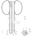
- FIG. 7 shows a cross section of a helical sleeve structure adapted to enhance ingrowth according to one embodiment of the present subject matter.
- the helical sleeve structure 70 over the elongate conduit 11 acts to fix the implantable device. To remove the device, it is screwed out of the tissue.
- a pushwire or other rod is used to withdraw the device.
- the pushwire or rod can be keyed to facilitate application of torque to withdraw the device.
- a structure, such as that shown in FIG. 8 is used to lock the pushwire or rod with a channel or other receiver in the implantable device for withdrawal.
- FIG. 8 shows one example of a tool for removal of a helical sleeve structure according to one embodiment of the present subject matter.
- a collet-type device such as the expanding device shown in FIG. 9 is used to withdraw the device.
- FIG. 9 shows one example of an expandable tool for removal of a helical sleeve structure according to one embodiment of the present subject matter.
- a remote actuator (not shown) is used to expand distal ring 90 so as to engage with a lumen or other feature of the implantable device which is to be extracted.
- FIG. 12 A shows one example of a hook adapted for fixation according to one embodiment of the present subject matter.
- a Nitinol hook 120 is threaded through an inner lumen 124 of the elongate conduit 11 of implantable device 122 and exits the inner lumen 124 from an exit on the elongate conduit 11 to serve as a fixation to the local tissue.
- the exit is proximal to the expandable element 10 of the implantable device 122 .
- Other types of hooks may be used without departing from the scope of the present subject matter.
- the hook is placed near the expandable element 10 of the implantable device 122 to retain it in position.
- inner lumen 12 B shows a cross section of elongate conduit showing a cross section of hook 120 in the space of what was the inner lumen 124 and another inner lumen 126 in communication with expandable element 10 .
- inner lumen 126 is connected to a port with a septum (not shown) as described in the various documents incorporated by reference.
- inner lumen 124 is used with various implantation tools such as a pushrod or other tool to place implantable device 122 in position.
- various inner lumens for implantable devices are described in patent documents, including, but not limited to, U.S. Pat. Nos.
- FIG. 13 shows one example of a plurality of hooks adapted for fixation according to one embodiment of the present subject matter.
- fixation hooks 130 at the distal tip of the elongate conduit 11 are deployed to provide fixation to the tissue after the implantable device 132 is placed in its desired position.
- the expandable element 10 is expanded and the hooks 130 are recessed to shield bladder from puncturing.
- Other hook positions, shapes, and numbers are possible without departing from the scope of the present subject matter.
- FIGS. 14 A and 14 B show one example of use of ingrowth-promoting material at a distal end of an implantable device according to one embodiment of the present subject matter.
- a patch or coating of ingrowth-promoting material 140 at the distal end of the device 142 provides adhesion at or near the distal end of the device 142 .
- the ingrowth material is bioresorbable so that it fixes the device in place after a short time allowing the surrounding tissue to adapt and stabilize the device but would be resorbed over a longer timeframe and allow the device to be easily removed if need be.
- a bioresorbable material is polylactic acid. It is understood that various materials, shapes and positions can be used without departing from the scope of the present subject matter.
- FIGS. 15 A-E show some examples of an implantable device featuring a variable stiffness design adapted to reduce rotation according to various embodiments of the present subject matter.
- FIG. 15 A different stiffeners are shown, which may be used individually, or in combination, in various applications.
- FIG. 15 B is a cross section drawing showing stiffener 153 which is a form of annular ring with an aperture for filling expandable element 10 .
- FIG. 15 C is a cross section showing a stiffening member 155
- FIG. 15 D shows a cross section showing a separate lumen with a stiffening member 157 .
- FIG. 15 E shows a cross section with an annular stiffening member 159 placed in inner lumen 124 .
- expansion of the expandable element 10 can also make tubing in central portion stretch and can also have a preferential force on the tubing and may cause it to rotate.
- a stiffener of varying stiffness can he inserted in a lumen of the elongate conduit to provide more stiffening at the distal end than at the proximal end of the implantable device 150 .
- a stiffener 157 is added to a third central lumen of the implantable device after it is deployed into position.
- the stiffening effect is built into the implantable device as it is manufactured.
- a stiffener 159 is placed in the same lumen 124 that is used to position the implantable device. This could be done by the surgeon after removing the pushwire at time of implant. Other types of stiffeners and deployments are possible without departing from the scope of the present subject matter.
- FIG. 16 A shows one example of an external stiffener for an implantable device according to one embodiment of the present subject matter.
- sleeve 162 provides additional stiffness at the proximal bond area of elongate conduit 11 of the expandable element 10 .
- the sleeve 162 continues into the expandable element 10 portion of the elongate conduit 11 .
- the sleeve 162 is manufactured as an integral portion of elongate conduit 11 .
- a lubricious coating, sleeve, or material can be positioned anywhere along the elongate conduit or about the external stiffener in embodiments which employ a stiffener, or both, to reduce or eliminate wear should the expandable element 10 come in contact with the stiffener and/or the elongate conduit. In such events, the lubricious coating, sleeve, or material would prevent wear of the expandable element 10 .
- FIGS. 16 B and 16 C show one example of an externally coiled stiffener for an implantable device according to one embodiment of the present subject matter.
- coil 164 can be placed outside of elongate conduit 11 .
- a coil can also be displosed within the elongate conduit 11 as shown as coil 168 in FIGS. 16 D and 16 E .
- Coils 164 and 168 provide additional stiffness to prevent rotation of the expandable element 10 of implantable device 166 .
- FIG. 17 shows one example of a restraint on a proximal bond according to one embodiment of the present subject matter.
- the restraint 172 on the proximal bond of the expandable element 10 to elongate conduit 11 reduces or eliminates wear and/or erosion on the proximal bond.
- the restraint 172 is a collar that is attached to the implantable device 170 .
- the restraint 172 is generated by one or more additional dips in the coating process that produces the implantable device 170 .
- the restraint provides asymmetric balloon inflation of the expandable element 10 . Other shapes and constraints and asymmetries are possible without departing from the scope of the present subject matter.
- Expandable elements with asymmetrical shapes can he engineered to reduce the possibility of contact with the elongate conduit by the expandable element.
- the bulge shown in the example of FIG. 17 is larger at the distal end of the expandable element, which can reduce the tendency of the expandable element to come in contact with the elongate conduit.
- FIG. 18 A shows one embodiment of an irregular shape of an expandable element of the implantable device according to one embodiment of the present subject matter, as compared to that of FIG. 18 B .
- the irregular shape is made squarer than that of FIG. 18 B to avoid rotation.
- Various different shapes may be used without departing from the scope of the present subject matter.
- FIG. 19 shows one embodiment of a microtextured expandable element according to one embodiment of the present subject matter.
- a portion of the wall of expandable element 192 is microtextured 194 to reduce rotation.
- a tool can be employed to remove the expandable element 10 .
- FIG. 20 shows one embodiment of an extra stabilizing balloon for an implantable device according to one embodiment of the present subject matter.
- Balloon 202 is placed to prevent the implantable device from migrating, and may avoid rotation by holding the elongate conduit in place and thereby limit the expandable element 10 from rotating.
Landscapes
- Health & Medical Sciences (AREA)
- Life Sciences & Earth Sciences (AREA)
- Urology & Nephrology (AREA)
- General Health & Medical Sciences (AREA)
- Public Health (AREA)
- Biomedical Technology (AREA)
- Heart & Thoracic Surgery (AREA)
- Veterinary Medicine (AREA)
- Engineering & Computer Science (AREA)
- Animal Behavior & Ethology (AREA)
- Transplantation (AREA)
- Oral & Maxillofacial Surgery (AREA)
- Vascular Medicine (AREA)
- Cardiology (AREA)
- Epidemiology (AREA)
- Biophysics (AREA)
- Pulmonology (AREA)
- Anesthesiology (AREA)
- Hematology (AREA)
- Prostheses (AREA)
Abstract
Description
Claims (19)
Priority Applications (2)
| Application Number | Priority Date | Filing Date | Title |
|---|---|---|---|
| US16/532,811 US12295824B2 (en) | 2008-05-16 | 2019-08-06 | Method and apparatus for fixation of implantable devices adjacent a body lumen |
| US19/176,983 US20250302601A1 (en) | 2008-05-16 | 2025-04-11 | Method and apparatus for fixation of implantable devices adjacent a body lumen |
Applications Claiming Priority (6)
| Application Number | Priority Date | Filing Date | Title |
|---|---|---|---|
| US5375808P | 2008-05-16 | 2008-05-16 | |
| US12/467,257 US20100292530A1 (en) | 2009-05-16 | 2009-05-16 | Method and apparatus for fixation of implantable devices adjacent a body lumen |
| US14/169,988 US20140148794A1 (en) | 2008-05-16 | 2014-01-31 | Method and apparatus for fixation of implantable devices adjacent a body lumen |
| US15/143,784 US20160242886A1 (en) | 2008-05-16 | 2016-05-02 | Method and apparatus for fixation of implantable devices adjacent a body lumen |
| US15/371,591 US20170079762A1 (en) | 2008-05-16 | 2016-12-07 | Method and apparatus for fixation of implantable devices adjacent a body lumen |
| US16/532,811 US12295824B2 (en) | 2008-05-16 | 2019-08-06 | Method and apparatus for fixation of implantable devices adjacent a body lumen |
Related Parent Applications (1)
| Application Number | Title | Priority Date | Filing Date |
|---|---|---|---|
| US15/371,591 Continuation US20170079762A1 (en) | 2008-05-16 | 2016-12-07 | Method and apparatus for fixation of implantable devices adjacent a body lumen |
Related Child Applications (1)
| Application Number | Title | Priority Date | Filing Date |
|---|---|---|---|
| US19/176,983 Continuation US20250302601A1 (en) | 2008-05-16 | 2025-04-11 | Method and apparatus for fixation of implantable devices adjacent a body lumen |
Publications (2)
| Publication Number | Publication Date |
|---|---|
| US20200022796A1 US20200022796A1 (en) | 2020-01-23 |
| US12295824B2 true US12295824B2 (en) | 2025-05-13 |
Family
ID=43069056
Family Applications (6)
| Application Number | Title | Priority Date | Filing Date |
|---|---|---|---|
| US12/467,257 Abandoned US20100292530A1 (en) | 2008-05-16 | 2009-05-16 | Method and apparatus for fixation of implantable devices adjacent a body lumen |
| US14/169,988 Abandoned US20140148794A1 (en) | 2008-05-16 | 2014-01-31 | Method and apparatus for fixation of implantable devices adjacent a body lumen |
| US15/143,784 Abandoned US20160242886A1 (en) | 2008-05-16 | 2016-05-02 | Method and apparatus for fixation of implantable devices adjacent a body lumen |
| US15/371,591 Abandoned US20170079762A1 (en) | 2008-05-16 | 2016-12-07 | Method and apparatus for fixation of implantable devices adjacent a body lumen |
| US16/532,811 Active US12295824B2 (en) | 2008-05-16 | 2019-08-06 | Method and apparatus for fixation of implantable devices adjacent a body lumen |
| US19/176,983 Pending US20250302601A1 (en) | 2008-05-16 | 2025-04-11 | Method and apparatus for fixation of implantable devices adjacent a body lumen |
Family Applications Before (4)
| Application Number | Title | Priority Date | Filing Date |
|---|---|---|---|
| US12/467,257 Abandoned US20100292530A1 (en) | 2008-05-16 | 2009-05-16 | Method and apparatus for fixation of implantable devices adjacent a body lumen |
| US14/169,988 Abandoned US20140148794A1 (en) | 2008-05-16 | 2014-01-31 | Method and apparatus for fixation of implantable devices adjacent a body lumen |
| US15/143,784 Abandoned US20160242886A1 (en) | 2008-05-16 | 2016-05-02 | Method and apparatus for fixation of implantable devices adjacent a body lumen |
| US15/371,591 Abandoned US20170079762A1 (en) | 2008-05-16 | 2016-12-07 | Method and apparatus for fixation of implantable devices adjacent a body lumen |
Family Applications After (1)
| Application Number | Title | Priority Date | Filing Date |
|---|---|---|---|
| US19/176,983 Pending US20250302601A1 (en) | 2008-05-16 | 2025-04-11 | Method and apparatus for fixation of implantable devices adjacent a body lumen |
Country Status (1)
| Country | Link |
|---|---|
| US (6) | US20100292530A1 (en) |
Families Citing this family (6)
| Publication number | Priority date | Publication date | Assignee | Title |
|---|---|---|---|---|
| US20100292530A1 (en) | 2009-05-16 | 2010-11-18 | Uromedica, Inc. | Method and apparatus for fixation of implantable devices adjacent a body lumen |
| JP2014506156A (en) * | 2010-12-23 | 2014-03-13 | エル ウント エム コンスルティンク ウント トラディンク ゲゼルシャフト ミット ベシュレンクテル ハフツング ウント コンパニー コマンディトゲゼルシャフト | Urine incontinence prevention device comprising a fixation device immovably embedded in body tissue |
| US11510766B2 (en) | 2019-02-14 | 2022-11-29 | Uromedica, Inc. | Method and apparatus for monitoring implantable device for urinary continence |
| US20210030544A1 (en) * | 2019-07-31 | 2021-02-04 | Boston Scientific Scimed, Inc. | Penile implant outer support structure within neophallus for neophallus surgery |
| US11759301B2 (en) * | 2020-06-23 | 2023-09-19 | Uromedica, Inc. | Method and apparatus for fixation of implantable device for urinary continence |
| AU2022348556B2 (en) * | 2021-09-14 | 2026-02-05 | Uromedica, Inc. | Implantable urinary continence device with helical anchor |
Citations (12)
| Publication number | Priority date | Publication date | Assignee | Title |
|---|---|---|---|---|
| US5167614A (en) * | 1991-10-29 | 1992-12-01 | Medical Engineering Corporation | Prostatic stent |
| US5964806A (en) * | 1997-06-12 | 1999-10-12 | Uromedica, Inc. | Adjustable implantable genitourinary device |
| US20030083539A1 (en) * | 2000-11-17 | 2003-05-01 | Boris Leschinsky | Intra-aortic balloon catheter for long-term implantation |
| US6579224B1 (en) * | 1999-10-11 | 2003-06-17 | Uromedica, Inc. | Apparatus and method for inserting an adjustable implantable genitourinary device |
| US20040186507A1 (en) * | 1998-09-10 | 2004-09-23 | Percardia, Inc. | Stent delivery system and method of use |
| US20040215054A1 (en) | 2003-04-24 | 2004-10-28 | Siegel Steven W. | Male urethral prosthesis |
| US20040230282A1 (en) * | 2003-04-11 | 2004-11-18 | Cates Adam W. | Acute and chronic fixation for subcutaneous electrodes |
| US7022106B2 (en) * | 2001-11-30 | 2006-04-04 | Abbott Laboratories Vascular Entities Limited | Catheter having enhanced distal pushability |
| US20060129178A1 (en) * | 1991-04-05 | 2006-06-15 | Nikolaus Reifart | Adjustably stiffenable convertible catheter assembly |
| US20070043255A1 (en) * | 2005-08-22 | 2007-02-22 | O'donnell Pat D | Surgical instrument for treating female pelvic prolapse |
| US20070270890A1 (en) * | 2006-03-16 | 2007-11-22 | Dennis Miller | System and Method for Treating Tissue Wall Prolapse |
| US20100292530A1 (en) | 2009-05-16 | 2010-11-18 | Uromedica, Inc. | Method and apparatus for fixation of implantable devices adjacent a body lumen |
-
2009
- 2009-05-16 US US12/467,257 patent/US20100292530A1/en not_active Abandoned
-
2014
- 2014-01-31 US US14/169,988 patent/US20140148794A1/en not_active Abandoned
-
2016
- 2016-05-02 US US15/143,784 patent/US20160242886A1/en not_active Abandoned
- 2016-12-07 US US15/371,591 patent/US20170079762A1/en not_active Abandoned
-
2019
- 2019-08-06 US US16/532,811 patent/US12295824B2/en active Active
-
2025
- 2025-04-11 US US19/176,983 patent/US20250302601A1/en active Pending
Patent Citations (16)
| Publication number | Priority date | Publication date | Assignee | Title |
|---|---|---|---|---|
| US20060129178A1 (en) * | 1991-04-05 | 2006-06-15 | Nikolaus Reifart | Adjustably stiffenable convertible catheter assembly |
| US5167614A (en) * | 1991-10-29 | 1992-12-01 | Medical Engineering Corporation | Prostatic stent |
| US5964806A (en) * | 1997-06-12 | 1999-10-12 | Uromedica, Inc. | Adjustable implantable genitourinary device |
| US6045498A (en) | 1997-06-12 | 2000-04-04 | Uromedica, Inc. | Method for adjustably restricting a body lumen |
| US20040186507A1 (en) * | 1998-09-10 | 2004-09-23 | Percardia, Inc. | Stent delivery system and method of use |
| US6579224B1 (en) * | 1999-10-11 | 2003-06-17 | Uromedica, Inc. | Apparatus and method for inserting an adjustable implantable genitourinary device |
| US20030083539A1 (en) * | 2000-11-17 | 2003-05-01 | Boris Leschinsky | Intra-aortic balloon catheter for long-term implantation |
| US7022106B2 (en) * | 2001-11-30 | 2006-04-04 | Abbott Laboratories Vascular Entities Limited | Catheter having enhanced distal pushability |
| US20040230282A1 (en) * | 2003-04-11 | 2004-11-18 | Cates Adam W. | Acute and chronic fixation for subcutaneous electrodes |
| US20040215054A1 (en) | 2003-04-24 | 2004-10-28 | Siegel Steven W. | Male urethral prosthesis |
| US20070043255A1 (en) * | 2005-08-22 | 2007-02-22 | O'donnell Pat D | Surgical instrument for treating female pelvic prolapse |
| US20070270890A1 (en) * | 2006-03-16 | 2007-11-22 | Dennis Miller | System and Method for Treating Tissue Wall Prolapse |
| US20140148794A1 (en) | 2008-05-16 | 2014-05-29 | Uromedica, Inc. | Method and apparatus for fixation of implantable devices adjacent a body lumen |
| US20160242886A1 (en) | 2008-05-16 | 2016-08-25 | Uromedica, Inc. | Method and apparatus for fixation of implantable devices adjacent a body lumen |
| US20170079762A1 (en) | 2008-05-16 | 2017-03-23 | Uromedica, Inc. | Method and apparatus for fixation of implantable devices adjacent a body lumen |
| US20100292530A1 (en) | 2009-05-16 | 2010-11-18 | Uromedica, Inc. | Method and apparatus for fixation of implantable devices adjacent a body lumen |
Non-Patent Citations (18)
Also Published As
| Publication number | Publication date |
|---|---|
| US20200022796A1 (en) | 2020-01-23 |
| US20250302601A1 (en) | 2025-10-02 |
| US20170079762A1 (en) | 2017-03-23 |
| US20160242886A1 (en) | 2016-08-25 |
| US20140148794A1 (en) | 2014-05-29 |
| US20100292530A1 (en) | 2010-11-18 |
Similar Documents
| Publication | Publication Date | Title |
|---|---|---|
| US20250302601A1 (en) | Method and apparatus for fixation of implantable devices adjacent a body lumen | |
| US12042372B2 (en) | Devices, systems and methods for treating benign prostatic hyperplasia and other conditions | |
| JP2660101B2 (en) | Esophageal stent and delivery device | |
| EP2694152B1 (en) | Apical puncture access and closure system | |
| EP3191027B1 (en) | Mitral repair and replacement devices | |
| EP2088965B1 (en) | Segmented ring placement | |
| EP1599246B1 (en) | Medical device delivery system | |
| US8845682B2 (en) | Vasculature closure devices and methods | |
| US20070073391A1 (en) | System and method for delivering a mitral valve repair device | |
| JP2007535335A (en) | Annulus reduction system | |
| JP6431183B2 (en) | In-vivo prosthesis delivery system with improved storage | |
| JP7182115B2 (en) | tubular medical device | |
| CA3075925C (en) | Medical system for annuloplasty | |
| US20140163608A1 (en) | Implantable sealing device | |
| US20170216068A1 (en) | Anti-migration stent deployment delivery systems and methods | |
| US20090270976A1 (en) | Stent Graft Fixation System and Method of Use | |
| US20150335431A1 (en) | Penile surgery systems and methods | |
| CA3259184A1 (en) | Urethral treatment apparatus and method | |
| JP2024511626A (en) | Apparatus and method for implant treatment of arteriovenous grafts | |
| JP2023503356A (en) | annuloplasty device | |
| CN114007549A (en) | Medical arrangement for introducing an object into an anatomical target location |
Legal Events
| Date | Code | Title | Description |
|---|---|---|---|
| AS | Assignment |
Owner name: UROMEDICA, INC., MINNESOTA Free format text: ASSIGNMENT OF ASSIGNORS INTEREST;ASSIGNORS:COOK, TIMOTHY C.;BURTON, JOHN H.;REEL/FRAME:049971/0192 Effective date: 20090526 |
|
| FEPP | Fee payment procedure |
Free format text: ENTITY STATUS SET TO UNDISCOUNTED (ORIGINAL EVENT CODE: BIG.); ENTITY STATUS OF PATENT OWNER: SMALL ENTITY |
|
| FEPP | Fee payment procedure |
Free format text: ENTITY STATUS SET TO SMALL (ORIGINAL EVENT CODE: SMAL); ENTITY STATUS OF PATENT OWNER: SMALL ENTITY |
|
| STPP | Information on status: patent application and granting procedure in general |
Free format text: APPLICATION DISPATCHED FROM PREEXAM, NOT YET DOCKETED |
|
| STPP | Information on status: patent application and granting procedure in general |
Free format text: RESPONSE TO NON-FINAL OFFICE ACTION ENTERED AND FORWARDED TO EXAMINER |
|
| STPP | Information on status: patent application and granting procedure in general |
Free format text: FINAL REJECTION MAILED |
|
| STPP | Information on status: patent application and granting procedure in general |
Free format text: DOCKETED NEW CASE - READY FOR EXAMINATION |
|
| STPP | Information on status: patent application and granting procedure in general |
Free format text: NON FINAL ACTION MAILED |
|
| STPP | Information on status: patent application and granting procedure in general |
Free format text: RESPONSE TO NON-FINAL OFFICE ACTION ENTERED AND FORWARDED TO EXAMINER |
|
| STPP | Information on status: patent application and granting procedure in general |
Free format text: FINAL REJECTION MAILED |
|
| STPP | Information on status: patent application and granting procedure in general |
Free format text: RESPONSE AFTER FINAL ACTION FORWARDED TO EXAMINER |
|
| STPP | Information on status: patent application and granting procedure in general |
Free format text: ADVISORY ACTION MAILED |
|
| STPP | Information on status: patent application and granting procedure in general |
Free format text: DOCKETED NEW CASE - READY FOR EXAMINATION |
|
| STPP | Information on status: patent application and granting procedure in general |
Free format text: NON FINAL ACTION MAILED |
|
| STPP | Information on status: patent application and granting procedure in general |
Free format text: RESPONSE TO NON-FINAL OFFICE ACTION ENTERED AND FORWARDED TO EXAMINER |
|
| STPP | Information on status: patent application and granting procedure in general |
Free format text: FINAL REJECTION MAILED |
|
| STPP | Information on status: patent application and granting procedure in general |
Free format text: RESPONSE AFTER FINAL ACTION FORWARDED TO EXAMINER |
|
| STPP | Information on status: patent application and granting procedure in general |
Free format text: DOCKETED NEW CASE - READY FOR EXAMINATION |
|
| STPP | Information on status: patent application and granting procedure in general |
Free format text: NOTICE OF ALLOWANCE MAILED -- APPLICATION RECEIVED IN OFFICE OF PUBLICATIONS |
|
| STCF | Information on status: patent grant |
Free format text: PATENTED CASE |