US12295302B2 - Horticultural light - Google Patents
Horticultural light Download PDFInfo
- Publication number
- US12295302B2 US12295302B2 US18/449,985 US202318449985A US12295302B2 US 12295302 B2 US12295302 B2 US 12295302B2 US 202318449985 A US202318449985 A US 202318449985A US 12295302 B2 US12295302 B2 US 12295302B2
- Authority
- US
- United States
- Prior art keywords
- light
- fixture
- led color
- horticultural
- color group
- Prior art date
- Legal status (The legal status is an assumption and is not a legal conclusion. Google has not performed a legal analysis and makes no representation as to the accuracy of the status listed.)
- Active
Links
Images


Classifications
-
- A—HUMAN NECESSITIES
- A01—AGRICULTURE; FORESTRY; ANIMAL HUSBANDRY; HUNTING; TRAPPING; FISHING
- A01G—HORTICULTURE; CULTIVATION OF VEGETABLES, FLOWERS, RICE, FRUIT, VINES, HOPS OR SEAWEED; FORESTRY; WATERING
- A01G7/00—Botany in general
- A01G7/04—Electric or magnetic or acoustic treatment of plants for promoting growth
- A01G7/045—Electric or magnetic or acoustic treatment of plants for promoting growth with electric lighting
-
- H—ELECTRICITY
- H05—ELECTRIC TECHNIQUES NOT OTHERWISE PROVIDED FOR
- H05B—ELECTRIC HEATING; ELECTRIC LIGHT SOURCES NOT OTHERWISE PROVIDED FOR; CIRCUIT ARRANGEMENTS FOR ELECTRIC LIGHT SOURCES, IN GENERAL
- H05B45/00—Circuit arrangements for operating light-emitting diodes [LED]
- H05B45/20—Controlling the colour of the light
-
- H—ELECTRICITY
- H05—ELECTRIC TECHNIQUES NOT OTHERWISE PROVIDED FOR
- H05B—ELECTRIC HEATING; ELECTRIC LIGHT SOURCES NOT OTHERWISE PROVIDED FOR; CIRCUIT ARRANGEMENTS FOR ELECTRIC LIGHT SOURCES, IN GENERAL
- H05B45/00—Circuit arrangements for operating light-emitting diodes [LED]
- H05B45/50—Circuit arrangements for operating light-emitting diodes [LED] responsive to malfunctions or undesirable behaviour of LEDs; responsive to LED life; Protective circuits
- H05B45/54—Circuit arrangements for operating light-emitting diodes [LED] responsive to malfunctions or undesirable behaviour of LEDs; responsive to LED life; Protective circuits in a series array of LEDs
-
- H—ELECTRICITY
- H05—ELECTRIC TECHNIQUES NOT OTHERWISE PROVIDED FOR
- H05B—ELECTRIC HEATING; ELECTRIC LIGHT SOURCES NOT OTHERWISE PROVIDED FOR; CIRCUIT ARRANGEMENTS FOR ELECTRIC LIGHT SOURCES, IN GENERAL
- H05B47/00—Circuit arrangements for operating light sources in general, i.e. where the type of light source is not relevant
- H05B47/10—Controlling the light source
- H05B47/175—Controlling the light source by remote control
- H05B47/19—Controlling the light source by remote control via wireless transmission
-
- H—ELECTRICITY
- H05—ELECTRIC TECHNIQUES NOT OTHERWISE PROVIDED FOR
- H05B—ELECTRIC HEATING; ELECTRIC LIGHT SOURCES NOT OTHERWISE PROVIDED FOR; CIRCUIT ARRANGEMENTS FOR ELECTRIC LIGHT SOURCES, IN GENERAL
- H05B47/00—Circuit arrangements for operating light sources in general, i.e. where the type of light source is not relevant
- H05B47/10—Controlling the light source
- H05B47/175—Controlling the light source by remote control
- H05B47/196—Controlling the light source by remote control characterised by user interface arrangements
- H05B47/1965—Controlling the light source by remote control characterised by user interface arrangements using handheld communication devices
-
- Y—GENERAL TAGGING OF NEW TECHNOLOGICAL DEVELOPMENTS; GENERAL TAGGING OF CROSS-SECTIONAL TECHNOLOGIES SPANNING OVER SEVERAL SECTIONS OF THE IPC; TECHNICAL SUBJECTS COVERED BY FORMER USPC CROSS-REFERENCE ART COLLECTIONS [XRACs] AND DIGESTS
- Y02—TECHNOLOGIES OR APPLICATIONS FOR MITIGATION OR ADAPTATION AGAINST CLIMATE CHANGE
- Y02A—TECHNOLOGIES FOR ADAPTATION TO CLIMATE CHANGE
- Y02A40/00—Adaptation technologies in agriculture, forestry, livestock or agroalimentary production
- Y02A40/10—Adaptation technologies in agriculture, forestry, livestock or agroalimentary production in agriculture
- Y02A40/25—Greenhouse technology, e.g. cooling systems therefor
-
- Y—GENERAL TAGGING OF NEW TECHNOLOGICAL DEVELOPMENTS; GENERAL TAGGING OF CROSS-SECTIONAL TECHNOLOGIES SPANNING OVER SEVERAL SECTIONS OF THE IPC; TECHNICAL SUBJECTS COVERED BY FORMER USPC CROSS-REFERENCE ART COLLECTIONS [XRACs] AND DIGESTS
- Y02—TECHNOLOGIES OR APPLICATIONS FOR MITIGATION OR ADAPTATION AGAINST CLIMATE CHANGE
- Y02P—CLIMATE CHANGE MITIGATION TECHNOLOGIES IN THE PRODUCTION OR PROCESSING OF GOODS
- Y02P60/00—Technologies relating to agriculture, livestock or agroalimentary industries
- Y02P60/14—Measures for saving energy, e.g. in green houses
Definitions
- Plants are often grown in an enclosed environment so that growers can better control ambient factors that affect plant growth (e.g., temperature, sunlight, and moisture). Cultivating plants in an enclosed environment requires an artificial light source to replace sunlight.
- Lights operating at different peak wavelengths, which affect the color of lights, can be optimized for different plant species during different stages of growth.
- the present disclosure pertains to a horticultural light, a system of horticultural lights, and a method for controlling light output to optimize different types of plants in various stages of plant growth cycles.
- FIG. 1 is a perspective view of a horticultural light.
- FIG. 2 is another perspective view of the horticultural light of FIG. 1 .
- FIG. 3 is a table of LED specifications for a horticultural light according to one embodiment.
- FIG. 4 is a circuit schematic of an LED board according to one embodiment.
- FIG. 5 is a wiring diagram of a fixture control according to one embodiment.
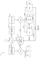
- FIG. 6 is an electrical block diagram of a fixture control according to one embodiment.
- FIG. 7 is a graphical user interface for a recipe application display according to one embodiment.
- FIG. 8 is another graphical user interface for a recipe application display according to one embodiment.
- FIG. 9 is another graphical user interface for a recipe application display according to one embodiment.
- FIG. 10 is a flow diagram of a method for generating a recipe application startup platform.
- FIG. 11 is a flow diagram of a method for launching a recipe application.
- FIG. 12 is a flow diagram of a method for adding, changing, or deleting a recipe in a recipe application.
- FIG. 13 is a flow diagram of a method for Bluetooth initialization and data transmission in the recipe application.
- FIG. 14 is a flow diagram of a method for managing Bluetooth communication in a recipe application.
- FIG. 15 is a communication block diagram.
- FIG. 16 is a flow diagram of a method for controlling a fixture mesh network using a user operated device.
- Embodiments presented herein relate to an array of different colored light emitting diodes (LEDs) operating at various peak wavelengths in a horticultural light.
- a user may control the light intensity of each LED color group in the horticultural light to produce an appropriate light mix output that optimizes different stages of plant growth.
- the lighting fixture includes a housing fixture having an outer surface including an opening.
- the lighting fixture includes an array of different colored light emitting diodes (LEDs) operating at various peak wavelengths.
- the lighting fixture includes a current control channel in electrical communication with at least one of the LEDs.
- the lighting fixture includes a fixture control for controlling light wave intensity of each LED via the current control channel.
- the lighting fixture includes a fixture firmware to store programmable user input.
- the lighting fixture includes a fixture ID to identify the housing fixture in a system of horticultural lights.
- the system includes a plurality of horticultural lights, each consisting a housing fixture and an array of different colored light emitting diodes (LEDs).
- the system includes a plurality of current control channels in electrical communication with at least one of the LEDs.
- the system includes a plurality of fixture controls for controlling light wave intensity of each LED via the current control channel.
- the system includes a fixture mesh network including at least one fixture control.
- the system includes an at least one master fixture control for receiving information from a user and relaying the information to other fixture control(s) in the fixture mesh network.
- the system includes a plurality of fixture firmware consisting one or more zone control variable, the one or more user input recipe, and multiple preset modes of operation.
- Another example embodiment provides a method for programming a horticultural light.
- the method includes receiving a user input including intensity level for at least one LED color group.
- the method includes transmitting the user input to a fixture control.
- the method includes relaying information between a network of at least one fixture controls.
- the method includes, based on the relayed information, controlling a wavelength intensity of a light emitting diode (LED) to produce a desirable colored light.
- LED light emitting diode
- embodiments of the invention may include hardware, software, and electronic components or modules that, for purposes of discussion, may be illustrated and described as if the majority of the components were implemented solely in hardware.
- the electronic-based aspects of the invention may be implemented in software (e.g., stored on non-transitory computer-readable medium) executable by one or more processors.
- control units and “controllers” described in the specification can include one or more processors, one or more memory modules including non-transitory computer-readable medium, one or more input/output interfaces, and various connections (e.g., a system bus) connecting the components.
- FIG. 1 and FIG. 2 illustrate a horticultural light 10 .
- the horticultural light 10 includes a linear aluminum housing fixture 4 .
- the housing fixture 4 is shaped differently.
- the housing 4 includes accessories 8 (e.g., a male or female connector) to engage a similar housing fixture 4 so that multiple units may be coupled together for a larger illumination area.
- the housing fixture 4 has an outer surface including an opening 11 , through which an array 12 may protrude.
- Each horticultural light 10 has an array 12 (See FIG. 1 ) of different LED color groups, a current control channel (e.g., the power converters 32 of FIG. 6 ) in electrical communication with at least one LED color group, a current measuring device 13 (See FIG. 4 ) to detect the current flow through each LED color group, a fixture control 20 (See FIG. 6 ) for modifying light wave intensity of the LED color groups (e.g., based on instructions from a user), and a programmable fixture firmware installed on each fixture control 20 .
- a plurality of fixture controls 20 in a system of horticultural lights form a fixture mesh network (See FIG. 15 ).
- the user may specify and store a recipe that contains a specific combination of intensity levels for each LED color group in the fixture firmware.
- a master fixture control receives user recipes and relays the information to other fixture controls via the fixture mesh network.
- a communication bridge is coupled to the master fixture control to bridge between various networks which allows for more flexibility.
- Each horticultural light in a system may be assigned a control zone variable that identifies the location of the horticultural light in the instance that the user assigns different sections of horticultural lights to operate at different recipes.
- the fixture firmware may store control zone variables, user recipes, and multiple factory preset modes of operation.
- FIG. 3 includes specifications for the LED color groups according to one embodiment, including type, color, peak wavelength, number of LEDs, current, voltage, and power.
- the LED color groups may be red, blue, white, ultraviolet, infrared, or another suitable color band.
- the color of a LED depends on the peak wavelength specification of the LED. For example, a blue LED operates at a peak wavelength between 450 to 500 nm while a red LED operates at peak wavelength between 610 to 760 nm.
- the amount of power supplied to a LED determines the light intensity of the produced colored light. Highly powered 5000K white LEDs may be used individually in “inspection mode” or in combination with LEDs operating at specific wavelengths in “growth mode.”
- LEDs are more power efficient and have significantly longer lifespans than most traditional bulbs.
- FIG. 4 illustrates a circuit diagram for the LED board 12 according to one embodiment.
- groups of LEDs 16 operating at the same peak wavelength are wired in series in common LED color groups 18
- LEDs operating at different peak wavelengths are wired in parallel in separate LED color groups 18 . Since current is the same for elements wired in series, this wiring configuration allows for “dimming” or “brightening” of each LED color group 18 independently of the other LED color groups 18 .
- a current measuring device 13 detects current flow through each LED color group 18 .
- the current measuring device detects a fault in a single LED driver or an LED color group 18 , and instances in which a single LED color group 18 receives zero current may be reported or transmitted to the fixture mesh network.
- Such fault detection provides improved detection of failures especially failures that may not be visually apparent, such as in the case of an infrared LED failure.
- the horticultural light has two LED boards 12 .
- FIG. 5 illustrates a wiring diagram for an example horticultural light 10 .
- An AC input voltage 24 is transmitted to a constant voltage (CV) driver 28 .
- the CV driver 28 provides power to a driver PCB 29 .
- An interface 37 is coupled to the LED boards 12 and the driver PCB 29 .
- the interface 37 receives recipes from the user.
- the interface 37 provides interfaces to other modules to allow the fixture to communicate with other fixtures and outside devices, such as smart phones or other computing devices.
- the interface 37 includes a Bluetooth interface 19 a , a radio frequency (RF) interface 19 b , and a NXFM interface 19 c .
- Alternative embodiments may provide other suitable interfaces.
- FIG. 6 is a block diagram for an example horticultural light 10 .
- the CV driver 28 powers a fixture control 20 .
- the fixture control 20 includes power converters 32 and a control module 36 with an interface 37 (See FIG. 5 ).
- the interface 37 receives recipes from the user, and the control module 20 transmits a signal to each power converter 32 to supply a corresponding power and current to each LED color group 18 .
- the user has the option to leave certain LED color groups 18 disabled to achieve a more flexible range of light mix outputs.
- FIGS. 7 - 9 illustrate screenshots of a recipe application 39 for generating recipes, according to one embodiment.
- a welcome page of the application may include a list 40 of user stored recipes 40 a .
- a light-bulb icon 44 may be displayed next to the recipe 40 a that is currently applied to the horticultural light(s).
- a plus sign 48 (e.g., positioned in the upper right hand corner) may allow the user to add a new recipe 40 a to the list 40 .
- Selecting a recipe 40 a may direct the user to a second page ( FIG. 8 ) to edit the recipe 40 a .
- the user may be prompted to enter a “Recipe name” 52 (e.g., in ASCII characters including upper case, lower case, blank, and underline characters). As shown in FIG. 9 , the user may enter in a dim level 56 in percentages ranging from 30% to 100% to set the light intensity of each LED color group 18 . After the desired adjustments have been made, the user may choose to “Save” 60 , “Cancel” 61 , “Delete” 62 , or “Send” 63 the recipe (see FIG. 8 ). Saving may add the recipe 40 a to the list 40 of stored user recipes displayed in FIG. 7 . Canceling may erase user input information and return to the welcome page. Deleting may remove a previously stored recipe 40 a from the list 40 . Sending may deliver the user recipe 40 a to another user.
- a “Recipe name” 52 e.g., in ASCII characters including upper case, lower case, blank, and underline characters.
- the user may enter in a dim level 56 in percentage
- the application when the recipe application 39 is launched, the application follows a sequence of events to configure a platform and handle new “events” or user recipes 40 a .
- the application may be executed on a smart phone, tablet computer, or other computing device in communication with the lighting fixture 10 .
- FIG. 10 illustrates a flowchart of an example method 100 for a startup platform of one embodiment for loading the recipe application 39 .
- the application loads the forms for a graphical user interface (at block 102 ).
- FIG. 11 illustrates a flowchart of an example method 110 for saving received recipes 40 a , according to one embodiment.
- the application instance is launched and the variables are initialized.
- the application waits for an event, for example, for the user to select a command via the graphical user interface.
- events are handled based on the nature of the events. For example, when no event is received within a determined time, the application sleeps and automatically saves the current recipe (at block 120 ).
- the application starts up by displaying a main screen (at block 122 ).
- the application resumes from where it was left off by navigating to the last known screen (at block 124 ) by determining the screen (at block 126 ).
- the screen may be the main screen (block 122 ) or the recipe detail screen (See FIGS. 8 and 9 ), at block 128 .
- FIG. 12 illustrates a flowchart of a method 130 for adding, changing, or deleting a recipe 40 a , according to one embodiment.
- a user action is received and the application enters an edit mode (at block 134 ), an add mode (at block 136 ), or it returns to displaying the main screen (See FIG. 7 ) including a recipe list (at block 138 ).
- entries are validated (at block 140 ) for example, based on the configuration of the lighting fixture 10 , and may be saved (at block 142 ), sent (at block 144 ), or deleted (at block 146 ).
- FIG. 13 illustrates a flowchart for a method 150 for enabling Bluetooth communication and transmitting information from the recipe application 39 to a paired device.
- the paired device is the master fixture control 20 .
- the application determines whether a connection exists. When a connection exists, the application determines whether there is data to send, at block 154 . When there is data to send, it is sent, at block 156 , and the application returns to the graphical user interface, at block 158 . When there is no data to send, the application returns to the graphical user interface, at block 158 . When a connection does not exist, the application determines whether the Bluetooth adapter is enabled, at block 160 .
- the application looks for a paired device, at block 162 .
- the application returns to the graphical user interface, at block 158 .
- the application opens a connection, at block 166 , and determines whether there is data to send, at block 154 .
- the application issue a request to enable the adapter, at block 168 .
- the application looks for a paired device, at block 162 .
- the application returns to the graphical user interface, at block 158 .
- FIG. 14 illustrates a flowchart of a method 180 for processing and updating transmitted information in the recipe application 39 .
- Bluetooth is running and receiving data as a background process.
- the application listens for incoming data. When data is not received, at block 186 , the application continues to listen, at block 184 .
- the application parses the data, at block 188 .
- the application invokes the data package, at block 192 , and updates the GUI and database based on the data package, at block 194 .
- the application continues to listen for data at block 184 .
- the master fixture control 20 may receive user recipes 40 a via a hand-held device (for example, a smart phone), a computer, or another computing device.
- a smart phone 68 operating the recipe application 39 transmits information via Bluetooth to the master fixture control 20 .
- the signal is transmitted to the master fixture control 20 via a universal asynchronous receiver/transmitter (UART).
- UART universal asynchronous receiver/transmitter
- the fixture control module 20 uses the recipe 40 a to regulate current flow to each LED color group 18 to produce a desired light mix output, as specified in the recipe 40 a.
- only the fixture control 20 to be updated will receive the user recipe 40 a and will make adjustments to the light mix output.
- the user recipe 40 a is not transmitted to the other fixture control(s) 20 in communication with the fixture mesh network 76 .
- the master fixture control 20 transmits the user recipes 40 a to other fixture control(s) 20 in the system of horticultural lights in communication with the fixture mesh network. Accordingly, a user may control multiple horticultural lights in different zones to operate under different recipes as opposed to all horticultural lights outputting the same light mix.
- a personal computer (PC) 72 including a fixture control application, for example, the application 39 may send a signal to the fixture mesh network 76 via a USB bridge node (not shown).
- the USB Bridge includes a USB port and an antenna that transmits information from the PC 72 to the fixture mesh network module 76 .
- the fixture control 20 connects to the fixture mesh network module 76 .
- the fixture control 20 adjusts the light mix output and updates the recipe 40 a in the fixture firmware based on the user input, for example, located within a zone specified by the use.
- Firmware may store one or more zone control variables, one or more user input recipes, and multiple preset modes of operation.
- the recipe 40 a is stored in nonvolatile memory, thus retaining stored recipe information in the event of a power outage.
- a different type of networks 19 could be used to transmit information from the PC 72 to the fixture control(s) 20 .
- Horticultural lights may be controlled individually, a group of horticultural lights may be controlled according to zone specifications, or all horticultural lights may be controlled in unison. If a user chooses to control the system of horticultural lights according to zones, the system performs a test to confirm whether a located fixture control 20 is the fixture control 20 specified by the user.
- FIG. 16 illustrates a flowchart of a commissioning method 200 for determining which fixture control(s) 20 in a fixture mesh network 76 to update with a recipe 40 a . In some embodiments, commissioning may depend on the type of device that transmits recipe information to the fixture control(s).
- the smart phone 68 or the computer 72 transmit recipes to the mesh network modules 76 , 76 a , as described above.
- the mesh network module 76 receives the message and determines whether it is addressed locally or remotely, at block 206 .
- the mesh network module 76 a determines, at block 208 , whether the message is addressed to it.
- the message is addressed to that lighting fixture and module, at block 210 , the message is processed by the network module, at block 212 .
- the message is processed by the network module, at block 216 .
Landscapes
- Life Sciences & Earth Sciences (AREA)
- Biodiversity & Conservation Biology (AREA)
- Botany (AREA)
- Ecology (AREA)
- Forests & Forestry (AREA)
- Environmental Sciences (AREA)
- Engineering & Computer Science (AREA)
- Computer Networks & Wireless Communication (AREA)
- Circuit Arrangement For Electric Light Sources In General (AREA)
Abstract
Description
Claims (28)
Priority Applications (2)
| Application Number | Priority Date | Filing Date | Title |
|---|---|---|---|
| US18/449,985 US12295302B2 (en) | 2016-07-08 | 2023-08-15 | Horticultural light |
| US19/176,754 US20250234814A1 (en) | 2016-07-08 | 2025-04-11 | Horticultural light |
Applications Claiming Priority (3)
| Application Number | Priority Date | Filing Date | Title |
|---|---|---|---|
| US201662360077P | 2016-07-08 | 2016-07-08 | |
| US15/645,565 US20180014374A1 (en) | 2016-07-08 | 2017-07-10 | Horticultural light |
| US18/449,985 US12295302B2 (en) | 2016-07-08 | 2023-08-15 | Horticultural light |
Related Parent Applications (1)
| Application Number | Title | Priority Date | Filing Date |
|---|---|---|---|
| US15/645,565 Continuation US20180014374A1 (en) | 2016-07-08 | 2017-07-10 | Horticultural light |
Related Child Applications (1)
| Application Number | Title | Priority Date | Filing Date |
|---|---|---|---|
| US19/176,754 Continuation US20250234814A1 (en) | 2016-07-08 | 2025-04-11 | Horticultural light |
Publications (2)
| Publication Number | Publication Date |
|---|---|
| US20240196809A1 US20240196809A1 (en) | 2024-06-20 |
| US12295302B2 true US12295302B2 (en) | 2025-05-13 |
Family
ID=60911334
Family Applications (3)
| Application Number | Title | Priority Date | Filing Date |
|---|---|---|---|
| US15/645,565 Abandoned US20180014374A1 (en) | 2016-07-08 | 2017-07-10 | Horticultural light |
| US18/449,985 Active US12295302B2 (en) | 2016-07-08 | 2023-08-15 | Horticultural light |
| US19/176,754 Pending US20250234814A1 (en) | 2016-07-08 | 2025-04-11 | Horticultural light |
Family Applications Before (1)
| Application Number | Title | Priority Date | Filing Date |
|---|---|---|---|
| US15/645,565 Abandoned US20180014374A1 (en) | 2016-07-08 | 2017-07-10 | Horticultural light |
Family Applications After (1)
| Application Number | Title | Priority Date | Filing Date |
|---|---|---|---|
| US19/176,754 Pending US20250234814A1 (en) | 2016-07-08 | 2025-04-11 | Horticultural light |
Country Status (1)
| Country | Link |
|---|---|
| US (3) | US20180014374A1 (en) |
Families Citing this family (14)
| Publication number | Priority date | Publication date | Assignee | Title |
|---|---|---|---|---|
| US11006493B1 (en) | 2018-05-29 | 2021-05-11 | Juganu Ltd. | Lighting systems for general illumination and disinfection |
| GB2583881A (en) * | 2020-08-24 | 2020-11-11 | Juganu Ltd | Lighting systems for general illumination and disinfection |
| US11391439B2 (en) | 2018-05-29 | 2022-07-19 | Juganu Ltd. | Lighting systems for general illumination and disinfection |
| WO2020177003A1 (en) * | 2019-03-05 | 2020-09-10 | Ciencia Pura Spa | Flexible led lighting system for homogeneously lighting a horizontal plane and its use in cultivating plants in enclosed spaces such as greenhouses and plant propagation laboratories |
| US11402089B2 (en) | 2019-06-06 | 2022-08-02 | Abundant Lighting Technology, Llc | LED growth light |
| EP4005349A4 (en) * | 2019-07-24 | 2023-07-05 | Sollum Technologies Inc. | METHODS, SYSTEMS AND ASSEMBLIES FOR COMPLETING THE SPECTRAL CONTENT OF A LIGHT WITH A NON-VISIBLE LIGHT |
| WO2021023024A1 (en) * | 2019-08-07 | 2021-02-11 | 李许可 | Plant growth illumination device capable of preventing and controlling disease and insect pest, and control method therefor |
| WO2021191681A1 (en) * | 2020-03-23 | 2021-09-30 | Juganu Ltd. | Lighting systems for general illumination and disinfection |
| DE102020133237A1 (en) | 2020-12-11 | 2022-06-15 | Dh Licht Gmbh | LED circuit board module for providing a photobiologically active full spectrum |
| US11737396B2 (en) | 2020-12-28 | 2023-08-29 | Seoul Viosys Co., Ltd. | Light module for plant cultivation and plant cultivation apparatus including the same |
| US11805173B2 (en) * | 2021-05-05 | 2023-10-31 | Fluence Bioengineering, Inc. | Wireless network for horticultural systems |
| USD980808S1 (en) * | 2021-06-19 | 2023-03-14 | Hgci, Inc. | Horticultural lighting controller |
| USD980173S1 (en) * | 2022-05-09 | 2023-03-07 | Hgci, Inc. | Horticultural lighting controller |
| US12215855B2 (en) | 2022-07-20 | 2025-02-04 | Abundant Lighting Technology, Llc | LED growth light |
Citations (27)
| Publication number | Priority date | Publication date | Assignee | Title |
|---|---|---|---|---|
| US20020145394A1 (en) | 2000-08-07 | 2002-10-10 | Frederick Morgan | Systems and methods for programming illumination devices |
| US20020195975A1 (en) | 2001-03-13 | 2002-12-26 | Schanberger Eric K. | Systems and methods for synchronizing lighting effects |
| US20030028260A1 (en) | 1999-07-14 | 2003-02-06 | Blackwell Michael K. | Systems and methods for controlling programmable lighting systems |
| US20040052076A1 (en) * | 1997-08-26 | 2004-03-18 | Mueller George G. | Controlled lighting methods and apparatus |
| US20040109302A1 (en) | 2001-02-28 | 2004-06-10 | Kenji Yoneda | Method of cultivating plant and illuminator for cultivating plant |
| US20070253196A1 (en) | 2006-04-27 | 2007-11-01 | Pfo Lighting | LED aquarium light |
| US20080122376A1 (en) | 2006-11-10 | 2008-05-29 | Philips Solid-State Lighting Solutions | Methods and apparatus for controlling series-connected leds |
| US7573729B2 (en) | 2003-11-13 | 2009-08-11 | Koninklijke Philips Electronics N.V. | Resonant power LED control circuit with brightness and color control |
| US20110018465A1 (en) | 2008-01-17 | 2011-01-27 | Koninklijke Philips Electronics N.V. | Method and apparatus for light intensity control |
| KR20110022410A (en) | 2009-08-27 | 2011-03-07 | (주)태종씨앤아이 | Plant Cultivation Management System |
| US20110209400A1 (en) | 2007-08-15 | 2011-09-01 | Lemnis Lighting Patent Holding B.V. | Led lighting device for growing plants |
| US20120170264A1 (en) | 2011-01-03 | 2012-07-05 | Cammie Mckenzie | Omnispectrum led grow light |
| US20130229123A1 (en) | 2012-03-03 | 2013-09-05 | Tain-Rein Chen | Lighting-dimming device chopping power waveforms for adjusting brightness |
| US8723766B2 (en) | 2007-09-21 | 2014-05-13 | Point Somee Limited Liability Company | System and apparatus for regulation of wavelength shift and perceived color of solid state lighting with intensity and temperature variation |
| US20140152194A1 (en) | 2012-11-27 | 2014-06-05 | James H. Beyer | Light emitting diode grow light for plant growing applications |
| US8933638B2 (en) | 2011-05-15 | 2015-01-13 | Lighting Science Group Corporation | Programmable luminaire and programmable luminaire system |
| US8975825B2 (en) | 2012-05-08 | 2015-03-10 | Cree, Inc. | Light emitting diode driver with isolated control circuits |
| US9131578B2 (en) | 2013-07-16 | 2015-09-08 | General Electric Company | Programmable light emitting diode (LED) driver technique based upon an input voltage signal |
| US9137874B2 (en) | 2011-12-02 | 2015-09-15 | Biological Illumination, Llc | Illumination and grow light system and associated methods |
| US20150289328A1 (en) | 2014-04-04 | 2015-10-08 | iUNU, LLC | Lighting fixture with application controller |
| US9179527B2 (en) | 2013-07-16 | 2015-11-03 | General Electric Company | Programmable light emitting diode (LED) driver technique based upon a prefix signal |
| US9189996B2 (en) | 2013-12-17 | 2015-11-17 | Ephesus Lighting, Inc. | Selectable, zone-based control for high intensity LED illumination system |
| US20160064204A1 (en) | 2014-09-02 | 2016-03-03 | iUNU, LLC | Intelligent Radio-Controlled Plasma Light |
| US20160095194A1 (en) | 2014-09-29 | 2016-03-31 | Mitsubishi Electric Corporation | Light source control apparatus and light source control method |
| US20160120010A1 (en) | 2014-10-24 | 2016-04-28 | Express Imaging Systems, Llc | Detection and correction of faulty photo controls in outdoor luminaires |
| US20160262313A1 (en) | 2015-03-09 | 2016-09-15 | LED Living Technology | Lighting System for Promoting the Rapid Maturation of Commercial Plants |
| US20170241632A1 (en) | 2016-02-19 | 2017-08-24 | Ken Nguyen | Led lighting system and opertaing method for irradiation of plants |
Family Cites Families (1)
| Publication number | Priority date | Publication date | Assignee | Title |
|---|---|---|---|---|
| DE102012013039B4 (en) * | 2012-06-29 | 2020-07-23 | Diehl Aerospace Gmbh | Lighting device and method for operating the lighting device in a dimming mode |
-
2017
- 2017-07-10 US US15/645,565 patent/US20180014374A1/en not_active Abandoned
-
2023
- 2023-08-15 US US18/449,985 patent/US12295302B2/en active Active
-
2025
- 2025-04-11 US US19/176,754 patent/US20250234814A1/en active Pending
Patent Citations (27)
| Publication number | Priority date | Publication date | Assignee | Title |
|---|---|---|---|---|
| US20040052076A1 (en) * | 1997-08-26 | 2004-03-18 | Mueller George G. | Controlled lighting methods and apparatus |
| US20030028260A1 (en) | 1999-07-14 | 2003-02-06 | Blackwell Michael K. | Systems and methods for controlling programmable lighting systems |
| US20020145394A1 (en) | 2000-08-07 | 2002-10-10 | Frederick Morgan | Systems and methods for programming illumination devices |
| US20040109302A1 (en) | 2001-02-28 | 2004-06-10 | Kenji Yoneda | Method of cultivating plant and illuminator for cultivating plant |
| US20020195975A1 (en) | 2001-03-13 | 2002-12-26 | Schanberger Eric K. | Systems and methods for synchronizing lighting effects |
| US7573729B2 (en) | 2003-11-13 | 2009-08-11 | Koninklijke Philips Electronics N.V. | Resonant power LED control circuit with brightness and color control |
| US20070253196A1 (en) | 2006-04-27 | 2007-11-01 | Pfo Lighting | LED aquarium light |
| US20080122376A1 (en) | 2006-11-10 | 2008-05-29 | Philips Solid-State Lighting Solutions | Methods and apparatus for controlling series-connected leds |
| US20110209400A1 (en) | 2007-08-15 | 2011-09-01 | Lemnis Lighting Patent Holding B.V. | Led lighting device for growing plants |
| US8723766B2 (en) | 2007-09-21 | 2014-05-13 | Point Somee Limited Liability Company | System and apparatus for regulation of wavelength shift and perceived color of solid state lighting with intensity and temperature variation |
| US20110018465A1 (en) | 2008-01-17 | 2011-01-27 | Koninklijke Philips Electronics N.V. | Method and apparatus for light intensity control |
| KR20110022410A (en) | 2009-08-27 | 2011-03-07 | (주)태종씨앤아이 | Plant Cultivation Management System |
| US20120170264A1 (en) | 2011-01-03 | 2012-07-05 | Cammie Mckenzie | Omnispectrum led grow light |
| US8933638B2 (en) | 2011-05-15 | 2015-01-13 | Lighting Science Group Corporation | Programmable luminaire and programmable luminaire system |
| US9137874B2 (en) | 2011-12-02 | 2015-09-15 | Biological Illumination, Llc | Illumination and grow light system and associated methods |
| US20130229123A1 (en) | 2012-03-03 | 2013-09-05 | Tain-Rein Chen | Lighting-dimming device chopping power waveforms for adjusting brightness |
| US8975825B2 (en) | 2012-05-08 | 2015-03-10 | Cree, Inc. | Light emitting diode driver with isolated control circuits |
| US20140152194A1 (en) | 2012-11-27 | 2014-06-05 | James H. Beyer | Light emitting diode grow light for plant growing applications |
| US9131578B2 (en) | 2013-07-16 | 2015-09-08 | General Electric Company | Programmable light emitting diode (LED) driver technique based upon an input voltage signal |
| US9179527B2 (en) | 2013-07-16 | 2015-11-03 | General Electric Company | Programmable light emitting diode (LED) driver technique based upon a prefix signal |
| US9189996B2 (en) | 2013-12-17 | 2015-11-17 | Ephesus Lighting, Inc. | Selectable, zone-based control for high intensity LED illumination system |
| US20150289328A1 (en) | 2014-04-04 | 2015-10-08 | iUNU, LLC | Lighting fixture with application controller |
| US20160064204A1 (en) | 2014-09-02 | 2016-03-03 | iUNU, LLC | Intelligent Radio-Controlled Plasma Light |
| US20160095194A1 (en) | 2014-09-29 | 2016-03-31 | Mitsubishi Electric Corporation | Light source control apparatus and light source control method |
| US20160120010A1 (en) | 2014-10-24 | 2016-04-28 | Express Imaging Systems, Llc | Detection and correction of faulty photo controls in outdoor luminaires |
| US20160262313A1 (en) | 2015-03-09 | 2016-09-15 | LED Living Technology | Lighting System for Promoting the Rapid Maturation of Commercial Plants |
| US20170241632A1 (en) | 2016-02-19 | 2017-08-24 | Ken Nguyen | Led lighting system and opertaing method for irradiation of plants |
Non-Patent Citations (6)
| Title |
|---|
| 892 Form dated Apr. 21, 2021 which was received in connection with U.S. Appl. No. 15/645,565. |
| 892 Form dated Aug. 25, 2021 which was received in connection with U.S. Appl. No. 15/645,565. |
| 892 Form dated Feb. 10, 2020 which was received in connection with U.S. Appl. No. 15/645,565. |
| 892 Form dated May 23, 2022 which was received in connection with U.S. Appl. No. 15/645,565. |
| 892 Form dated Oct. 5, 2022 which was received in connection with U.S. Appl. No. 15/645,565. |
| Information Disclosure Form dated Jul. 11, 2017 which was filed in connection with U.S. Appl. No. 15/645,565. |
Also Published As
| Publication number | Publication date |
|---|---|
| US20180014374A1 (en) | 2018-01-11 |
| US20240196809A1 (en) | 2024-06-20 |
| US20250234814A1 (en) | 2025-07-24 |
Similar Documents
| Publication | Publication Date | Title |
|---|---|---|
| US12295302B2 (en) | Horticultural light | |
| US8110996B2 (en) | Modular wireless lighting control system using a common ballast control interface | |
| US8471492B2 (en) | Wireless adaptation of lighting power supply | |
| US11012534B2 (en) | Node for a multi-hop communication network, related lighting system, method of updating the software of lighting modules and computer-program product | |
| KR101638441B1 (en) | System for controlling lighting of classroom | |
| KR101584936B1 (en) | LED illumination device | |
| CN103024975A (en) | Light control device, light control method and illuminating device | |
| US20150137708A1 (en) | Light Control System and Light Control Method Thereof | |
| JP2013521171A (en) | Aircraft LED washlight system and control method thereof | |
| US9380664B2 (en) | Microcontroller burst mode to maintain voltage supply during standby mode of a lighting system | |
| JP7507428B2 (en) | Lighting system, lighting fixture, and lighting system | |
| US20100237803A1 (en) | Dimmable color selectable light emitting diodes | |
| US11317442B2 (en) | Non-coordinated back-off timer assignment | |
| US20200170089A1 (en) | Power supply system for a lighting system | |
| US20130002168A1 (en) | Programmable solid state illuminating system and the controlling method thereof | |
| US20210014952A1 (en) | System and method for automated light level and daylight harvesting calibration using mobile handheld devices | |
| KR101698346B1 (en) | An ac wall switch performing led lights controls without supplemental power wires | |
| KR20190023240A (en) | Light system capable of adjusting brightness, color temperature and saturation value | |
| JP6038579B2 (en) | Light control system, light control method, and lighting device | |
| US9781796B1 (en) | Brightness control system for decorative light strings | |
| US9713230B2 (en) | Method for controlling a lamp having a plurality of sub-units | |
| JP7661563B2 (en) | Lighting fixtures and lighting systems | |
| US20260025895A1 (en) | Configuration of a load control device for a light-emitting diode light source | |
| JP2014096287A (en) | Illumination apparatus, dimming and color matching method, and dimming and color matching system | |
| US10886696B2 (en) | Mixed and distributed laser illumination system |
Legal Events
| Date | Code | Title | Description |
|---|---|---|---|
| FEPP | Fee payment procedure |
Free format text: ENTITY STATUS SET TO UNDISCOUNTED (ORIGINAL EVENT CODE: BIG.); ENTITY STATUS OF PATENT OWNER: LARGE ENTITY |
|
| AS | Assignment |
Owner name: HLI SOLUTIONS, INC., SOUTH CAROLINA Free format text: CHANGE OF NAME;ASSIGNOR:HUBBELL LIGHTING, INC.;REEL/FRAME:064728/0877 Effective date: 20220216 Owner name: HUBBELL INCORPOATED, CONNECTICUT Free format text: ASSIGNMENT OF ASSIGNORS INTEREST;ASSIGNORS:RHODES, BRUCE;KOLENDA, PAUL;GHEORGE, BOGDAN;AND OTHERS;SIGNING DATES FROM 20180119 TO 20180125;REEL/FRAME:064705/0280 Owner name: CURRENT LIGHTING SOLUTIONS, LLC, OHIO Free format text: ASSIGNMENT OF ASSIGNORS INTEREST;ASSIGNOR:HLI SOLUTIONS, INC.;REEL/FRAME:064705/0898 Effective date: 20230824 Owner name: HUBBELL LIGHTING, INC., CONNECTICUT Free format text: NUNC PRO TUNC ASSIGNMENT;ASSIGNOR:HUBBELL INCORPOATED;REEL/FRAME:064705/0751 Effective date: 20220112 |
|
| AS | Assignment |
Owner name: HUBBELL LIGHTING, INC., CONNECTICUT Free format text: CORRECTIVE ASSIGNMENT TO CORRECT THE CONVEYING PARTY'S NAME PREVIOUSLY RECORDED AT REEL: 064705 FRAME: 0751. ASSIGNOR(S) HEREBY CONFIRMS THE ASSIGNMENT;ASSIGNOR:HUBBELL INCORPORATED;REEL/FRAME:064733/0704 Effective date: 20220112 Owner name: HUBBELL INCORPORATED, CONNECTICUT Free format text: CORRECTIVE ASSIGNMENT TO CORRECT THE RECEIVING PARTY NAME PREVIOUSLY RECORDED ON REEL 064705 FRAME 0280. ASSIGNOR(S) HEREBY CONFIRMS THE ASSIGNMENT;ASSIGNORS:RHODES, BRUCE;KOLENDA, PAUL;GHEORGE, BOGDAN;AND OTHERS;SIGNING DATES FROM 20180119 TO 20180125;REEL/FRAME:064730/0936 |
|
| AS | Assignment |
Owner name: CURRENT LIGHTING SOLUTIONS, LLC, OHIO Free format text: PARTIAL RELEASE OF FIRST LIEN SECURITY INTEREST;ASSIGNOR:ALLY BANK, AS AGENT;REEL/FRAME:066291/0626 Effective date: 20240112 |
|
| AS | Assignment |
Owner name: CURRENT LIGHTING SOLUTIONS, LLC, OHIO Free format text: PARTIAL RELEASE OF SECOND LIEN SECURITY INTEREST;ASSIGNOR:ATLANTIC PARK STRATEGIC CAPITAL FUND, L.P., AS COLLATERAL AGENT;REEL/FRAME:066341/0089 Effective date: 20240112 |
|
| AS | Assignment |
Owner name: ABL IP HOLDING LLC, GEORGIA Free format text: ASSIGNMENT OF ASSIGNORS INTEREST;ASSIGNOR:CURRENT LIGHTING SOLUTIONS, LLC;REEL/FRAME:066414/0634 Effective date: 20240119 |
|
| STPP | Information on status: patent application and granting procedure in general |
Free format text: NON FINAL ACTION MAILED |
|
| STPP | Information on status: patent application and granting procedure in general |
Free format text: RESPONSE TO NON-FINAL OFFICE ACTION ENTERED AND FORWARDED TO EXAMINER |
|
| STPP | Information on status: patent application and granting procedure in general |
Free format text: NOTICE OF ALLOWANCE MAILED -- APPLICATION RECEIVED IN OFFICE OF PUBLICATIONS |
|
| STCF | Information on status: patent grant |
Free format text: PATENTED CASE |