US12295257B2 - Organic electroluminescence device and polycyclic compound for same - Google Patents
Organic electroluminescence device and polycyclic compound for same Download PDFInfo
- Publication number
- US12295257B2 US12295257B2 US17/010,424 US202017010424A US12295257B2 US 12295257 B2 US12295257 B2 US 12295257B2 US 202017010424 A US202017010424 A US 202017010424A US 12295257 B2 US12295257 B2 US 12295257B2
- Authority
- US
- United States
- Prior art keywords
- formula
- group
- substituted
- carbon atoms
- compound
- Prior art date
- Legal status (The legal status is an assumption and is not a legal conclusion. Google has not performed a legal analysis and makes no representation as to the accuracy of the status listed.)
- Active, expires
Links
Images


Classifications
-
- C—CHEMISTRY; METALLURGY
- C09—DYES; PAINTS; POLISHES; NATURAL RESINS; ADHESIVES; COMPOSITIONS NOT OTHERWISE PROVIDED FOR; APPLICATIONS OF MATERIALS NOT OTHERWISE PROVIDED FOR
- C09K—MATERIALS FOR MISCELLANEOUS APPLICATIONS, NOT PROVIDED FOR ELSEWHERE
- C09K11/00—Luminescent materials, e.g. electroluminescent or chemiluminescent
- C09K11/06—Luminescent materials, e.g. electroluminescent or chemiluminescent containing organic luminescent materials
-
- C—CHEMISTRY; METALLURGY
- C07—ORGANIC CHEMISTRY
- C07D—HETEROCYCLIC COMPOUNDS
- C07D491/00—Heterocyclic compounds containing in the condensed ring system both one or more rings having oxygen atoms as the only ring hetero atoms and one or more rings having nitrogen atoms as the only ring hetero atoms, not provided for by groups C07D451/00 - C07D459/00, C07D463/00, C07D477/00 or C07D489/00
- C07D491/02—Heterocyclic compounds containing in the condensed ring system both one or more rings having oxygen atoms as the only ring hetero atoms and one or more rings having nitrogen atoms as the only ring hetero atoms, not provided for by groups C07D451/00 - C07D459/00, C07D463/00, C07D477/00 or C07D489/00 in which the condensed system contains two hetero rings
- C07D491/06—Peri-condensed systems
-
- C—CHEMISTRY; METALLURGY
- C07—ORGANIC CHEMISTRY
- C07B—GENERAL METHODS OF ORGANIC CHEMISTRY; APPARATUS THEREFOR
- C07B59/00—Introduction of isotopes of elements into organic compounds ; Labelled organic compounds per se
- C07B59/001—Acyclic or carbocyclic compounds
-
- C—CHEMISTRY; METALLURGY
- C07—ORGANIC CHEMISTRY
- C07D—HETEROCYCLIC COMPOUNDS
- C07D498/00—Heterocyclic compounds containing in the condensed system at least one hetero ring having nitrogen and oxygen atoms as the only ring hetero atoms
- C07D498/02—Heterocyclic compounds containing in the condensed system at least one hetero ring having nitrogen and oxygen atoms as the only ring hetero atoms in which the condensed system contains two hetero rings
- C07D498/06—Peri-condensed systems
-
- C—CHEMISTRY; METALLURGY
- C07—ORGANIC CHEMISTRY
- C07D—HETEROCYCLIC COMPOUNDS
- C07D513/00—Heterocyclic compounds containing in the condensed system at least one hetero ring having nitrogen and sulfur atoms as the only ring hetero atoms, not provided for in groups C07D463/00, C07D477/00 or C07D499/00 - C07D507/00
- C07D513/02—Heterocyclic compounds containing in the condensed system at least one hetero ring having nitrogen and sulfur atoms as the only ring hetero atoms, not provided for in groups C07D463/00, C07D477/00 or C07D499/00 - C07D507/00 in which the condensed system contains two hetero rings
- C07D513/06—Peri-condensed systems
-
- C—CHEMISTRY; METALLURGY
- C07—ORGANIC CHEMISTRY
- C07F—ACYCLIC, CARBOCYCLIC OR HETEROCYCLIC COMPOUNDS CONTAINING ELEMENTS OTHER THAN CARBON, HYDROGEN, HALOGEN, OXYGEN, NITROGEN, SULFUR, SELENIUM OR TELLURIUM
- C07F7/00—Compounds containing elements of Groups 4 or 14 of the Periodic Table
- C07F7/02—Silicon compounds
- C07F7/08—Compounds having one or more C—Si linkages
- C07F7/0803—Compounds with Si-C or Si-Si linkages
- C07F7/081—Compounds with Si-C or Si-Si linkages comprising at least one atom selected from the elements N, O, halogen, S, Se or Te
- C07F7/0812—Compounds with Si-C or Si-Si linkages comprising at least one atom selected from the elements N, O, halogen, S, Se or Te comprising a heterocyclic ring
-
- H—ELECTRICITY
- H10—SEMICONDUCTOR DEVICES; ELECTRIC SOLID-STATE DEVICES NOT OTHERWISE PROVIDED FOR
- H10K—ORGANIC ELECTRIC SOLID-STATE DEVICES
- H10K85/00—Organic materials used in the body or electrodes of devices covered by this subclass
- H10K85/40—Organosilicon compounds, e.g. TIPS pentacene
-
- H—ELECTRICITY
- H10—SEMICONDUCTOR DEVICES; ELECTRIC SOLID-STATE DEVICES NOT OTHERWISE PROVIDED FOR
- H10K—ORGANIC ELECTRIC SOLID-STATE DEVICES
- H10K85/00—Organic materials used in the body or electrodes of devices covered by this subclass
- H10K85/60—Organic compounds having low molecular weight
- H10K85/631—Amine compounds having at least two aryl rest on at least one amine-nitrogen atom, e.g. triphenylamine
- H10K85/633—Amine compounds having at least two aryl rest on at least one amine-nitrogen atom, e.g. triphenylamine comprising polycyclic condensed aromatic hydrocarbons as substituents on the nitrogen atom
-
- H—ELECTRICITY
- H10—SEMICONDUCTOR DEVICES; ELECTRIC SOLID-STATE DEVICES NOT OTHERWISE PROVIDED FOR
- H10K—ORGANIC ELECTRIC SOLID-STATE DEVICES
- H10K85/00—Organic materials used in the body or electrodes of devices covered by this subclass
- H10K85/60—Organic compounds having low molecular weight
- H10K85/631—Amine compounds having at least two aryl rest on at least one amine-nitrogen atom, e.g. triphenylamine
- H10K85/636—Amine compounds having at least two aryl rest on at least one amine-nitrogen atom, e.g. triphenylamine comprising heteroaromatic hydrocarbons as substituents on the nitrogen atom
-
- C—CHEMISTRY; METALLURGY
- C09—DYES; PAINTS; POLISHES; NATURAL RESINS; ADHESIVES; COMPOSITIONS NOT OTHERWISE PROVIDED FOR; APPLICATIONS OF MATERIALS NOT OTHERWISE PROVIDED FOR
- C09K—MATERIALS FOR MISCELLANEOUS APPLICATIONS, NOT PROVIDED FOR ELSEWHERE
- C09K2211/00—Chemical nature of organic luminescent or tenebrescent compounds
- C09K2211/10—Non-macromolecular compounds
- C09K2211/1018—Heterocyclic compounds
-
- H—ELECTRICITY
- H10—SEMICONDUCTOR DEVICES; ELECTRIC SOLID-STATE DEVICES NOT OTHERWISE PROVIDED FOR
- H10K—ORGANIC ELECTRIC SOLID-STATE DEVICES
- H10K2101/00—Properties of the organic materials covered by group H10K85/00
- H10K2101/10—Triplet emission
-
- H—ELECTRICITY
- H10—SEMICONDUCTOR DEVICES; ELECTRIC SOLID-STATE DEVICES NOT OTHERWISE PROVIDED FOR
- H10K—ORGANIC ELECTRIC SOLID-STATE DEVICES
- H10K50/00—Organic light-emitting devices
- H10K50/10—OLEDs or polymer light-emitting diodes [PLED]
- H10K50/11—OLEDs or polymer light-emitting diodes [PLED] characterised by the electroluminescent [EL] layers
-
- H—ELECTRICITY
- H10—SEMICONDUCTOR DEVICES; ELECTRIC SOLID-STATE DEVICES NOT OTHERWISE PROVIDED FOR
- H10K—ORGANIC ELECTRIC SOLID-STATE DEVICES
- H10K50/00—Organic light-emitting devices
- H10K50/10—OLEDs or polymer light-emitting diodes [PLED]
- H10K50/14—Carrier transporting layers
- H10K50/15—Hole transporting layers
-
- H—ELECTRICITY
- H10—SEMICONDUCTOR DEVICES; ELECTRIC SOLID-STATE DEVICES NOT OTHERWISE PROVIDED FOR
- H10K—ORGANIC ELECTRIC SOLID-STATE DEVICES
- H10K50/00—Organic light-emitting devices
- H10K50/10—OLEDs or polymer light-emitting diodes [PLED]
- H10K50/17—Carrier injection layers
-
- H—ELECTRICITY
- H10—SEMICONDUCTOR DEVICES; ELECTRIC SOLID-STATE DEVICES NOT OTHERWISE PROVIDED FOR
- H10K—ORGANIC ELECTRIC SOLID-STATE DEVICES
- H10K85/00—Organic materials used in the body or electrodes of devices covered by this subclass
- H10K85/60—Organic compounds having low molecular weight
- H10K85/615—Polycyclic condensed aromatic hydrocarbons, e.g. anthracene
- H10K85/624—Polycyclic condensed aromatic hydrocarbons, e.g. anthracene containing six or more rings
-
- H—ELECTRICITY
- H10—SEMICONDUCTOR DEVICES; ELECTRIC SOLID-STATE DEVICES NOT OTHERWISE PROVIDED FOR
- H10K—ORGANIC ELECTRIC SOLID-STATE DEVICES
- H10K85/00—Organic materials used in the body or electrodes of devices covered by this subclass
- H10K85/60—Organic compounds having low molecular weight
- H10K85/615—Polycyclic condensed aromatic hydrocarbons, e.g. anthracene
- H10K85/626—Polycyclic condensed aromatic hydrocarbons, e.g. anthracene containing more than one polycyclic condensed aromatic rings, e.g. bis-anthracene
-
- H—ELECTRICITY
- H10—SEMICONDUCTOR DEVICES; ELECTRIC SOLID-STATE DEVICES NOT OTHERWISE PROVIDED FOR
- H10K—ORGANIC ELECTRIC SOLID-STATE DEVICES
- H10K85/00—Organic materials used in the body or electrodes of devices covered by this subclass
- H10K85/60—Organic compounds having low molecular weight
- H10K85/649—Aromatic compounds comprising a hetero atom
- H10K85/657—Polycyclic condensed heteroaromatic hydrocarbons
- H10K85/6574—Polycyclic condensed heteroaromatic hydrocarbons comprising only oxygen in the heteroaromatic polycondensed ring system, e.g. cumarine dyes
-
- H—ELECTRICITY
- H10—SEMICONDUCTOR DEVICES; ELECTRIC SOLID-STATE DEVICES NOT OTHERWISE PROVIDED FOR
- H10K—ORGANIC ELECTRIC SOLID-STATE DEVICES
- H10K85/00—Organic materials used in the body or electrodes of devices covered by this subclass
- H10K85/60—Organic compounds having low molecular weight
- H10K85/649—Aromatic compounds comprising a hetero atom
- H10K85/657—Polycyclic condensed heteroaromatic hydrocarbons
- H10K85/6576—Polycyclic condensed heteroaromatic hydrocarbons comprising only sulfur in the heteroaromatic polycondensed ring system, e.g. benzothiophene
Definitions
- Exemplary embodiments of the invention relate generally to an organic electroluminescence device, and more particularly, to a polycyclic compound for the organic electroluminescence device.
- organic electroluminescence displays are so-called self-luminescent display devices in which holes and electrons injected from a first electrode and a second electrode recombine in an emission layer, and thus a luminescent material including an organic compound in the emission layer emits light to implement a display.
- Applicant discovered that by combining a hole transport region having a polycyclic compound in an organic electroluminescence device with one or more other regions and/or layers with different attributes unexpected synergistic improvements in organic electroluminescence devices can be obtained, including low driving voltage, high luminous efficiency, and/or long life.
- Organic electroluminescence devices constructed according to the principles and exemplary implementations of the invention have low driving voltage, high luminous efficiency, and/or long life.
- the hole transport region having the polycyclic compound may optionally be combined with an emission layer to obtain improved low driving voltage, high luminous efficiency, and long life in organic electroluminescence devices.
- an organic electroluminescence device includes a first electrode; a hole transport region disposed on the first electrode; an emission layer disposed on the hole transport region; an electron transport region disposed on the emission layer; and a second electrode disposed on the electron transport region, wherein the hole transport region includes a polycyclic compound of Formula 1:
- the variables R1, R3 to R5, R7, R8, and R10 may each, independently from one another, be a hydrogen atom, a deuterium atom, a halogen atom, a substituted or unsubstituted alkyl group having 1 to 20 carbon atoms, or a substituted or unsubstituted aryl group having 6 to 30 ring-forming carbon atoms, and at least one of R1, R3 to R5, R7, R8, and R10 is a group of Formula 2.
- the compound of Formula 1 may be a compound of Formula 3 to Formula 5:
- the compound Formula 1 may be a compound of Formula 6 or Formula 7:
- the compound of Formula 1 may be a compound of Formula 8 or Formula 9:
- the variables R2, R6, and R9 may each, independently from one another, be a hydrogen atom, a deuterium atom, a halogen atom, or a substituted or unsubstituted alkyl group having 1 to 20 carbon atoms.
- variable X may be O.
- variable L may be a direct linkage, a substituted or unsubstituted phenylene group, a substituted or unsubstituted biphenylene group, a substituted or unsubstituted fluorenylene group, or a substituted or unsubstituted naphthylene group.
- the variables Ar1 and Ar2 may each, independently from one another, be a substituted or unsubstituted phenyl group, a substituted or unsubstituted biphenyl group, a substituted or unsubstituted triphenyl group, a substituted or unsubstituted fluorenyl group, a substituted or unsubstituted dibenzofuran group, or a substituted or unsubstituted dibenzothiophene group.
- the hole transport region may include a hole injection layer disposed on the first electrode; and a hole transport layer including a polycyclic compound of Formula 1 disposed on the hole injection layer.
- the polycyclic compound of Formula 1 may be at least one compound of Compound Group 1, as defined herein.
- the polycyclic compound of Formula 1 may be at least one compound of Compound Group 2, as defined herein.
- the polycyclic compound of Formula 1 may be at least one compound of Compound Group 3, as defined herein:
- a polycyclic compound for an organic electroluminescence device is of Formula 1:
- the compound of Formula 1 may be a compound of Formula 3 to Formula 5:
- the compound of Formula 1 may be a compound of Formula 6 or Formula 7:
- the compound of Formula 1 may be a compound of Formula 8 or Formula 9:
- the polycyclic compound of Formula 1 may be a compound of Compound Group 1, as defined herein.
- the polycyclic compound of Formula 1 may be a compound of Compound Group 2, as defined herein.
- the polycyclic compound of Formula 1 may be a compound of Compound Group 3, as defined herein.
- FIG. 1 is a schematic cross-sectional diagram of an exemplary embodiment of an organic electroluminescence device constructed according to principles of the invention.
- FIG. 2 is a schematic cross-sectional diagram of another exemplary embodiment of an organic electroluminescence device constructed according to principles of the invention.
- FIG. 3 is a schematic cross-sectional diagram of yet another exemplary embodiment of an organic electroluminescence device constructed according to principles of the invention.
- FIG. 4 is a schematic cross-sectional diagram of a further exemplary embodiment of an organic electroluminescence device constructed according to principles of the invention.
- the illustrated exemplary embodiments are to be understood as providing exemplary features of varying detail of some ways in which the inventive concepts may be implemented in practice. Therefore, unless otherwise specified, the features, components, modules, layers, films, panels, regions, and/or aspects, etc. (hereinafter individually or collectively referred to as “elements”), of the various embodiments may be otherwise combined, separated, interchanged, and/or rearranged without departing from the inventive concepts.
- an element such as a layer
- it may be directly on, connected to, or coupled to the other element or layer or intervening elements or layers may be present.
- an element or layer is referred to as being “directly on,” “directly connected to,” or “directly coupled to” another element or layer, there are no intervening elements or layers present.
- the term “connected” may refer to physical, electrical, and/or fluid connection, with or without intervening elements.
- the D1-axis, the D2-axis, and the D3-axis are not limited to three axes of a rectangular coordinate system, such as the x, y, and z-axes, and may be interpreted in a broader sense.
- the D1-axis, the D2-axis, and the D3-axis may be perpendicular to one another, or may represent different directions that are not perpendicular to one another.
- “at least one of X, Y, and Z” and “at least one selected from the group consisting of X, Y, and Z” may be construed as X only, Y only, Z only, or any combination of two or more of X, Y, and Z, such as, for instance, XYZ, XYY, YZ, and ZZ.
- the term “and/or” includes any and all combinations of one or more of the associated listed items.
- Spatially relative terms such as “beneath,” “below,” “under,” “lower,” “above,” “upper,” “over,” “higher,” “side” (e.g., as in “sidewall”), and the like, may be used herein for descriptive purposes, and, thereby, to describe one elements relationship to another element(s) as illustrated in the drawings.
- Spatially relative terms are intended to encompass different orientations of an apparatus in use, operation, and/or manufacture in addition to the orientation depicted in the drawings. For example, if the apparatus in the drawings is turned over, elements described as “below” or “beneath” other elements or features would then be oriented “above” the other elements or features.
- the exemplary term “below” can encompass both an orientation of above and below.
- the apparatus may be otherwise oriented (e.g., rotated 90 degrees or at other orientations), and, as such, the spatially relative descriptors used herein interpreted accordingly.
- substituted means at least one substituent selected from the group consisting of a deuterium atom, a halogen atom, a cyano group, a nitro group, an amino group, a silyl group, an oxy group, a thio group, a sulfinyl group, a sulfonyl group, a carbonyl group, a boron group, a phosphine oxide group, a phosphine sulfide group, an alkyl group, an alkenyl group, an alkoxy group, a hydrocarbon ring group, an aryl group, and a heterocyclic group.
- each of the substituents may be substituted or unsubstituted.
- a biphenyl group may be interpreted as an aryl group or a phenyl group substituted with a phenyl group. If a compound or a group unsubstituted, then the compound or group lacks a substituent.
- examples of the halogen atom may include a fluorine atom, a chlorine atom, a bromine atom, and an iodine atom, or a corresponding radical.
- atom may mean an element or its corresponding radical bonded to one or more other atoms
- alkyl may mean a paraffinic hydrocarbon group optionally derived from an alkane by dropping one hydrogen from the formula, and be linear, branched or cyclic.
- the number of carbon atoms in the alkyl group may be 1 to 50, 1 to 30, 1 to 20, 1 to 10, or 1 to 6.
- alkyl group may include, but are not limited to, methyl group, ethyl group, n-propyl group, isopropyl group, n-butyl group, s-butyl group, t-butyl group, i-butyl group, 2-ethylbutyl group, 3,3-dimethylbutyl group, n-pentyl group, i-pentyl group, neopentyl group, t-pentyl group, cyclopentyl group, 1-methylpentyl group, 3-methylpentyl group, 2-ethylpentyl group, 4-methyl-2-pentyl group, n-hexyl group, 1-methylhexyl group, 2-ethylhexyl group, 2-butylhexyl group, cyclohexyl group, 4-methylcyclohexyl group, 4-t-butylcyclohexyl group, n-heptyl group
- alkenyl means an unsaturated aliphatic hydrocarbon group including at least one carbon double bond at the middle or end of a carbon chain having two or more carbon atoms.
- the alkenyl group may be a linear or branched chain. The number of carbon atoms may be 2 to 30, 2 to 20 or 2 to 10, but is not limited thereto.
- Examples of the alkenyl group include, but are not limited to, a vinyl group, 1-butenyl group, 1-pentenyl group, 1,3-butadienyl aryl group, styrenyl group, styryl vinyl group, etc., without limitation.
- alkynyl means an unsaturated aliphatic hydrocarbon group including at least one carbon triple bond at the middle or end of a carbon chain having two or more carbon atoms.
- the alkynyl group may be a linear or branched chain.
- the number of carbon atoms may be 2 to 30, 2 to 20 or 2 to 10, but is not limited thereto.
- Specific examples of the alkynyl group may include, but are not limited to, ethynyl, propynyl, etc.
- the hydrocarbon ring group may be an optional functional group or substituent derived from an aliphatic hydrocarbon ring, or any functional group or substituent derived from an aromatic hydrocarbon ring.
- the number of carbon atoms for forming a ring of the hydrocarbon ring group may be 5 to 60, 5 to 30, or 5 to 20.
- aryl means an optional functional group or substituent whose ring structure may have the characteristics of benzene, naphthalene, phenanthrene, anthracene, etc.
- the aryl group may be a monocyclic aryl group or a polycyclic aryl group.
- the number of carbon atoms for forming a ring in the aryl group may be 6 to 30, 6 to 20, or 6 to 15.
- aryl group may include, but are not limited to, phenyl, naphthyl, fluorenyl, anthracenyl, phenanthryl, biphenyl, terphenyl, quaterphenyl, quinquephenyl, sexiphenyl, triphenylenyl, pyrenyl, benzofluoranthenyl, chrysenyl, etc.
- fluorenyl is a polycyclic aromatic group that may be substituted, and two substituents may be combined with each other to form a spiro structure.
- substituted fluorenyl group are as follows, however, the exemplary embodiments are not limited thereto.
- the heterocyclic group may be a closed-ring structure usually of five or six members that one or more of the atoms in the ring is an element other than carbon and may include one or more of B, O, N, P, Si, and S as a heteroatom.
- the heterocyclic ring includes an aliphatic heterocyclic ring and an aromatic heterocyclic ring.
- the aromatic heterocyclic group may be a heteroaryl group.
- the aliphatic heterocyclic ring and the aromatic heterocyclic ring may be monocyclic or polycyclic. If the heterocyclic group includes two or more heteroatoms, two or more heteroatoms may be the same as or different from each other.
- the heterocyclic group may be a monocyclic heterocyclic group or a polycyclic heterocyclic group, and include a heteroaryl group.
- the number of carbon atoms for forming a ring of the heterocyclic group may be 2 to 30, 2 to 20, or 2 to 10.
- the aliphatic heterocyclic group may include one or more of B, O, N, P, Si, and S as a heteroatom.
- the number of carbon atoms for forming a ring of the aliphatic heterocyclic group may be 2 to 30, 2 to 20, or 2 to 10.
- Examples of the aliphatic heterocyclic group may include, but are not limited to, oxirane, thiirane, pyrrolidine, piperidine, tetrahydrofuran, tetrahydrothiophene, thiane, tetrahydropyran, 1,4-dioxane, etc.
- heteroaryl may include one or more among B, O, N, P, Si, and S as a heteroatom in a group. If the heteroaryl group includes two or more heteroatoms, two or more heteroatoms may be the same as or different from each other.
- the heteroaryl group may be a monocyclic heterocyclic group or a polycyclic heterocyclic group. The number of carbon atoms for forming a ring of the heteroaryl group may be 2 to 30, 2 to 20, or 2 to 10.
- heteroaryl group may include, but are not limited to, thiophene, furan, pyrrole, imidazole, triazole, pyridine, bipyridine, pyrimidine, triazine, triazole, acridyl, pyridazine, pyrazinyl, quinoline, quinazoline, quinoxaline, phenoxazine, phthalazine, pyrido pyrimidine, pyrido pyrazine, pyrazino pyrazine, isoquinoline, indole, carbazole, N-arylcarbazole, N-heteroarylcarbazole, N-alkylcarbazole, benzoxazole, benzoimidazole, benzothiazole, benzocarbazole, benzothiophene, dibenzothiophene, thienothiophene, benzofuran, phenanthroline, thiazole, is
- the number of carbon atoms of the amine group may be 1 to 30, but is not particularly limited thereto.
- the amine group may include an alkyl amine group, aryl amine group, or a heteroaryl amine group. Examples of the amine group includes, but are not limited to, methylamine group, dimethylamine group, phenylamine group, diphenylamine group, naphthylamine group, 9-methyl-anthracenylamine group, triphenylamine group, etc.
- the definition of the aryl group may be applied to an arylene group except that the arylene group is a divalent group.
- heteroaryl group may be applied to a heteroarylene group except that the heteroarylene group is a divalent group.
- SiPh 3 represents a group having three phenyl moieties, each typically connected the silicon serving as a linker, which in turn may be connected to an aryl ring.
- a substituent for a monovalent group e.g., alkyl
- a substituent for a corresponding divalent group e.g., alkylene
- exemplary embodiments are described herein with reference to sectional and/or exploded illustrations that are schematic illustrations of idealized exemplary embodiments and/or intermediate structures. As such, variations from the shapes of the illustrations as a result, for example, of manufacturing techniques and/or tolerances, are to be expected. Thus, exemplary embodiments disclosed herein should not necessarily be construed as limited to the particular illustrated shapes of regions, but are to include deviations in shapes that result from, for instance, manufacturing. In this manner, regions illustrated in the drawings may be schematic in nature and the shapes of these regions may not reflect actual shapes of regions of a device and, as such, are not necessarily intended to be limiting.
- FIG. 1 is a schematic cross-sectional diagram of an exemplary embodiment of an organic electroluminescence device constructed according to principles of the invention.
- FIG. 2 is a schematic cross-sectional diagram of another exemplary embodiment of an organic electroluminescence device constructed according to principles of the invention.
- FIG. 3 is a schematic cross-sectional diagram of yet another exemplary embodiment of an organic electroluminescence device constructed according to principles of the invention.
- FIG. 4 is a schematic cross-sectional diagram of a further exemplary embodiment of an organic electroluminescence device constructed according to principles of the invention.
- an organic electroluminescence device 10 includes a first electrode EL 1 and a second electrode EL 2 disposed opposite each other, and an emission layer EML disposed between the first electrode EL 1 and the second electrode EL 2 . Furthermore, the organic electroluminescence device 10 further includes a plurality of functional layers disposed between the first electrode EL 1 and the second electrode EL 2 , as well as the emission layer EML.
- the plurality of functional layers may include a hole transport region HTR, and an electron transport region ETR.
- the organic electroluminescence device 10 may include a first electrode EL 1 , a hole transport region HTR, an emission layer EML, an electron transport region ETR, and a second electrode EL 2 laminated sequentially.
- the organic electroluminescence device 10 of some exemplary embodiments may include a capping layer CPL disposed on the second electrode EL 2 , as depicted in FIG. 4 .
- the organic electroluminescence device 10 includes a polycyclic compound described below in the emission layer EML disposed between the first electrode EL 1 and the second electrode EL 2 .
- the exemplary embodiments are not limited thereto, and the organic electroluminescence device 10 may include a compound described below in the hole transport region HTR or the electron transport region ETR, which is one of the plurality of functional layers disposed between the first electrode EL 1 and the second electrode EL 2 , or may include a compound described below in the capping layer CPL disposed on the second electrode EL 2 , as well as in the emission layer EML.
- FIG. 2 shows a cross-sectional view of an organic electroluminescence device 10 , where the hole transport region HTR includes a hole injection layer HIL and a hole transport layer HTL, and the electron transport region ETR includes an electron injection layer EIL and an electron transport layer ETL.
- FIG. 3 shows a cross-sectional view of an organic electroluminescence device 10 , where the hole transport region HTR includes a hole injection layer HIL, a hole transport layer HTL, and an electron blocking layer EBL, the electron transport region ETR includes an electron injection layer EIL, an electron transport layer ETL, and a hole blocking layer HBL.
- FIG. 4 shows a cross-sectional view of an organic electroluminescence device 10 including the capping layer CPL disposed on the second electrode EL 2 .
- the first electrode EL 1 has conductivity.
- the first electrode EL 1 may be formed of a metal alloy or a conductive compound.
- the first electrode EL 1 may be a pixel electrode or positive electrode.
- the first electrode EL 1 may be a transmissive electrode, a transflective electrode, or a reflective electrode.
- the first electrode EL 1 may include a transparent metal oxide, for example, an indium tin oxide (ITO), an indium zinc oxide (IZO), a zinc oxide (ZnO), or an indium tin zinc oxide (ITZO).
- the first electrode EL 1 When the first electrode EL 1 is the transflective electrode or the reflective electrode, the first electrode EL 1 may include Ag, Mg Cu, Al, Pt, Pd, Au, Ni, Nd, Ir, Cr, Li, Ca, LiF/Ca, LiF/Al, Mo, Ti, or a compound or mixture (e.g., a mixture of Ag and Mg) thereof.
- the first electrode EL 1 may have a multi-layered structure including a reflective layer or transflective layer and a transparent conductive layer formed of an indium tin oxide (ITO), an indium zinc oxide (IZO), a zinc oxide (ZnO), and/or an indium tin zinc oxide (ITZO).
- ITO indium tin oxide
- IZO indium zinc oxide
- ZnO zinc oxide
- ITZO indium tin zinc oxide
- the first electrode EL 1 may have, but is not limited to, a three-layer structure of ITO/Ag/ITO.
- the first electrode EL 1 may have a thickness from about 1,000 ⁇ to about 10,000 ⁇ , for example, from about 1,000 ⁇ to about 3,000 ⁇ .
- the hole transport region HTR is provided on the first electrode EL 1 .
- the hole transport region HTR may include at least one of a hole injection layer HIL, a hole transport layer HTL, a hole buffer layer, or the electron blocking layer EBL.
- the hole transport region HTR may have a multilayer structure having a single layer formed of a single material, a single layer formed of materials different from each other, or a plurality of layers formed of materials different from each other.
- the hole transport region HTR may have a single layer structure of the hole injection layer HIL or the hole transport layer HTL, or a single layer structure formed of a hole injection material and a hole transport material.
- the hole transport region HTR may have a single layer structure formed of a plurality of different materials, or a structure of hole injection layer HIL/hole transport layer HTL, hole injection layer HIL/hole transport layer HTL/hole buffer layer, hole injection layer HIL/hole buffer layer, hole transport layer HTL/hole buffer layer, or hole injection layer HIL/hole transport layer HTL/electron blocking layer EBL which are sequentially laminated from the first electrode EL 1 , but the exemplary embodiments are not limited thereto.
- the hole transport region HTR in the organic electroluminescence device 10 includes a polycyclic compound.
- polycyclic compound according to some exemplary embodiments may be represented by Formula 1 below:
- X is O or S.
- R1 to R10 are each independently a hydrogen atom, a deuterium atom, a halogen atom, a substituted or unsubstituted alkyl group having 1 to 20 carbon atoms, a substituted or unsubstituted aryl group having 6 to 30 ring-forming carbon atoms, or a substituted or unsubstituted heteroaryl group having 2 to 30 ring-forming carbon atoms, and at least one among R1, R3 to R5, R7, R8, and R10 is represented by Formula 2 below:
- L is a direct linkage, a substituted or unsubstituted arylene group having 6 to 30 ring-forming carbon atoms, or a substituted or unsubstituted heteroarylene group having 2 to 30 ring-forming carbon atoms.
- Ar1 and Ar2 are each independently a substituted or unsubstituted aryl group having 6 to 30 ring-forming carbon atoms, or a substituted or unsubstituted heteroaryl group having 2 to 30 ring-forming carbon atoms.
- variable “a” is an integer of 0 to 4.
- variable “a” is 2 or more, a plurality of L's are the same as or different from each other.
- any one among R1, R3 to R5, R7, R8, and R10 in Formula 1 may be represented by Formula 2 below.
- any one among R1, R3 to R4 in Formula 1 may be represented by Formula 2.
- R1 in Formula 1 may be represented by Formula 2.
- Formula 1 may be represented by Formula 3 below:
- R2 to R10 may be each independently a hydrogen atom, a deuterium atom, a halogen atom, a substituted or unsubstituted alkyl group having 1 to 20 carbon atoms, a substituted or unsubstituted aryl group having 6 to 30 ring-forming carbon atoms, or a substituted or unsubstituted heteroaryl group having 2 to 30 ring-forming carbon atoms.
- R3 in Formula 1 may be represented by Formula 2.
- Formula 1 may be represented by Formula 4 below:
- R1, R2, and R4 to R10 may be each independently a hydrogen atom, a deuterium atom, a halogen atom, a substituted or unsubstituted alkyl group having 1 to 20 carbon atoms, a substituted or unsubstituted aryl group having 6 to 30 ring-forming carbon atoms, or a substituted or unsubstituted heteroaryl group having 2 to 30 ring-forming carbon atoms.
- R4 in Formula 1 may be represented by Formula 2.
- Formula 1 may be represented by Formula 5 below:
- R1 to R3 and R5 to R10 may be each independently a hydrogen atom, a deuterium atom, a halogen atom, a substituted or unsubstituted alkyl group having 1 to 20 carbon atoms, a substituted or unsubstituted aryl group having 6 to 30 ring-forming carbon atoms, or a substituted or unsubstituted heteroaryl group having 2 to 30 ring-forming carbon atoms.
- R5 or R7 in Formula 1 may be represented by Formula 2.
- R5 in Formula 1 may be represented by Formula 2.
- Formula 1 may be represented by Formula 6 below:
- R1 to R4 and R6 to R10 may be each independently a hydrogen atom, a deuterium atom, a halogen atom, a substituted or unsubstituted alkyl group having 1 to 20 carbon atoms, a substituted or unsubstituted aryl group having 6 to 30 ring-forming carbon atoms, or a substituted or unsubstituted heteroaryl group having 2 to 30 ring-forming carbon atoms.
- R7 in Formula 1 may be represented by Formula 2.
- Formula 1 may be represented by Formula 7 below:
- R1 to R6 and R8 to R10 may be each independently a hydrogen atom, a deuterium atom, a halogen atom, a substituted or unsubstituted alkyl group having 1 to 20 carbon atoms, a substituted or unsubstituted aryl group having 6 to 30 ring-forming carbon atoms, or a substituted or unsubstituted heteroaryl group having 2 to 30 ring-forming carbon atoms.
- R8 or R10 in Formula 1 may be represented by Formula 2.
- R8 in Formula 1 may be represented by Formula 2.
- Formula 1 may be represented by Formula 8 below:
- R1 to R7, R9 and R10 may be each independently a hydrogen atom, a deuterium atom, a halogen atom, a substituted or unsubstituted alkyl group having 1 to 20 carbon atoms, a substituted or unsubstituted aryl group having 6 to 30 ring-forming carbon atoms, or a substituted or unsubstituted heteroaryl group having 2 to 30 ring-forming carbon atoms.
- R10 in Formula 1 may be represented by Formula 2.
- Formula 1 may be represented by Formula 9 below:
- R1 to R9 may be each independently a hydrogen atom, a deuterium atom, a halogen atom, a substituted or unsubstituted alkyl group having 1 to 20 carbon atoms, a substituted or unsubstituted aryl group having 6 to 30 ring-forming carbon atoms, or a substituted or unsubstituted heteroaryl group having 2 to 30 ring-forming carbon atoms.
- R1, R3 to R5, R7, R8, and R10 in Formula 1 and Formula 3 to Formula 9 may be each independently a hydrogen atom, a deuterium atom, a halogen atom, a substituted or unsubstituted alkyl group having 1 to 20 carbon atoms, or a substituted or unsubstituted aryl group having 6 to 30 ring-forming carbon atoms.
- R2, R6, and R9 in Formula 1 and Formula 3 to Formula 9 may be each independently a hydrogen atom, a deuterium atom, a halogen atom, a substituted or unsubstituted alkyl group having 1 to 20 carbon atoms.
- X in Formula 1 and Formula 3 to Formula 9 may be O.
- L in Formula 1 and Formula 3 to Formula 9 may be a direct linkage, a substituted or unsubstituted phenylene group, a substituted or unsubstituted biphenylene group, a substituted or unsubstituted fluorenylene group, or a substituted or unsubstituted naphthylene group.
- the polycyclic compound represented by Formula 1 may be any one selected from among compounds represented by Compound Groups 1 to 3 below: However, the exemplary embodiments are not limited thereto.
- any hydrogen atom in a molecule in the polycyclic compound according to some exemplary embodiments may be substituted with a deuterium atom.
- the organic electroluminescence devices 10 has the hole transport region HTR including the polycyclic compound.
- the hole transport region HTR includes the polycyclic compound represented by Formula 1.
- any one layer of the plurality of layers may include a polycyclic compound represented by Formula 1.
- the hole transport region HTR may include the hole injection layer HIL disposed on the first electrode EL 1 and the hole transport layer HTL disposed on the hole injection layer HIL, wherein the hole transport layer HTL may include a polycyclic compound represented by Formula 1.
- the exemplary embodiments are not limited thereto, for example, the hole injection layer HIL may include a polycyclic compound represented by Formula 1.
- the hole transport region HTR may include one or two or more of polycyclic compounds represented by Formula 1.
- the hole transport region HTR may include at least one selected from among compounds represented by Compound Groups 1 to 3 as described above.
- the hole transport region HTR may be formed by using various methods such as a vacuum deposition method, a spin coating method, a casting method, a Langmuir-Blodgett (LB) method, an inject printing method, a laser printing method, and a laser induced thermal imaging (LITI) method.
- a vacuum deposition method such as a vacuum deposition method, a spin coating method, a casting method, a Langmuir-Blodgett (LB) method, an inject printing method, a laser printing method, and a laser induced thermal imaging (LITI) method.
- LB Langmuir-Blodgett
- LITI laser induced thermal imaging
- the hole transport region HTR may further include materials below in each layer.
- the hole injection layer HIL may include, for example, a phthalocyanine compound such as copper phthalocyanine; N,N′-diphenyl-N,N′-bis-[4-(phenyl-m-tolyl-amino)-phenyl]-biphenyl-4,4′-diamine (DNTPD), 4,4′,4′′-[tris(3-methylphenyl)phenylamino]triphenylamine] (m-MTDATA), 4,4′,4′′-tris(N,N-diphenylamino)triphenylamine (TDATA), 4,4′,4′′-tris ⁇ N,-(2-naphthyl-N-(phenyl)amino ⁇ -triphenylamine (2-TNATA), poly(3,4-ethylenedioxythiophene)/poly(4-styrenesulfonate) (PEDOT/PSS), polyaniline/dodecylbenzenesulfonic acid
- the hole transport layer HTL may include a material that is well known to the art.
- the hole transport layer HTL may further include, for example, one or more carbazole derivatives such as N-phenyl carbazole and polyvinyl carbazole, one or more fluorene derivatives, N,N′-bis(3-methylphenyl)-N,N′-diphenyl-[1,1-biphenyl]-4,4′-diamine (TPD), triphenylamine derivatives such as 4,4′,4′′-tris(N-carbazolyl)triphenylamine (TCTA), N,N′-di(naphthalene-1-yl)-N,N′-diphenyl-benzidine (NPD), 4,4′-cyclohexylidene bis[N,N-bis(4-methylphenyl]benzenamine] (TAPC), 3,3′-Dimethyl-N4,N4,N4′,N4′-tetra-m-tolyl-
- the hole transport region HTR may have a thickness from about 50 ⁇ to about 15,000 ⁇ , for example, from about 100 ⁇ to about 5,000 ⁇ .
- the hole injection region HIL may have a thickness, for example, from about 30 ⁇ to about 1,000 ⁇
- the hole transport layer HTL may have a thickness from about 30 ⁇ to about 1,000 ⁇ .
- the electron blocking layer EBL may have a thickness from about 10 ⁇ to about 1,000 ⁇ . If the thickness of each of the hole transport region HTR, the hole injection layer HIL, the hole transport layer HTL, and the electron blocking layer EBL satisfies the above-described range, satisfactory hole transport characteristics may be achieved without a substantial increase in driving voltage.
- the hole transport region HTR may further include a charge generating material in addition to the above-described materials to improve conductivity.
- the charge generating material may be uniformly or non-uniformly dispersed into the hole transport region HTR.
- the charge generating material may be, for example, a p-dopant.
- the p-dopant may be one of quinone derivatives, metal oxides, and cyano group-containing compounds, but is not limited thereto.
- non-limiting examples of the p-dopant may include, but are not limited to, quinone derivatives such as tetracyanoquinodimethane (TCNQ) and 2,3,5,6-tetrafluoro-7,7,8,8-tetracyanoquinodimethane (F4-TCNQ), one or more metal halides such as MgF 2 , CuI, and RbI, and one or more metal oxides such as at least one of tungsten and/or molybdenum oxides.
- quinone derivatives such as tetracyanoquinodimethane (TCNQ) and 2,3,5,6-tetrafluoro-7,7,8,8-tetracyanoquinodimethane (F4-TCNQ)
- one or more metal halides such as MgF 2 , CuI, and RbI
- metal oxides such as at least one of tungsten and/or molybdenum oxides.
- the hole transport region HTR may further include at least one of the hole buffer layer or the electron blocking layer EBL.
- the hole buffer layer may compensate the resonance distance according to the wavelength of light emitted from the emission layer EML to increase light emission efficiency.
- a material that may be contained in the hole transport region HTR may be used as a material to be contained in the hole buffer layer.
- the electron blocking layer EBL is a layer playing the role of blocking the electron injection from the electron transport region ETR to the hole transport region HTR.
- the emission layer EML is disposed on the hole transport region HTR.
- the emission layer EML may have a thickness, for example, from about 100 ⁇ to about 1,000 ⁇ , or from about 100 ⁇ to about 600 ⁇ .
- the emission layer EML may have a multilayer structure having a single layer formed of a single material, a single layer formed of materials different from each other, or a plurality of layers formed of materials different from each other.
- the host materials may include one or more of pyrene derivatives, perylene derivatives, and anthracene derivatives.
- one or more anthracene derivatives represented by the following Formula 10 may be used as the host materials of the emission layer EML.
- W1 to W4 may be each independently a hydrogen atom, a deuterium atom, a halogen atom, a substituted or unsubstituted silyl group, a substituted or unsubstituted alkyl group having 1 to 20 carbon atoms, a substituted or unsubstituted aryl group having 6 to 30 ring-forming carbon atoms, or a substituted or unsubstituted heteroaryl group having 2 to 30 ring-forming carbon atoms, or may be combined with an adjacent group to form a ring, where m1 and m2 are each independently an integer of 0 to 4, and m3 and m4 are each independently an integer of 0 to 5.
- W1 may not be a hydrogen atom; if the variable m2 is 1, W2 may not be a hydrogen atom; if the variable m3 is 1, W3 may not be a hydrogen atom; and if the variable m4 is 1, W4 may not be a hydrogen atom.
- variable m1 is 2 or more, a plurality of W1 groups are the same or different. If the variable m2 is 2 or more, a plurality of W2 groups are the same or different. If the variable m3 is 2 or more, a plurality of W3 groups are the same or different. If the variable m4 is 2 or more, a plurality of W4 groups are the same or different.
- the compound represented by Formula 10 may include, for example, a compound represented by the following structures. However, the compound represented by Formula 10 is not limited thereto.
- the emission layer EML may include a dopant, know materials may be used as the dopant.
- a dopant know materials may be used as the dopant.
- styryl derivatives e.g., 1,4-bis[2-(3-N-ethylcarbazoryl)vinyl]benzene (BCzVB), 4-(di-p-tolylamino)-4′-[(di-p-tolylamino)styryl]stilbene (DPAVB), and N-(4-((E)-2-(6-((E)-4-(diphenylamino)styryl)naphthalen-2-yl)vinyl)phenyl)-N-phenylbenzenamine (N-BDAVBi), perylene and one or more derivatives thereof (e.g., 2,5,8,11-tetra-t-butylperylene (TBPe)), pyrene and one or more derivatives thereof (e.g.,
- the emission layer EML may include a host material.
- the emission layer EML may include, but is not limited to, as a host material, at least one of tris(8-hydroxyquinolino)aluminum (Alq3), bis[2-(diphenylphosphino)phenyl] ether oxide (DPEPO), 4,4′-bis(carbazol-9-yl)biphenyl (CBP), 1,3-bis(carbazol-9-yl)benzene (mCP), 2,8-bis(diphenylphosphoryl)dibenzo[b,d]furan (PPF), 4,4′,4′′-tris(carbazol-9-yl)-triphenylamine (TCTA), poly(n-vinylcabazole (PVK), 9,10-di(naphthalene-2-yl)anthracene (ADN), 3-tert-butyl-9,10-di(naphth-2-yl)anthracene (TBA
- the emission layer EML emits red light and may include, for example, a fluorescent material including tris(dibenzoylmethanato)phenanthoroline europium (PBD:Eu(DBM)3(Phen)) and perylene.
- a fluorescent material including tris(dibenzoylmethanato)phenanthoroline europium (PBD:Eu(DBM)3(Phen)) and perylene.
- the dopant contained in the emission layer EML may be, for example, selected from among a metal complex or organometallic complex such as bis(1-phenylisoquinoline)acetylacetonate iridium (PIQIr(acac)), bis(1-phenylquinoline)acetylacetonate iridium (PQIr(acac)), tris(1-phenylquinoline)iridium (PQIr), and octaethylporphyrin platinum (PtOEP), rubrene and one or more derivatives thereof, and 4-dicyanomethylene-2-(p-dimethylaminostyryl)-6-methyl-4H-pyran (DCM) and one or more derivatives thereof.
- a metal complex or organometallic complex such as bis(1-phenylisoquinoline)acetylacetonate iridium (PIQIr(acac)), bis(1-phenylquinoline)acetylace
- the emission layer EML emits green light and may further include, for example, a fluorescent material including tris(8-hydroxyquinolino)aluminum (Alq3).
- the dopant contained in the emission layer EML may be, for example, selected from among a metal complex or organometallic complex such as fac-tris(2-phenylpyridine)iridium (Ir(ppy)3), and coumarin and one or more derivatives thereof.
- the emission layer EML emits blue light and may further include a fluorescence material including any one selected from the group consisting of spiro-DPVBi, spiro-6P, distyryl-benzene (DSB), distyryl-arylene (DSA), polyfluorene (PFO)-based polymer and poly(p-phenylene vinylene (PPV)-based polymer.
- a fluorescence material including any one selected from the group consisting of spiro-DPVBi, spiro-6P, distyryl-benzene (DSB), distyryl-arylene (DSA), polyfluorene (PFO)-based polymer and poly(p-phenylene vinylene (PPV)-based polymer.
- the dopant contained in the light emitting layer EML may be selected derivatives thereof, for example, a metal complex or organometallic complex such as (4,6-F2ppy)2Irpic, perylene and one or more derivatives thereof.
- the electron transport region ETR is disposed on the emission layer EML.
- the electron transport region ETR may include, but is not limited to, at least one of the hole blocking layer HBL, the electron transport layer ETL, or the electron injection layer EIL.
- the electron transport region ETR may have a multilayer structure having a single layer formed of a single material, a single layer formed of materials different from each other, or a plurality of layers formed of materials different from each other.
- the electron transport region HTR may have a single layer structure of an electron injection layer EIL or an electron transport layer ETL, or a single layer structure formed of electron injection materials or electron transport materials.
- the electron transport region ETR may have a single layer structure formed of materials different from each other, or a structure of electron transport layer ETL/electron injection layer EIL, hole blocking layer HBL/electron transport layer ETL/electron injection layer (EIL) which are sequentially laminated from the emission layer EML, but the exemplary embodiments are not limited thereto.
- the electron transport region ETR may have a thickness, for example, from about 100 ⁇ to about 1,500 ⁇ .
- the electron transport region ETR may be formed by using various methods such as a vacuum deposition method, a spin coating method, a casting method, a Langmuir-Blodgett (LB) method, an inkject printing method, a laser printing method, and a laser induced thermal imaging (LITI) method.
- a vacuum deposition method such as a vacuum deposition method, a spin coating method, a casting method, a Langmuir-Blodgett (LB) method, an inkject printing method, a laser printing method, and a laser induced thermal imaging (LITI) method.
- LB Langmuir-Blodgett
- LITI laser induced thermal imaging
- the electron transport region ETR may include an anthracene-based compound.
- the exemplary embodiments are not limited thereto, and the electron transport region ETR may include, for example, tris(8-hydroxyquinolinato)aluminum (Alq3), 1,3,5-tri[(3-pyridyl)-phen-3-yl]benzene, 2,4,6-tris(3′-(pyridin-3-yl)biphenyl-3-yl)-1,3,5-triazine, bis[2-(diphenylphosphino)phenyl]ether oxide (DPEPO), 2-(4-(N-phenylbenzoimidazolyl-1-ylphenyl)-9,10-dinaphthylanthracene, 1,3,5-tri(1-phenyl-1H-benzo[d]imidazol-2-yl)phenyl (TPBi), 2,9-dimethyl-4,7-
- Alq3 tris(8-hydroxyquinolinato
- the thickness of the electron transport layers ETL may be from about 100 ⁇ to about 1,000 ⁇ , for example, from about 150 ⁇ to about 500 ⁇ . If the thickness of the electron transport layer ETL satisfies the above-described range, satisfactory electron transport characteristics may be achieved without a substantial increase in driving voltage.
- the electron transport region ETR may be formed using metal halides such as LiF, NaCl, CsF, RbCl, and RbI, lanthanum metals such as Yb, metal oxides such as Li 2 O and BaO, lithium quinolate (LiQ), etc., but the exemplary embodiments are not limited thereto.
- the electron injection layer EIL may be also formed of a mixture of an electron transport material and an organo metal salt.
- the organo metal salt may be a material having an energy band gap of about 4 eV or more.
- the organo metal salt may include at least one of a metal acetate, a metal benzoate, a metal acetoacetate, a metal acetylacetonate or a metal stearate.
- the electron injection layers EIL may have a thickness from about 1 ⁇ to about 100 ⁇ , and from about 3 ⁇ to about 90 ⁇ . If the thickness of the electron injection layers EIL satisfies the above-described range, satisfactory electron injection characteristics may be achieved without a substantial increase in driving voltage.
- the electron transport region ETR may include the hole blocking layer HBL.
- the hole blocking layer HBL may include, but is not limited to, for example, at least one of 2,9-dimethyl-4,7-diphenyl-1,10-phenanthroline (BCP), bis[2-(diphenylphosphino)phenyl]ether oxide (DPEPO), or 4,7-diphenyl-1,10-phenanthroline (Bphen).
- the second electrode EL 2 may be disposed on the electron transport region HTR.
- the second electrode EL 2 may be a common electrode or a negative electrode.
- the second electrode EL 2 may be a transmissive electrode, a transflective electrode, or a reflective electrode.
- the second electrode EL 2 may be formed of transparent metal oxides, for example, at least one of an indium tin oxide (ITO), an indium zinc oxide (IZO), a zinc oxide (ZnO), an indium tin zinc oxide (ITZO), etc.
- the second electrode EL 2 When the second electrode EL 2 is the transflective electrode or the reflective electrode, the second electrode EL 2 may include Ag, Mg Cu, Al, Pt, Pd, Au, Ni, Nd, Ir, Cr, Li, Ca, LiF/Ca, LiF/Al, Mo, Ti, or a compound or mixture (e.g., a mixture of Ag and Mg) including the same.
- the first electrode EL 1 may have a multi-layered structure including a reflective layer or transflective layer and a transparent conductive layer formed of at least one of an indium tin oxide (ITO), an indium zinc oxide (IZO), a zinc oxide (ZnO), or an indium tin zinc oxide (ITZO).
- ITO indium tin oxide
- IZO indium zinc oxide
- ZnO zinc oxide
- ITZO indium tin zinc oxide
- the second electrode EL may be connected to an auxiliary electrode.
- resistance of the second electrode EL 2 may be decreased.
- a capping layer CPL may be further included on the second electrode EL 2 of the organic electroluminescence device 10 of some exemplary embodiments.
- the capping layer CPL may include, for example, 2,2′-Dimethyl-N,N′-di-[(1-naphthyl)-N,N′-diphenyl]-1,1′-biphenyl-4,4′-diamine ( ⁇ -NPD), N,N′-di(1-naphthalene-1-yl)-N,N′-diphenyl-benzidine (NPB), TPD, m-MTDATA, Alq3, copper(II) phthalocyanine (CuPc), N4,N4,N4′,N4′-tetra (biphenyl-4-yl) biphenyl-4,4′-diamine (TPD15), 4,4′,4′′-Tris (carbazol sol-9-yl) triphenylamine (TCTA), N, N, N, N-
- the holes injected from the first electrode EL 1 are moved through the hole transport region HTR to the emission layer EML, and the electrons injected from the second electrode EL 2 are moved through the electron transport region ETR to the emission layer EML.
- the electrons and holes are recombined in the emission layer EML to generate excitons and emit light when the excitons return to a ground state from an excited state.
- the organic electroluminescence device 10 is a front emission type, and the first electrode EL 1 may be the reflective electrode, and the second electrode EL 2 may be the transmissive electrode or transflective electrode. In some exemplary embodiments, the organic electroluminescence device 10 is a rear emission type and the first electrode EL 1 may be the transmissive electrode or transflective electrode, and the second electrode EL 2 may be the reflective electrode.
- the organic electroluminescence device 10 is characterized by including the polycyclic compound represented by Formula 1, and thereby achieving high efficiency and long service life. In addition, a low driving voltage may be achieved.
- a polycyclic compound according to at least some exemplary embodiments may be synthesized as, for example, by the following.
- a synthetic method of the polycyclic compound is not limited to the exemplary embodiments.
- phenoxazine (20.00 g, 109.2 mmol), palladium(0) bis(dibenzylideneacetone) (Pd(dba) 2 ) (1.88 g, 0.03 weight equivalent, 3.3 mmol), sodium tert-butoxide (NaOtBu) (31.47 g, 3.0 weight equivalent, 327.5 mmol), toluene (545 mL), 1,3-dichloro-2-iodobenzene (32.77 g, 1.1 weight equivalent, 120.1 mmol), and tri-tert-butylphosphine (tBu 3 P) (2.09 g, 0.1 weight equivalent, 10.9 mmol) were sequentially added and heated and stirred under reflux.
- the organic layer was fractionated by adding water to the reaction solvent.
- the organic layer was further extracted by adding toluene to a water layer, and then the combined organic layers were washed with saline and dried with MgSO 4 .
- the MgSO 4 was filtered off and the organic layers were concentrated, and then the resulting crude product was purified by a silica gel column chromatography (using mixture solvent of hexane and toluene as an eluent) to obtain Intermediate IM-1 (25.08 g, yield 70%).
- IM-1 (20.00 g, 60.9 mmol), palladium(II) acetate (Pd(OAc) 2 ) (0.82 g, 0.06 weight equivalent, 3.7 mmol), K 2 CO 3 (16.85 g, 2.0 weight equivalent, 121.9 mmol), N,N-dimethylacetamide (DMA) (305 mL), and tricyclohexylphosphine (PCy 3 ) ⁇ tetrafluoroboric acid solution (HBF 4 ) solution (2.69 g, 0.12 weight equivalent, 7.3 mmol) were sequentially added and heated and stirred under reflux.
- IM-1 20.00 g, 60.9 mmol
- palladium(II) acetate Pd(OAc) 2
- K 2 CO 3 (16.85 g, 2.0 weight equivalent, 121.9 mmol
- DMA N,N-dimethylacetamide
- PCy 3 tricyclohexylphosphine
- HHF 4 tricyclohexylphos
- the organic layer was fractionated by adding water to the reaction solvent.
- the organic layer was further extracted by adding toluene to a water layer, and then the combined organic layers were washed with saline and dried with MgSO 4 .
- the MgSO 4 was filtered off and the organic layers were concentrated, and then the resulting crude product was purified by a silica gel column chromatography (using mixture solvent of hexane and toluene as an eluent) to obtain Intermediate IM-2 (14.40 g, yield 81%).
- phenoxazine (20.00 g, 109.2 mmol), Pd(dba) 2 (1.88 g, 0.03 weight equivalent, 3.3 mmol), sodium tert-butoxide (NaOtBu) (31.47 g, 3.0 weight equivalent, 327.5 mmol), toluene (545 mL), 1,4-dichloro-2-iodobenzene (32.77 g, 1.1 weight equivalent, 120.1 mmol), and (tBu 3 P) (2.09 g, 0.1 weight equivalent, 10.9 mmol) were sequentially added and heated and stirred under reflux.
- the organic layer was fractionated by adding water to the reaction solvent.
- the organic layer was further extracted by adding toluene to a water layer, and then the combined organic layers were washed with saline and dried with MgSO 4 .
- the MgSO 4 was filtered off and the organic layers were concentrated, and then the resulting crude product was purified by a silica gel column chromatography (using mixture solvent of hexane and toluene as eluent) to obtain Intermediate IM-3 (26.87 g, yield 75%).
- IM-3 (20.00 g, 60.9 mmol), Pd(OAc) 2 (0.82 g, 0.06 weight equivalent, 3.7 mmol), K 2 CO 3 (16.85 g, 2.0 weight equivalent, 121.9 mmol), N,N-dimethylacetamide (DMA) (305 mL), and PCy 3 ⁇ HBF 4 (2.69 g, 0.12 weight equivalent, 7.3 mmol) were sequentially added and heated and stirred under reflux. After air cooling to room temperature, the organic layer was fractionated by adding water to the reaction solvent.
- the organic layer was further extracted by adding toluene to a water layer, and then the combined organic layers were washed with saline and dried with MgSO 4 .
- the MgSO 4 was filtered off and the organic layers were concentrated, and then the resulting crude product was purified by a silica gel column chromatography (using mixture solvent of hexane and toluene as eluent) to obtain Intermediate IM-4 (14.76 g, yield 83%).
- IM-4 (5.00 g, 17.1 mmol), N-[4-(naphthalen-2-yl)phenyl]-N-[4-(4,4,5,5-tetramethyl-1,3,2-dioxaborolan-2-yl)phenyl]dibenzo[b,d]furan-4-amine (11.68 g, 1.1 weight equivalent, 18.9 mmol), K 2 CO 3 (7.11 g, 3.0 weight equivalent, 51.4 mmol), Pd(PPh 3 ) 4 (0.99 g, 0.05 weight equivalent, 0.9 mmol), and the mixture solution of toluene/ethanol/H 2 O (4/2/1) (120 mL) were sequentially added, and heated and stirred at about 80° C.
- phenoxazine (20.00 g, 109.2 mmol), Pd(dba) 2 (1.88 g, 0.03 weight equivalent, 3.3 mmol), NaOtBu (31.47 g, 3.0 weight equivalent, 327.5 mmol), toluene (545 mL), 1,2-dichloro-3-iodobenzene (32.77 g, 1.1 weight equivalent, 120.1 mmol), and tBu 3 P (2.09 g, 0.1 weight equivalent, 10.9 mmol) were sequentially added and heated and stirred under reflux. After air cooling to room temperature, the organic layer was fractionated by adding water to the reaction solvent.
- the organic layer was further extracted by adding toluene to a water layer, and then the combined organic layers were washed with saline and dried with MgSO 4 .
- the MgSO 4 was filtered off and the organic layers were concentrated, and then the resulting crude product was purified by a silica gel column chromatography (using mixture solvent of hexane and toluene as an eluent) to obtain Intermediate IM-3 (26.87 g, yield 75%).
- IM-7 (20.00 g, 60.9 mmol), Pd(OAc) 2 (0.82 g, 0.06 weight equivalent, 3.7 mmol), K 2 CO 3 (16.85 g, 2.0 weight equivalent, 121.9 mmol), N,N-dimethylacetamide (DMA) (305 mL), and PCy 3 ⁇ HBF 4 (2.69 g, 0.12 weight equivalent, 7.3 mmol) were sequentially added and heated and stirred under reflux. After air cooling to room temperature, the organic layer was fractionated by adding water to the reaction solvent.
- the organic layer was further extracted by adding toluene to a water layer, and then the combined organic layers were washed with saline and dried with MgSO 4 .
- the MgSO 4 was filtered off and the organic layers were concentrated, and then the resulting crude product was purified by a silica gel column chromatography (using mixture solvent of hexane and toluene as an eluent) to obtain Intermediate IM-8 (13.87 g, yield 78%).
- IM-8 (5.00 g, 17.1 mmol), N-[4-(naphthalen-1-yl)phenyl]-N-[4-(4,4,5,5-tetramethyl-1,3,2-dioxaborolan-2-yl)phenyl]phenanthren-9-amine (11.87 g, 1.1 weight equivalent, 18.9 mmol), K 2 CO 3 (7.11 g, 3.0 weight equivalent, 51.4 mmol), Pd(PPh 3 ) 4 (0.99 g, 0.05 weight equivalent, 0.9 mmol), and the mixture solution of toluene/ethanol/H 2 O (4/2/1) (120 mL) were sequentially added, and heated and stirred at about 80° C.
- the organic layer was further extracted by adding toluene to a water layer, and then the combined organic layers were washed with saline and dried with MgSO 4 .
- the MgSO 4 was filtered off and the organic layers were concentrated, and then the resulting crude product was purified by a silica gel column chromatography (using mixture solvent of hexane and toluene as an eluent) to obtain Intermediate IM-9 (27.12 g, yield 77%).
- IM-9 (20.00 g, 60.7 mmol), N,N-dimethylformamide (DMF) (303 mL) and K 2 CO 3 (33.53 g, 4 weight equivalent, 242.6 mmol) were sequentially added and heated and stirred at about 140° C. After air cooling to room temperature, H 2 O was added to the reaction solution, the reaction solution was extracted with toluene, and organic layers were washed with saturated saline, and then dried with MgSO 4 .
- DMF N,N-dimethylformamide
- K 2 CO 3 33.53 g, 4 weight equivalent, 242.6 mmol
- IM-10 15.00 g, 48.4 mmol
- Pd(OAc) 2 (0.65 g, 0.06 weight equivalent, 2.9 mmol
- K 2 CO 3 13.39 g, 2.0 weight equivalent, 96.9 mmol
- N,N-dimethylacetamide (DMA) (242 mL)
- PCy3 ⁇ HBF 4 (2.14 g, 0.12 weight equivalent, 5.8 mmol)
- the organic layer was further extracted by adding toluene to a water layer, and then the combined organic layers were washed with saline and dried with MgSO 4 .
- the MgSO 4 was filtered off and the organic layers were concentrated, and then the resulting crude product was purified by a silica gel column chromatography (using mixture solvent of hexane and toluene as an eluent) to obtain Intermediate IM-11 (10.46 g, yield 79%).
- IM-11 (10.00 g, 36.6 mmol), pyridine 8.68 g (3.0 weight equivalent, 109.8 mmol), CH 2 Cl 2 (282 mL), and trifluoromethanesulfonic anhydride (T20) (15.49 g, 1.5 weight equivalent, 54.9 mmol) were sequentially added and stirred at room temperature.
- T20 trifluoromethanesulfonic anhydride
- IM-12 (5.00 g, 12.3 mmol), Pd(dba) 2 (0.21 g, 0.03 weight equivalent, 0.4 mmol), NaOtBu (3.56 g, 3.0 weight equivalent, 37.0 mmol), toluene (62 mL), di[(1,1′-biphenyl)-4-yl]amine (4.36 g, 1.1 weight equivalent, 13.6 mmol), and tBu 3 P (0.25 g, 0.1 weight equivalent, 1.2 mmol) were sequentially added and heated and stirred under reflux. After air cooling to room temperature, the organic layer was fractionated by adding water to the reaction solvent.
- the organic layer was further extracted by adding toluene to a water layer, and then the combined organic layers were washed with saline and dried with MgSO 4 .
- the MgSO 4 was filtered off and the organic layers were concentrated, and then the resulting crude product was purified by a silica gel column chromatography (using mixture solvent of hexane and toluene as an eluent) to obtain Compound B31 (6.62 g, yield 89%).
- the organic layer was further extracted by adding toluene to a water layer, and then the combined organic layers were washed with saline and dried with MgSO 4 .
- the MgSO 4 was filtered off and the organic layers were concentrated, and then the resulting crude product was purified by a silica gel column chromatography (using mixture solvent of hexane and toluene as an eluent) to obtain Intermediate IM-16 (18.85 g, yield 75%).
- IM-16 15.00 g, 40.3 mmol
- Pd(OAc) 2 (0.54 g, 0.06 weight equivalent, 2.4 mmol
- K 2 CO 3 11.13 g, 2.0 weight equivalent, 80.5 mmol
- N,N-dimethylacetamide (DMA) (201 mL)
- PCy 3 ⁇ HBF 4 (1.78 g, 0.12 weight equivalent, 4.8 mmol)
- the organic layer was further extracted by adding toluene to a water layer, and then the combined organic layers were washed with saline and dried with MgSO 4 .
- the MgSO 4 was filtered off and the organic layers were concentrated, and then the resulting crude product was purified by a silica gel column chromatography (using mixture solvent of hexane and toluene as an eluent) to obtain Intermediate IM-17 (8.45 g, yield 72%).
- IM-17 (5.00 g, 17.1 mmol), 4-(naphthalen-2-yl)-N-[4-(4,4,5,5-tetramethyl-1,3,2-dioxaborolan-2-yl)phenyl]-N-[4-(triphenylsilyl)phen yl]aniline (14.25 g, 1.1 weight equivalent, 18.9 mmol), K 2 CO 3 (7.11 g, 3.0 weight equivalent, 51.4 mmol), Pd(PPh 3 ) 4 (0.99 g, 0.05 weight equivalent, 0.9 mmol), and the mixture solution of toluene/ethanol/H 2 O (4/2/1) (120 mL) were sequentially added, and heated and stirred at 80° C.
- the organic layer was further extracted by adding toluene to a water layer, and then the combined organic layers were washed with saline and dried with MgSO 4 .
- the MgSO 4 was filtered off and the organic layers were concentrated, and then the resulting crude product was purified by a silica gel column chromatography (using mixture solvent of hexane and toluene as an eluent) to obtain Intermediate IM-18 (30.03 g, yield 69%).
- IM-16 15.00 g, 41.2 mmol
- TfOH trifluoromethanesulfonic acid
- the organic layer was further extracted by adding toluene to a water layer, and then the combined organic layers were washed with saline and dried with MgSO 4 .
- the MgSO 4 was filtered off and the organic layers were concentrated, and then the resulting crude product was purified by a silica gel column chromatography (using mixture solvent of hexane and toluene as an eluent) to obtain Intermediate IM-20 (31.77 g, yield 73%).
- IM-20 15.00 g, 41.2 mmol
- TfOH 61.87 g (10.0 weight equivalent, 412.3 mmol) were sequentially added and stirred at room temperature.
- the mixture solvent of pyridine (106 mL, 0.2 M) and H 2 O (41 mL, 1 M) was slowly added to the reaction solution and stirred for 1 hour, and then CH 2 Cl 2 was added to the reaction solution to fractionate an organic layer.
- the organic layer was further extracted by adding CH 2 Cl 2 to a water layer, and then the combined organic layers were washed with saline and dried with MgSO 4 .
- N-phenyl-4-(9-phenyl-9H-fluoren-9-yl)-N-[4-(4,4,5,5-tetramethyl-1,3,2-dioxaborolan-2-yl)phenyl]aniline 11.53 g, 1.1 weight equivalent, 18.9 mmol
- K 2 CO 3 7.11 g, 3.0 weight equivalent, 51.4 mmol
- Pd(PPh 3 ) 4 (0.99 g, 0.05 weight equivalent, 0.9 mmol)
- the mixture solution of toluene/ethanol/H 2 O (4/2/1) 120 mL
- the organic layer was further extracted by adding toluene to a water layer, and then the combined organic layers were washed with saline and dried with MgSO 4 .
- the MgSO 4 was filtered off and the organic layers were concentrated, and then the resulting crude product was purified by a silica gel column chromatography (using mixture solvent of hexane and toluene as an eluent) to obtain Intermediate IM-25 (33.70 g, yield 69%).
- IM-20 15.00 g, 36.7 mmol
- TfOH 55.13 g (10.0 weight equivalent, 367.4 mmol) were sequentially added and stirred at room temperature.
- the mixture solvent of pyridine (184 mL, 0.2 M) and H 2 O (36 mL, 1 M) was slowly added to the reaction solution and stirred for 1 hour, and then CH 2 Cl 2 was added to the reaction solution to fractionate an organic layer.
- the organic layer was further extracted by adding CH 2 Cl 2 to a water layer, and then the combined organic layers were washed with saline and dried with MgSO 4 .
- IM-26 (5.00 g, 14.9 mmol), N-phenyl-4-(9-phenyl-9H-fluoren-9-yl)-N-[4-(4,4,5,5-tetramethyl-1,3,2-dioxaborolan-2-yl)phenyl]aniline (10.79 g, 1.1 weight equivalent, 16.4 mmol), K 2 CO 3 (6.17 g, 3.0 weight equivalent, 44.6 mmol), Pd(PPh 3 ) 4 (0.86 g, 0.05 weight equivalent, 0.7 mmol), and the mixture solution of toluene/ethanol/H 2 O (4/2/1) (104 mL) were sequentially added, and heated and stirred at about 80° C.
- the organic electroluminescence devices of Examples and Comparative Examples were manufactured as follows. After ITO having a thickness of about 150 nm was patterned on a glass substrate, the glass substrate was washed with pure water and treated with ultraviolet (UV) and ozone for about 10 minutes to form a first electrode. Then, 2-TNATA was deposited thereon to a thickness of about 60 nm, and Example Compounds or Comparative Example Compounds were used to form a hole transport layer having a thickness of about 30 nm.
- UV ultraviolet
- ADN 9,10-bis(2-naphthyl)anthrace
- TBP 9,10-bis(2-naphthyl)anthrace
- the luminous efficiencies of the organic electroluminescence devices according to Examples 1 to 8 and Comparative Examples 1 to 10 are shown in Table 1 below.
- the luminous efficiencies were measured at 10 mA/cm 2 .
- Voltages and luminous efficiencies of the devices were measured in a dark room using 2400 Series source meter from Keithley Instruments, Inc., a company affiliated with Tektronix of Beaverton, Oregon, CS-200, Color and luminance meter from Konica Minolta, Inc. of Tokyo, Japan, and a software program sold under the trade designation LaVIEW 8.2 for the measurement from Japan National Instruments Co, of Minato-ku, Japan.
- Example 3 Example Compound A144 5.7 7.6 1950
- Example 4 Example Compound B31 5.7 7.5 2150
- Example 5 Example Compound B101 5.7 7.6 2150
- Example 6 Example Compound C26 5.6 7.8 1900
- Example 7 Example Compound C61 5.6 7.6 2050
- Example 8 Example Compound C154 5.6 7.7 2000 Comparative Comparative Example 6.4 5.9 1700
- Example 2 Compound R2 Comparative Comparative Example 6.6 5.9 1500
- Example 3 Compound R3 Comparative Comparative Example 6.5 6.1 1550
- Example 4 Compound R4 Comparative Comparative Example 6.1 6.4 1500
- Example 5 Compound R5 Comparative Comparative Example 6.1 6.5 1550
- Example 6 Compound R6 Comparative Comparative Example 6.8 5.8 1600
- Example 7 Compound R7 Comparative Comparative Example 6.3 6.6 1650
- Example 8 Example Com
- Examples 1 to 8 have significantly and unexpectedly achieved low voltage, long service life, and high efficiency compared to Comparative Examples 1 to 10.
- a polycyclic compound according to exemplary embodiments is used in the hole transport region to facilitate a low driving voltage, high efficiency, and long service life of organic electroluminescence devices.
- an amine group is included in an indolo phenoxazine or indolophenothiazine skeleton, and thus the organic electroluminescence devices may achieve longer service life while having resistance for high temperature and charge.
- two hetero atoms included in the indolo phenoxazine or indolophenothiazine skeleton may improve the hole transporting ability of the entire molecule, and thus a reunion probability of holes and electrons in the emission layer may be improved to better luminous efficiency.
- an amine group is substituted to a side chain of the benzene rings (A ring, C ring of Formula 11 below) present at the both ends in aromatic rings included in the indolo phenoxazine skeleton, and thus, particularly, luminous efficiencies of the devices were improved.
- the indolo phenoxazine has a structure which is slightly twisted in a complete plane because hydrogen atoms substituted to the benzene rings at the both ends repel stereoelectrically from each other.
- an amine group is substituted to the side chain of the aromatic ring (B ring of Formula 11 below) present at the center in aromatic rings included in the indolo phenoxazine skeleton, and thus, particularly, service lives of the devices were improved.
- the aromatic ring at the center in aromatic rings included in the indolo phenoxazine skeleton has the most electrons, HOMO orbitals are widely spread all over the molecule, and thus stability in a radical state is improved to achieve long service life.
- Comparative Examples 1 and 2 are materials having the indolo phenoxazine skeleton, but show results of reducing both efficiency and service life of the devices compared to Examples. Although not wanting to be bound by theory, it is believed that a carbazole group and an acridine group have insufficient hole transport properties compared to an amine group which is present in at least some exemplary embodiments, thereby losing a carrier balance.
- comparative Examples 3 and 4 are materials having a fused heterocyclic ring, but show a result of reducing, in particular, service life of the devices due to thermal instability since Comparative Examples 3 and 4 have a sp3 hybridization carbon atom site in a fused structure.
- Comparative Examples 5 and 6 are materials including an amine group and an indolo phenoxazine skeleton, but have a carbazole site together, thereby losing a carrier balance, and thus, in particular, service lives of the devices were reduced.
- Comparative Example 7 is a material having two indolo phenoxazine skeletons, and shows a result of reducing both of efficiency and service life of the device because a hole transport property is reduced compared to Examples.
- Comparative Example 8 is a material having an indolocarbazole skeleton
- Comparative Example 9 is a material having an indolophenazine skeleton
- both of Comparative Example 8 and Comparative Example 9 show a result of reducing efficiency and service life of the devices compared to Examples.
- Comparative Example 10 is a material having an indolo phenoxazine skeleton and an amine group in the para-position of a nitrogen atom at the center of the indolo phenoxazine skeleton, and reduces both luminous efficiency and service life compared to Examples.
- introducing an amine group to the para-position of a nitrogen atom at the center of the indolo phenoxazine skeleton results in 6 electrons leaked out of the amine group to the indolo phenoxazine skeleton.
- the electron density in rings of the indolo phenoxazine is relatively increased, and thereby a HOMO energy level becomes shallow to delay influx of holes into the emission layer and the electron density in the amine group is relatively decreased, and thus the effect of the amine group resulting in long service life is reduced.
- Some of the advantages that may be achieved by exemplary implementations of the invention and/or exemplary methods of the invention include providing a polycyclic compound used in the hole transport region to facilitate a low driving voltage, high efficiency, and long service life of organic electroluminescence devices. Moreover, the organic electroluminescence devices according to some exemplary embodiments may have excellent efficiency. The polycyclic compound according to some exemplary embodiments may be used as a material of the hole transport region of the organic electroluminescence device, and thereby the organic electroluminescence device may have improved efficiency.
Landscapes
- Chemical & Material Sciences (AREA)
- Organic Chemistry (AREA)
- Engineering & Computer Science (AREA)
- Materials Engineering (AREA)
- Physics & Mathematics (AREA)
- Spectroscopy & Molecular Physics (AREA)
- Electroluminescent Light Sources (AREA)
- Optics & Photonics (AREA)
Abstract

-
- wherein, in Formula 1, the variables are defined herein.
Description

-
- wherein, in Formula 1
- X is O or S;
- R1 to R10 are each, independently from one another, a hydrogen atom, a deuterium atom, a halogen atom, a substituted or unsubstituted alkyl group having 1 to 20 carbon atoms, a substituted or unsubstituted aryl group having 6 to 30 ring-forming carbon atoms, or a substituted or unsubstituted heteroaryl group having 2 to 30 ring-forming carbon atoms; and
- at least one of R1, R3 to R5, R7, R8, and R10 is a group of Formula 2:

-
- wherein, in Formula 2,
- L is a direct linkage, a substituted or unsubstituted arylene group having 6 to 30 ring-forming carbon atoms, or a substituted or unsubstituted heteroarylene group having 2 to 30 ring-forming carbon atoms;
- Ar1 and Ar2 are each, independently from one another, a substituted or unsubstituted aryl group having 6 to 30 ring-forming carbon atoms or a substituted or unsubstituted heteroaryl group having 2 to 30 ring-forming carbon atoms; and
- a is 0, 1, 2, 3, or 4.

-
- wherein, the variables are defined herein.

-
- wherein, the variables are defined herein.

-
- wherein, the variables are defined herein.

-
- wherein, in Formula 1,
- X is O or S;
- R1 to R10 are each, independently from one another, a hydrogen atom, a deuterium atom, a halogen atom, a substituted or unsubstituted alkyl group having 1 to 20 carbon atoms, a substituted or unsubstituted aryl group having 6 to 30 ring-forming carbon atoms, or a substituted or unsubstituted heteroaryl group having 2 to 30 ring-forming carbon atoms; and
- at least one among R1, R3 to R5, R7, R8, and R10 is a group of Formula 2:

-
- wherein, in Formula 2,
- L is a direct linkage, a substituted or unsubstituted arylene group having 6 to 30 ring-forming carbon atoms, or a substituted or unsubstituted heteroarylene group having 2 to 30 ring-forming carbon atoms;
- Ar1 and Ar2 are each, independently from one another, a substituted or unsubstituted aryl group having 6 to 30 ring-forming carbon atoms, or a substituted or unsubstituted heteroaryl group having 2 to 30 ring-forming carbon atoms, and
- a is 0, 1, 2, 3, or 4.

-
- wherein, in Formula 3 to Formula 5, the variables are defined herein.

-
- wherein, in Formula 6 and Formula 7, the variables are defined herein.

-
- wherein, in Formula 8 and Formula 9, the variables are defined herein.


In Formula 1, X is O or S.


| TABLE 1 | |||||
| Luminous | Service | ||||
| Voltage | efficiency | life | |||
| Hole transport layer | (V) | (%) | LT50(h) | ||
| Example 1 | Example Compound A2 | 5.7 | 7.7 | 1950 |
| Example 2 | Example Compound A68 | 5.6 | 7.6 | 2050 |
| Example 3 | Example Compound A144 | 5.7 | 7.6 | 1950 |
| Example 4 | Example Compound B31 | 5.7 | 7.5 | 2150 |
| Example 5 | Example Compound B101 | 5.7 | 7.6 | 2150 |
| Example 6 | Example Compound C26 | 5.6 | 7.8 | 1900 |
| Example 7 | Example Compound C61 | 5.6 | 7.6 | 2050 |
| Example 8 | Example Compound C154 | 5.6 | 7.7 | 2000 |
| Comparative | Comparative Example | 6.4 | 5.9 | 1700 |
| Example 1 | Compound R1 | |||
| Comparative | Comparative Example | 6.5 | 6.0 | 1650 |
| Example 2 | Compound R2 | |||
| Comparative | Comparative Example | 6.6 | 5.9 | 1500 |
| Example 3 | Compound R3 | |||
| Comparative | Comparative Example | 6.5 | 6.1 | 1550 |
| Example 4 | Compound R4 | |||
| Comparative | Comparative Example | 6.1 | 6.4 | 1500 |
| Example 5 | Compound R5 | |||
| Comparative | Comparative Example | 6.1 | 6.5 | 1550 |
| Example 6 | Compound R6 | |||
| Comparative | Comparative Example | 6.8 | 5.8 | 1600 |
| Example 7 | Compound R7 | |||
| Comparative | Comparative Example | 6.3 | 6.6 | 1650 |
| Example 8 | Compound R8 | |||
| Comparative | Comparative Example | 6.2 | 6.5 | 1550 |
| Example 9 | Compound R9 | |||
| Comparative | Comparative Example | 6.0 | 5.9 | 1700 |
| Example 10 | Compound R10 | |||

Claims (20)


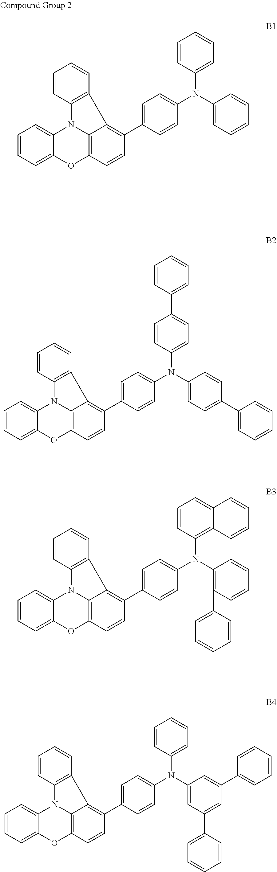


Applications Claiming Priority (2)
| Application Number | Priority Date | Filing Date | Title |
|---|---|---|---|
| KR10-2019-0133147 | 2019-10-24 | ||
| KR1020190133147A KR102890850B1 (en) | 2019-10-24 | 2019-10-24 | Organic electroluminescence device and polycyclic compound for organic electroluminescence device |
Publications (2)
| Publication Number | Publication Date |
|---|---|
| US20210126199A1 US20210126199A1 (en) | 2021-04-29 |
| US12295257B2 true US12295257B2 (en) | 2025-05-06 |
Family
ID=75586235
Family Applications (1)
| Application Number | Title | Priority Date | Filing Date |
|---|---|---|---|
| US17/010,424 Active 2043-01-05 US12295257B2 (en) | 2019-10-24 | 2020-09-02 | Organic electroluminescence device and polycyclic compound for same |
Country Status (2)
| Country | Link |
|---|---|
| US (1) | US12295257B2 (en) |
| KR (1) | KR102890850B1 (en) |
Families Citing this family (1)
| Publication number | Priority date | Publication date | Assignee | Title |
|---|---|---|---|---|
| EP4587441A1 (en) * | 2022-09-15 | 2025-07-23 | Merck Patent GmbH | Method for producing materials for use in electronic devices |
Citations (24)
| Publication number | Priority date | Publication date | Assignee | Title |
|---|---|---|---|---|
| WO2010050778A1 (en) | 2008-10-31 | 2010-05-06 | Gracel Display Inc. | Novel compounds for organic electronic material and organic electronic device using the same |
| WO2011088877A1 (en) | 2010-01-25 | 2011-07-28 | Merck Patent Gmbh | Compounds for electronic devices |
| WO2012077582A1 (en) | 2010-12-10 | 2012-06-14 | Canon Kabushiki Kaisha | Indolophenoxazine compound and organic light emitting device using the same |
| US20140027747A1 (en) * | 2011-04-01 | 2014-01-30 | Duksan High Metal Co., Ltd. | Compound, organic electronic element using same, and electronic device using the latter |
| US9012599B2 (en) | 2009-11-18 | 2015-04-21 | Merck Patent Gmbh | Nitrogen-containing condensed heterocyclic compounds for OLEDs |
| US9093650B2 (en) | 2013-08-02 | 2015-07-28 | Samsung Display Co., Ltd. | Organic light-emitting device |
| KR101546215B1 (en) | 2013-04-24 | 2015-08-20 | 롬엔드하스전자재료코리아유한회사 | Novel compounds for organic electronic material and organic electronic device using the same |
| JP5782836B2 (en) | 2011-05-27 | 2015-09-24 | コニカミノルタ株式会社 | ORGANIC ELECTROLUMINESCENT ELEMENT MATERIAL, ORGANIC ELECTROLUMINESCENT ELEMENT, DISPLAY DEVICE, LIGHTING DEVICE, AND COMPOUND |
| KR20150130797A (en) | 2014-05-14 | 2015-11-24 | 에스에프씨 주식회사 | An electroluminescent compound and an electroluminescent device comprising the same |
| KR20160006472A (en) | 2014-07-09 | 2016-01-19 | 삼성에스디아이 주식회사 | Compound, organic optoelectric device and display device |
| US20160079542A1 (en) * | 2014-09-09 | 2016-03-17 | Samsung Display Co., Ltd. | Organic electroluminescence device |
| JP6009816B2 (en) | 2012-05-22 | 2016-10-19 | ユー・ディー・シー アイルランド リミテッド | Charge transport material, organic electroluminescent element, light emitting device, display device and lighting device |
| US20170018600A1 (en) | 2015-07-13 | 2017-01-19 | Samsung Display Co., Ltd. | Organic light-emitting display device |
| US20170054083A1 (en) | 2015-08-21 | 2017-02-23 | Samsung Display Co., Ltd. | Organic light-emitting device |
| WO2017099326A1 (en) | 2015-12-08 | 2017-06-15 | 삼성에스디아이 주식회사 | Compound for organic optoelectronic device, organic optoelectronic device, and display apparatus |
| US20170183360A1 (en) * | 2015-12-28 | 2017-06-29 | Samsung Electronics Co., Ltd. | Bicarbazole compound, material for organic light-emitting device including bicarbazole compound, and organic light-emitting device including bicarbazole compound |
| US20170200899A1 (en) | 2016-01-13 | 2017-07-13 | Samsung Display Co., Ltd. | Organic light-emitting device |
| KR20170116974A (en) | 2016-04-12 | 2017-10-20 | 주식회사 엘지화학 | Hetero-cyclic compound and organic light emitting device comprising the same |
| KR20170139350A (en) | 2016-06-09 | 2017-12-19 | 주식회사 엘지화학 | Heterocyclic compound and organic light emitting device comprising the same |
| WO2018197447A1 (en) | 2017-04-25 | 2018-11-01 | Merck Patent Gmbh | Compounds for electronic devices |
| US10326111B2 (en) | 2015-04-16 | 2019-06-18 | Samsung Display Co., Ltd. | Organic light-emitting display apparatus and method of manufacturing the same |
| CN111704624A (en) | 2020-07-02 | 2020-09-25 | 苏州大学 | Indolo[3,2,1-kl]phenoxazine compound, preparation method and application thereof, and electronic device |
| KR20200136713A (en) | 2019-05-28 | 2020-12-08 | 주식회사 엘지화학 | Novel compound and organic light emitting device comprising the same |
| US20220199912A1 (en) * | 2020-12-15 | 2022-06-23 | Samsung Display Co., Ltd. | Light emitting device and polycyclic compound for the same |
-
2019
- 2019-10-24 KR KR1020190133147A patent/KR102890850B1/en active Active
-
2020
- 2020-09-02 US US17/010,424 patent/US12295257B2/en active Active
Patent Citations (39)
| Publication number | Priority date | Publication date | Assignee | Title |
|---|---|---|---|---|
| WO2010050778A1 (en) | 2008-10-31 | 2010-05-06 | Gracel Display Inc. | Novel compounds for organic electronic material and organic electronic device using the same |
| US9012599B2 (en) | 2009-11-18 | 2015-04-21 | Merck Patent Gmbh | Nitrogen-containing condensed heterocyclic compounds for OLEDs |
| KR101781235B1 (en) | 2009-11-18 | 2017-09-22 | 메르크 파텐트 게엠베하 | Nitrogen-containing condensed heterocyclic compounds for oleds |
| WO2011088877A1 (en) | 2010-01-25 | 2011-07-28 | Merck Patent Gmbh | Compounds for electronic devices |
| US20120292576A1 (en) * | 2010-01-25 | 2012-11-22 | Merck Patent Gmbh | Compounds for electronic devices |
| US9708262B2 (en) | 2010-01-25 | 2017-07-18 | Merck Patent Gmbh | Compounds for electronic devices |
| US9133119B2 (en) | 2010-01-25 | 2015-09-15 | Merck Patent Gmbh | Compounds for electronic devices |
| WO2012077582A1 (en) | 2010-12-10 | 2012-06-14 | Canon Kabushiki Kaisha | Indolophenoxazine compound and organic light emitting device using the same |
| US20130228770A1 (en) * | 2010-12-10 | 2013-09-05 | Canon Kabushiki Kaisha | Indolophenoxazine compound and organic light emitting device using the same |
| US9515270B2 (en) | 2010-12-10 | 2016-12-06 | Canon Kabushiki Kaisha | Indolophenoxazine compound and organic light emitting device using the same |
| US20140027747A1 (en) * | 2011-04-01 | 2014-01-30 | Duksan High Metal Co., Ltd. | Compound, organic electronic element using same, and electronic device using the latter |
| JP5782836B2 (en) | 2011-05-27 | 2015-09-24 | コニカミノルタ株式会社 | ORGANIC ELECTROLUMINESCENT ELEMENT MATERIAL, ORGANIC ELECTROLUMINESCENT ELEMENT, DISPLAY DEVICE, LIGHTING DEVICE, AND COMPOUND |
| US10283718B2 (en) | 2012-05-22 | 2019-05-07 | Udc Ireland Limited | Charge transporting material, organic electroluminescent element, light emitting device, display device and illumination device |
| JP6009816B2 (en) | 2012-05-22 | 2016-10-19 | ユー・ディー・シー アイルランド リミテッド | Charge transport material, organic electroluminescent element, light emitting device, display device and lighting device |
| KR101546215B1 (en) | 2013-04-24 | 2015-08-20 | 롬엔드하스전자재료코리아유한회사 | Novel compounds for organic electronic material and organic electronic device using the same |
| US9093650B2 (en) | 2013-08-02 | 2015-07-28 | Samsung Display Co., Ltd. | Organic light-emitting device |
| KR20150130797A (en) | 2014-05-14 | 2015-11-24 | 에스에프씨 주식회사 | An electroluminescent compound and an electroluminescent device comprising the same |
| US20170077416A1 (en) | 2014-07-09 | 2017-03-16 | Samsung Sdi Co., Ltd. | Compound, organic optoelectronic diode comprising same, and display |
| KR20160006472A (en) | 2014-07-09 | 2016-01-19 | 삼성에스디아이 주식회사 | Compound, organic optoelectric device and display device |
| US20160079542A1 (en) * | 2014-09-09 | 2016-03-17 | Samsung Display Co., Ltd. | Organic electroluminescence device |
| US10326111B2 (en) | 2015-04-16 | 2019-06-18 | Samsung Display Co., Ltd. | Organic light-emitting display apparatus and method of manufacturing the same |
| US20170018600A1 (en) | 2015-07-13 | 2017-01-19 | Samsung Display Co., Ltd. | Organic light-emitting display device |
| US10797246B2 (en) | 2015-08-21 | 2020-10-06 | Samsung Display Co., Ltd. | Organic light-emitting device |
| KR101796227B1 (en) | 2015-08-21 | 2017-11-10 | 삼성디스플레이 주식회사 | Organic light-emitting device |
| US20170054083A1 (en) | 2015-08-21 | 2017-02-23 | Samsung Display Co., Ltd. | Organic light-emitting device |
| WO2017099326A1 (en) | 2015-12-08 | 2017-06-15 | 삼성에스디아이 주식회사 | Compound for organic optoelectronic device, organic optoelectronic device, and display apparatus |
| KR101962420B1 (en) | 2015-12-08 | 2019-03-26 | 삼성에스디아이 주식회사 | Organic compound for optoelectronic device and organic optoelectronic device and display device |
| US20170183360A1 (en) * | 2015-12-28 | 2017-06-29 | Samsung Electronics Co., Ltd. | Bicarbazole compound, material for organic light-emitting device including bicarbazole compound, and organic light-emitting device including bicarbazole compound |
| US10336772B2 (en) | 2015-12-28 | 2019-07-02 | Samsung Electronics Co., Ltd. | Bicarbazole compound, material for organic light-emitting device including bicarbazole compound, and organic light-emitting device including bicarbazole compound |
| US20170200899A1 (en) | 2016-01-13 | 2017-07-13 | Samsung Display Co., Ltd. | Organic light-emitting device |
| KR101936221B1 (en) | 2016-04-12 | 2019-01-08 | 주식회사 엘지화학 | Hetero-cyclic compound and organic light emitting device comprising the same |
| KR20170116974A (en) | 2016-04-12 | 2017-10-20 | 주식회사 엘지화학 | Hetero-cyclic compound and organic light emitting device comprising the same |
| KR20170139350A (en) | 2016-06-09 | 2017-12-19 | 주식회사 엘지화학 | Heterocyclic compound and organic light emitting device comprising the same |
| WO2018197447A1 (en) | 2017-04-25 | 2018-11-01 | Merck Patent Gmbh | Compounds for electronic devices |
| KR20190141220A (en) | 2017-04-25 | 2019-12-23 | 메르크 파텐트 게엠베하 | Compound for electronic device |
| US20200199154A1 (en) | 2017-04-25 | 2020-06-25 | Merck Patent Gmbh | Compounds for electronic devices |
| KR20200136713A (en) | 2019-05-28 | 2020-12-08 | 주식회사 엘지화학 | Novel compound and organic light emitting device comprising the same |
| CN111704624A (en) | 2020-07-02 | 2020-09-25 | 苏州大学 | Indolo[3,2,1-kl]phenoxazine compound, preparation method and application thereof, and electronic device |
| US20220199912A1 (en) * | 2020-12-15 | 2022-06-23 | Samsung Display Co., Ltd. | Light emitting device and polycyclic compound for the same |
Non-Patent Citations (4)
| Title |
|---|
| English translation of JP 2012/248663A, and the original JP 2012/248663A, Mayuka Hikime, Dec. 13, 2012 (Year: 2012). * |
| English translation of WO 2013/183851 A1, and the original WO 2013/183851 A1, Seo-Yong Hyun, Dec. 12, 2013 (Year: 2013). * |
| Google_Translation_of_CN_111704624 (Year: 2024). |
| U.S. Office Action dated Aug. 28, 2024, issued in U.S. Appl. No. 17/486,049 (12 pages). |
Also Published As
| Publication number | Publication date |
|---|---|
| US20210126199A1 (en) | 2021-04-29 |
| KR102890850B1 (en) | 2025-11-27 |
| KR20210049240A (en) | 2021-05-06 |
Similar Documents
| Publication | Publication Date | Title |
|---|---|---|
| EP3909946B1 (en) | Organic electroluminescence device and polycyclic compound for organic electroluminescence device | |
| US11121329B2 (en) | Amine compound and organic electroluminescence device including the same | |
| US11230521B2 (en) | Monoamine compound and organic electroluminescence device including the same | |
| US20210119135A1 (en) | Luminescence device and amine compound for luminescence device | |
| US20210202861A1 (en) | Organic electroluminescence device and polycyclic compound for organic electroluminescence device | |
| US20230127951A1 (en) | Organic electroluminescence device and polycyclic compound for organic electroluminescence device | |
| US11980091B2 (en) | Organic electroluminescence device and compound for organic electroluminescence device | |
| US11335860B2 (en) | Organic electroluminescence device and condensed cyclic compound for organic electroluminescence device | |
| US12114564B2 (en) | Nitrogen-containing compound for organic electroluminescence device | |
| US11785837B2 (en) | Organic electroluminescence device and polycyclic compound for organic electroluminescence device | |
| US20210126197A1 (en) | Organic electroluminescence device and amine compound for organic electroluminescence device | |
| US12089489B2 (en) | Organic electroluminescence device and diamine compound for organic electroluminescence device | |
| US11849633B2 (en) | Organic electroluminescence device and monoamine compound for organic electroluminescence device | |
| EP3915980A2 (en) | Organic electroluminescence device and amine compound for organic electroluminescence device | |
| US12441699B2 (en) | Organic electroluminescence device and amine compound for organic electroluminescence device | |
| US20210126195A1 (en) | Organic electroluminescence device and polycyclic compound for organic electroluminescence device | |
| US12295257B2 (en) | Organic electroluminescence device and polycyclic compound for same | |
| US11980088B2 (en) | Organic electroluminescence device and amine compound for organic electroluminescence device | |
| KR102779138B1 (en) | Organic electroluminescence device and monoamine compound for organic electroluminescence device | |
| US12446464B2 (en) | Organic electroluminescence device and polycyclic compound for organic electroluminescence device | |
| US11770973B2 (en) | Organic electroluminescence device and amine compound for organic electroluminescence device | |
| US20210305509A1 (en) | Organic electroluminescence device and amine compound for organic electroluminescence device |
Legal Events
| Date | Code | Title | Description |
|---|---|---|---|
| AS | Assignment |
Owner name: SAMSUNG DISPLAY CO., LTD., KOREA, REPUBLIC OF Free format text: ASSIGNMENT OF ASSIGNORS INTEREST;ASSIGNOR:UNO, TAKUYA;REEL/FRAME:053676/0722 Effective date: 20200604 |
|
| FEPP | Fee payment procedure |
Free format text: ENTITY STATUS SET TO UNDISCOUNTED (ORIGINAL EVENT CODE: BIG.); ENTITY STATUS OF PATENT OWNER: LARGE ENTITY |
|
| STPP | Information on status: patent application and granting procedure in general |
Free format text: APPLICATION DISPATCHED FROM PREEXAM, NOT YET DOCKETED |
|
| STPP | Information on status: patent application and granting procedure in general |
Free format text: DOCKETED NEW CASE - READY FOR EXAMINATION |
|
| STPP | Information on status: patent application and granting procedure in general |
Free format text: NON FINAL ACTION MAILED |
|
| STPP | Information on status: patent application and granting procedure in general |
Free format text: RESPONSE TO NON-FINAL OFFICE ACTION ENTERED AND FORWARDED TO EXAMINER |
|
| STPP | Information on status: patent application and granting procedure in general |
Free format text: FINAL REJECTION MAILED |
|
| STPP | Information on status: patent application and granting procedure in general |
Free format text: RESPONSE AFTER FINAL ACTION FORWARDED TO EXAMINER |
|
| STPP | Information on status: patent application and granting procedure in general |
Free format text: ADVISORY ACTION MAILED |
|
| STPP | Information on status: patent application and granting procedure in general |
Free format text: DOCKETED NEW CASE - READY FOR EXAMINATION |
|
| STPP | Information on status: patent application and granting procedure in general |
Free format text: NON FINAL ACTION MAILED |
|
| STPP | Information on status: patent application and granting procedure in general |
Free format text: RESPONSE TO NON-FINAL OFFICE ACTION ENTERED AND FORWARDED TO EXAMINER |
|
| STPP | Information on status: patent application and granting procedure in general |
Free format text: AWAITING TC RESP., ISSUE FEE NOT PAID |
|
| STPP | Information on status: patent application and granting procedure in general |
Free format text: NOTICE OF ALLOWANCE MAILED -- APPLICATION RECEIVED IN OFFICE OF PUBLICATIONS |
|
| STPP | Information on status: patent application and granting procedure in general |
Free format text: PUBLICATIONS -- ISSUE FEE PAYMENT VERIFIED |
|
| STCF | Information on status: patent grant |
Free format text: PATENTED CASE |