US12280801B2 - Method for obstacle-avoidance in self-driving, system, and storage medium - Google Patents
Method for obstacle-avoidance in self-driving, system, and storage medium Download PDFInfo
- Publication number
- US12280801B2 US12280801B2 US18/013,064 US202218013064A US12280801B2 US 12280801 B2 US12280801 B2 US 12280801B2 US 202218013064 A US202218013064 A US 202218013064A US 12280801 B2 US12280801 B2 US 12280801B2
- Authority
- US
- United States
- Prior art keywords
- force
- point
- obstacles
- feasible
- determining
- Prior art date
- Legal status (The legal status is an assumption and is not a legal conclusion. Google has not performed a legal analysis and makes no representation as to the accuracy of the status listed.)
- Active, expires
Links
Images


Classifications
-
- B—PERFORMING OPERATIONS; TRANSPORTING
- B62—LAND VEHICLES FOR TRAVELLING OTHERWISE THAN ON RAILS
- B62D—MOTOR VEHICLES; TRAILERS
- B62D15/00—Steering not otherwise provided for
- B62D15/02—Steering position indicators ; Steering position determination; Steering aids
- B62D15/025—Active steering aids, e.g. helping the driver by actively influencing the steering system after environment evaluation
- B62D15/0265—Automatic obstacle avoidance by steering
-
- B—PERFORMING OPERATIONS; TRANSPORTING
- B60—VEHICLES IN GENERAL
- B60W—CONJOINT CONTROL OF VEHICLE SUB-UNITS OF DIFFERENT TYPE OR DIFFERENT FUNCTION; CONTROL SYSTEMS SPECIALLY ADAPTED FOR HYBRID VEHICLES; ROAD VEHICLE DRIVE CONTROL SYSTEMS FOR PURPOSES NOT RELATED TO THE CONTROL OF A PARTICULAR SUB-UNIT
- B60W60/00—Drive control systems specially adapted for autonomous road vehicles
- B60W60/001—Planning or execution of driving tasks
- B60W60/0011—Planning or execution of driving tasks involving control alternatives for a single driving scenario, e.g. planning several paths to avoid obstacles
-
- B—PERFORMING OPERATIONS; TRANSPORTING
- B60—VEHICLES IN GENERAL
- B60W—CONJOINT CONTROL OF VEHICLE SUB-UNITS OF DIFFERENT TYPE OR DIFFERENT FUNCTION; CONTROL SYSTEMS SPECIALLY ADAPTED FOR HYBRID VEHICLES; ROAD VEHICLE DRIVE CONTROL SYSTEMS FOR PURPOSES NOT RELATED TO THE CONTROL OF A PARTICULAR SUB-UNIT
- B60W30/00—Purposes of road vehicle drive control systems not related to the control of a particular sub-unit, e.g. of systems using conjoint control of vehicle sub-units
- B60W30/08—Active safety systems predicting or avoiding probable or impending collision or attempting to minimise its consequences
- B60W30/09—Taking automatic action to avoid collision, e.g. braking and steering
-
- B—PERFORMING OPERATIONS; TRANSPORTING
- B60—VEHICLES IN GENERAL
- B60W—CONJOINT CONTROL OF VEHICLE SUB-UNITS OF DIFFERENT TYPE OR DIFFERENT FUNCTION; CONTROL SYSTEMS SPECIALLY ADAPTED FOR HYBRID VEHICLES; ROAD VEHICLE DRIVE CONTROL SYSTEMS FOR PURPOSES NOT RELATED TO THE CONTROL OF A PARTICULAR SUB-UNIT
- B60W40/00—Estimation or calculation of non-directly measurable driving parameters for road vehicle drive control systems not related to the control of a particular sub unit, e.g. by using mathematical models
- B60W40/02—Estimation or calculation of non-directly measurable driving parameters for road vehicle drive control systems not related to the control of a particular sub unit, e.g. by using mathematical models related to ambient conditions
- B60W40/06—Road conditions
- B60W40/072—Curvature of the road
-
- B—PERFORMING OPERATIONS; TRANSPORTING
- B60—VEHICLES IN GENERAL
- B60W—CONJOINT CONTROL OF VEHICLE SUB-UNITS OF DIFFERENT TYPE OR DIFFERENT FUNCTION; CONTROL SYSTEMS SPECIALLY ADAPTED FOR HYBRID VEHICLES; ROAD VEHICLE DRIVE CONTROL SYSTEMS FOR PURPOSES NOT RELATED TO THE CONTROL OF A PARTICULAR SUB-UNIT
- B60W60/00—Drive control systems specially adapted for autonomous road vehicles
- B60W60/001—Planning or execution of driving tasks
- B60W60/0015—Planning or execution of driving tasks specially adapted for safety
-
- B—PERFORMING OPERATIONS; TRANSPORTING
- B62—LAND VEHICLES FOR TRAVELLING OTHERWISE THAN ON RAILS
- B62D—MOTOR VEHICLES; TRAILERS
- B62D15/00—Steering not otherwise provided for
- B62D15/02—Steering position indicators ; Steering position determination; Steering aids
- B62D15/021—Determination of steering angle
-
- G—PHYSICS
- G01—MEASURING; TESTING
- G01C—MEASURING DISTANCES, LEVELS OR BEARINGS; SURVEYING; NAVIGATION; GYROSCOPIC INSTRUMENTS; PHOTOGRAMMETRY OR VIDEOGRAMMETRY
- G01C21/00—Navigation; Navigational instruments not provided for in groups G01C1/00 - G01C19/00
- G01C21/20—Instruments for performing navigational calculations
-
- G—PHYSICS
- G05—CONTROLLING; REGULATING
- G05D—SYSTEMS FOR CONTROLLING OR REGULATING NON-ELECTRIC VARIABLES
- G05D1/00—Control of position, course, altitude or attitude of land, water, air or space vehicles, e.g. using automatic pilots
- G05D1/02—Control of position or course in two dimensions
-
- B—PERFORMING OPERATIONS; TRANSPORTING
- B60—VEHICLES IN GENERAL
- B60W—CONJOINT CONTROL OF VEHICLE SUB-UNITS OF DIFFERENT TYPE OR DIFFERENT FUNCTION; CONTROL SYSTEMS SPECIALLY ADAPTED FOR HYBRID VEHICLES; ROAD VEHICLE DRIVE CONTROL SYSTEMS FOR PURPOSES NOT RELATED TO THE CONTROL OF A PARTICULAR SUB-UNIT
- B60W2552/00—Input parameters relating to infrastructure
- B60W2552/50—Barriers
-
- B—PERFORMING OPERATIONS; TRANSPORTING
- B60—VEHICLES IN GENERAL
- B60W—CONJOINT CONTROL OF VEHICLE SUB-UNITS OF DIFFERENT TYPE OR DIFFERENT FUNCTION; CONTROL SYSTEMS SPECIALLY ADAPTED FOR HYBRID VEHICLES; ROAD VEHICLE DRIVE CONTROL SYSTEMS FOR PURPOSES NOT RELATED TO THE CONTROL OF A PARTICULAR SUB-UNIT
- B60W2554/00—Input parameters relating to objects
- B60W2554/40—Dynamic objects, e.g. animals, windblown objects
- B60W2554/404—Characteristics
- B60W2554/4049—Relationship among other objects, e.g. converging dynamic objects
-
- B—PERFORMING OPERATIONS; TRANSPORTING
- B60—VEHICLES IN GENERAL
- B60W—CONJOINT CONTROL OF VEHICLE SUB-UNITS OF DIFFERENT TYPE OR DIFFERENT FUNCTION; CONTROL SYSTEMS SPECIALLY ADAPTED FOR HYBRID VEHICLES; ROAD VEHICLE DRIVE CONTROL SYSTEMS FOR PURPOSES NOT RELATED TO THE CONTROL OF A PARTICULAR SUB-UNIT
- B60W2710/00—Output or target parameters relating to a particular sub-units
- B60W2710/20—Steering systems
- B60W2710/207—Steering angle of wheels
-
- B—PERFORMING OPERATIONS; TRANSPORTING
- B60—VEHICLES IN GENERAL
- B60W—CONJOINT CONTROL OF VEHICLE SUB-UNITS OF DIFFERENT TYPE OR DIFFERENT FUNCTION; CONTROL SYSTEMS SPECIALLY ADAPTED FOR HYBRID VEHICLES; ROAD VEHICLE DRIVE CONTROL SYSTEMS FOR PURPOSES NOT RELATED TO THE CONTROL OF A PARTICULAR SUB-UNIT
- B60W30/00—Purposes of road vehicle drive control systems not related to the control of a particular sub-unit, e.g. of systems using conjoint control of vehicle sub-units
- B60W30/08—Active safety systems predicting or avoiding probable or impending collision or attempting to minimise its consequences
- B60W30/095—Predicting travel path or likelihood of collision
- B60W30/0956—Predicting travel path or likelihood of collision the prediction being responsive to traffic or environmental parameters
Definitions
- the subject matter herein generally relates to vehicle technology, and particularly to a method for obstacle-avoidance in self-driving, a system, and a computer readable storage medium.
- the present application is aim to provide a method for self-driving obstacle avoidance, a system, and a computer readable storage medium, which are to resolve a defect of Artificial Potential Field getting into the local minimum, and a problem of the environmental constraints of the self-driving vehicle and the constraints of the vehicle itself in a structured urban environment.
- a first aspect of the present application provides a method for obstacle-avoidance in self-driving comprising:
- the determining of the feasible area according to the information of the obstacles includes:
- the determining one or more feasible areas according to the visual borders of the one or more obstacles, the point O of the center of the body of the instant vehicle, and the minimum turn radius of the instant vehicle includes:
- the obtaining of safety factors of the one or more feasible areas according to borders of the feasible areas and a relative position between each obstacle and the instant vehicle includes:
- the obtaining of the deviation between the direction of each feasible area and the current heading of the body of the vehicle and the deviation between the direction of each feasible area and the direction of the corresponding waypoint includes:
- the determining of the attractive force of the waypoint to the instant vehicle according to the waypoint and the preset attractive potential field function includes:
- a second aspect of the present application provides a system for obstacle-avoidance in self-driving, comprising:
- a third aspect of the present application provides a computer readable storage medium where computer executable instructions are stored herein, the computer executable instructions are used for executing the steps of method for obstacle-avoidance in self-driving of the first aspect when the computer executable instructions are executed by at least one processor.
- the disclosure determines the feasible area according to the information of the obstacles in the direction of travel of the self-driving vehicle on the road, and determines a waypoint according to the feasible area, and establishes the attractive potential field function according to the waypoint.
- the disclosure further establishes the repulsive potential field function according to the obstacles on sides of the feasible area, thus a new artificial potential field model is provided.
- the artificial potential field model well reflects the strength of the potential field of a virtual potential field to a self-driving vehicle under environmental constraints.
- the defect of the artificial potential field deflecting into the local minimum and the problem of the environmental constraints of the self-driving vehicle and the constraints of the vehicle itself in a structured urban environment can be resolved, thus adaptability to environments and a reliability of the obstacle avoidance in self-driving is improved.
- FIG. 1 is a flowchart of a method for obstacle-avoidance in self-driving according to the present disclosure.
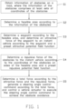
- FIG. 2 is a view of visual borders of obstacles according to the present disclosure.
- FIG. 3 is a view of obstacle constraints according to the present disclosure.
- FIG. 4 is a structural diagram of a system for obstacle-avoidance in self-driving according to the present disclosure.
- An embodiment of the application provides a method for self-driving obstacle avoidance, which is adaptable for a self-driving vehicle and can accomplish obstacle avoidance in a self-driving system of a self-driving vehicle.
- the method of the embodiment of the instant application includes steps S 1 ⁇ S 6 as follows:
- the self-driving vehicle is equipped with sensor for sensing obstacles, and the sensor for sensing obstacles can detect the information of the obstacles on the road ahead in real time when the self-driving vehicle is moving on the road.
- the other objects on the road and influencing a driving of the self-driving vehicle can be considered as the obstacles, for example, vehicles, pedestrians, or the like.
- the information of the obstacles is sensed by the sensor and is output as original data which is a series of sets of coordinates of borders of obstacles.
- determining which of one or more areas on the road ahead are the feasible areas is carried out according to the information of the obstacles.
- the determining manner of the feasible areas can be various, and the embodiments is not limited herein.
- Step S 3 determining a waypoint according to the feasible area, and determining an attractive force of the waypoint to the instant vehicle according to the waypoint and a preset attractive potential field function;
- the waypoint for the self-driving vehicle can dynamically determined.
- the waypoint can be understood as a forward target point of the self-driving vehicle, namely, a position point that the self-driving vehicle will arrive at in the future during the self-driving, the vehicle being expected to pass through the feasible area.
- the waypoint is a point guiding a driving of the self-driving vehicle, namely, the waypoint and the self-driving vehicle can attract each other in the artificial field, attracting the self-driving vehicle to the waypoint.
- the waypoint should be a position point in the feasible area.
- the waypoint can be determined according to the feasible area.
- the waypoint is a point selected from the center line of the road.
- the center line of the road and a selection of the waypoint is known to those of ordinary skill in self-driving art, which will not be repeated here.
- the disclosure aims to determine the attractive force of the attractive potential field by using the waypoint.
- Step S 4 determining a repulsive force of the obstacles to the instant vehicle according to the coordinates of the obstacles on sides of the feasible area and a preset repulsive potential field function;
- the method of the embodiment determines the feasible area according to the information of the obstacles on a road forward of the self-driving vehicle, and determines a waypoint according to the feasible area, and establishes the attractive potential field function according to the waypoint.
- the disclosure further establishes the repulsive potential field function according to the obstacles on sides of the feasible area, thus a new artificial potential field model is provided.
- the artificial potential field model well reflects the strength of the potential field of a virtual potential field to a self-driving vehicle having the environmental constraints.
- the defect of the artificial potential field getting into the local minimum and the problem of the environmental constraints of the self-driving vehicle and the constraints of the vehicle itself under a structured urban environment can be resolved, thus an adaptability to environments and a reliability of the obstacle-avoidance in self-driving can be improved.
- the step S 2 includes steps S 21 ⁇ S 24 :
- Step S 21 determining visual borders of one or more obstacles according to the information of the obstacles, each obstacle including one or more visual borders.
- a series of sets of coordinates of the visual borders of the obstacles can be obtained via the sensor.
- a definition is given to the visual borders of each obstacle: supposing that the obstacle is a polygon, it represents the obstacle's number and the obstacle has many vertices, and for the obstacle being an ellipse or a circle in sharp, the obstacle can be formed by an inscribed regular polygon of the ellipse or the circle.
- the information of the obstacles is obtained via taking the sensor as the coordinate origin and performing a coordinate transformation based on an installation position of the sensor on the vehicle, namely the information of the visual borders of the obstacles in a vehicle coordinate system.
- N line segments are obtained, and a second polygon encompassing all the line segments but excluding the obstacle itself is obtained.
- One or more edges in all of the edges of the second polygon which are the edges of the obstacle are determined, namely the borders of a corresponding visual obstacle are obtained.
- four vertices of the obstacle O 1 , and four vertices of the obstacle O 2 are connected with the origin O to respectively obtain four line segments.
- the second polygon which encompasses all corresponding line segments but excludes the obstacle is O-A 1 -D 1
- the second obstacle O 2 is O-B 2 -A 2 -D 2 .
- the visual border of the obstacle O 1 is A 1 -D 1
- the visual borders of the obstacle O 2 is A 2 -B 2 and A 2 -D 2 .
- Step S 22 determining one or more feasible areas according to the visual borders of the one or more obstacles, a point O of the center of the body of the instant vehicle, and a minimum turn radius of the instant vehicle.
- step S 22 can include:
- a point F and a point E in the obstacle O 1 are the left boundary point of the obstacle O 1 and the right boundary point of the obstacle O 1 , thus an arc OF and an arc OE are obtained, and an area between the arc OF and the arc OE can be determined to be infeasible areas.
- a point J and a point H in the obstacle O 2 are the left boundary point of the obstacle O 2 and the right boundary point of the obstacle O 2 , thus an arc OJ and an arc OH are obtained, and an area between the arc OJ and the arc OH can be determined to be infeasible areas.
- a principle of generating two arcs which are tangent to the heading of the instant vehicle are as follow: drawing an envelope curve of the arc to each obstacle by taking the point of the center of the body of the self-driving vehicle, the left boundary point of the obstacle, and the right boundary point of the obstacle as the points of the arc.
- the arc is tangent to the heading of the instant vehicle.
- O x , O y are sets of coordinates of the left boundary point of the obstacle or the right boundary point of the obstacle in the vehicle coordinate system at a time t
- the corresponding radius of the arc can be determined according to following formula:
- the infeasible areas of the obstacle i are always formed by two arcs O Li and O Ri which are tangent to the heading of the vehicle, where O Li is a left arc curve segment of the obstacle i, and O Ri is a right arc curve segment of the obstacle i.
- O Li and O Ri in the equation are:
- Two turn radius arcs are generated according to the point O and the minimum turn radius R min of the instant vehicle, for example two turn radius arcs at a left side and a right side of the point O. Whether or not a residual area excluding the infeasible area is the feasible area is determined according to the two turn radius arcs, thus one or more feasible areas can be determined; where boundaries of each feasible area includes a left arc and a right arc;
- the minimum turn radius of the self-driving vehicle is a constraint of the vehicle itself.
- the minimum turn radius refers to a radius of a track circle that a center of an outer steering wheel rolls on a support plane when a steering wheel turns to a limit position and the self-driving vehicle turns at the lowest stable speed.
- the minimum turn radius largely characterizes an ability that the self-driving vehicle can pass through a narrow tortuous region or navigate around the non-traversable objects. The less the turning radius, the better are the maneuvering characteristics of the self-driving vehicle.
- the area where the self-driving vehicle cannot be arrived is the infeasible area of the self-driving vehicle.
- the area excluding the infeasible area are all the feasible areas.
- a number of obstacles exist on the road, and a number of feasible areas spaced apart by the infeasible areas via the operations in the aforementioned steps are established.
- Step S 23 obtaining safety factors of the one or more feasible areas according to borders of the feasible areas and a relative position between each obstacle and the instant vehicle, and obtaining a deviation between a direction of each feasible area and a current heading of the body of the vehicle and a deviation between the direction of each feasible area and a direction of a corresponding waypoint according to the borders of the feasible areas.
- the safety S safety of each feasible area is therefore considered.
- W i is a width factor of the ith feasible area, representing a width of the feasible area
- D i is an obstacle factor of the ith feasible area, representing a position which is influenced by the obstacle.
- the step S 23 includes steps S 231 ⁇ S 233 :
- Step S 231 using the point O as a center of a circle and the preset radius to generate a reference arc, and determining a width factor of each feasible area according to a length of an arc between a point B and a point C and a length of an arc between a point A and a point D, where the point B and the point C are the points where the reference arc intersects with the left arc and the right arc, and the point A and the point D are points where the reference arc intersects with the two turn radius arcs.
- the origin of the vehicle coordinate system as a center of the circle and any fixed radius to generate the arc are used.
- the arc intersects with the boundary arcs of the feasible areas at the point B and the point C, and intersects with the minimum turn radius arc of the self-driving vehicle at the point A and the point D.
- W i /
- Step S 232 determining a point I of one obstacle closest to the instant vehicle from the points of the obstacles at sides of the feasible areas, and determining a factor of each obstacle according to a length of a straight line between the pint O and the pint I, a length of a straight line between the point B and the point C, a length of a straight line between the point O and the point C, and a width of the instant vehicle.
- W car is a width of the vehicle
- OI, BC, and OC are each a length of a straight line segment between two points.
- Step S 233 determining a safety factor of each feasible area according to the width factor of each feasible area and the factor of each obstacle.
- S safety f(W i ,D i ) an expression for expressing a relationship of the safety, the safety factor, the width factor, and the obstacle factor.
- the calculating formula can be a manner of a weighted sum calculation.
- the weights of the width factor and the obstacle factor can be adjusted according to an actual technology requirement.
- a size of the determined width factor can be also adjusted.
- it can be suitable adjusted according to the actual needs.
- a selection of the feasible area should further consider the following two aspects, a comfort-related deviation between each feasible area and a current heading of the body of the vehicle, and an operation efficiency related deviation between each feasible area and a direction of a corresponding waypoint.
- the obtaining of the deviation between the direction of each feasible area and the current heading of the body of the vehicle and the deviation between the direction of each feasible area and the direction of the corresponding waypoint according to the borders of the feasible areas includes:
- H deviation ( i ) min ⁇ ⁇ ⁇ " ⁇ [LeftBracketingBar]” 1 R L ⁇ i ⁇ " ⁇ [RightBracketingBar]” , ⁇ " ⁇ [LeftBracketingBar]” 1 R R ⁇ i ⁇ " ⁇ [RightBracketingBar]” ⁇ .
- G deviation ( i ) min ⁇ ⁇ ⁇ " ⁇ [LeftBracketingBar]” ( 1 R g - 1 R L ⁇ i ) ⁇ " ⁇ [RightBracketingBar]” , ⁇ " ⁇ [LeftBracketingBar]” 1 R g - 1 R R ⁇ i ⁇ " ⁇ [RightBracketingBar]” ⁇ ;
- Step S 24 selecting one feasible area from the feasible areas to output as the feasible area which is optimal according to the safety factors, the deviation between the direction of each feasible area and the current heading of the body of the vehicle, and the deviation between the direction of each feasible area and the direction of the corresponding waypoint.
- k s , k h , k g are respectively a weight coefficient of a safe factor, a weight coefficient of a deviation factor of the heading, and a weight coefficient of a deviation factor of the target point.
- the weights can be set according to the biases of the three factors.
- One feasible area can be determined according to a determination of the cost function of the feasible areas. A minimum value of the cost function is the feasible area which is optimal. Simultaneously, a largest threshold of the cost function also needs to be set. If greater than the threshold, it illustrates that the cost is too high, and is infeasible.
- step S 3 incudes:
- the artificial field on the obstacle avoidance of the self-driving vehicle should meet four basic conditions. Firstly, it should be capable of avoiding the inherent defect of a conventional artificial field function. Secondly, the target point function of its potential field function is further required to reflect the dynamic target point of the self-driving vehicle. Thirdly, the potential field of the potential field function should be capable of reflecting strength of influence of the structured urban environment to the self-driving vehicle at each distance direction. Fourth, there is a certain mapping relationship between a certain variation and the dynamic constraints of the vehicle. However, some characters of a GAUSSIAN function satisfy the condition, thus an artificial field based on the GAUSSIAN function is established. In the embodiment, a preset attractive potential field function is shown as the following formula:
- (X, Y) is the sets of coordinates of the point of the center of the body of the instant vehicle in a global coordinate system
- (X g , Y g ) is the sets of coordinates of the waypoint in the global coordinate system
- k att is a gain coefficient of an attractive potential
- d attx is a longitudinal action distance of the force field on the instant vehicle
- d atty is a horizontal action distance of the attractive force field on the instant vehicle
- I g is a preset integer reflecting a boundary of the strength of the potential field.
- determining the waypoint according to the feasible area and determining the attractive force of the waypoint to the instant vehicle according to the waypoint and the preset attractive potential field function, is shown as the following formula in detail:
- G ⁇ is an unit vector pointing to an attractive point from the point O
- K att ′ is a gain coefficient of the attractive force
- step S 4 incudes:
- the obstacles can be detected via a sensing system, for example LIDAR.
- a sensing system for example LIDAR.
- a relative coordinate of one point of each obstacle which is closest to the vehicle namely a longitudinal closest point
- a relative coordinate of an extreme boundary point of each obstacle namely a lateral closest point
- a repulsive potential field and an influencing distance of a conventional repulsive potential field model at a boundary of each obstacle are always invariable, and the repulsive potential field of the conventional repulsive potential field model is sharply increased when coming closer to the corresponding obstacle.
- the influencing distance and the repulsive potential field of one obstacle to the self-driving vehicle are variable, and the influencing distance of the longitudinal repulsive potential field should be largely greater than the repulsive potential field exerted by the obstacle lateral to the self-driving vehicle in a forward direction of the self-driving vehicle.
- a variation of the repulsive potential field should be smooth. If it is too sharp, the vehicle actuator of the vehicle will be caused to be not capable of executing and a comfort of the vehicle will be influenced.
- the preset repulsive potential field of the embodiment can be expressed as the following formula:
- d repx (i) is a distance of a longitudinal action between the repulsive force field of the ith obstacle and the instant vehicle
- d repy (i) is a distance of a horizontal action between the repulsive force field of the ith obstacle and the instant vehicle
- I O is a preset integer
- (X, Y) is the sets of coordinates of the point of the center of the body of the instant vehicle in the global coordinate system
- k rep is a gain coefficient of the repulsion potential.
- determining a repulsive force of the obstacles to the instant vehicle according to the coordinates of the obstacles on sides of the feasible area and a preset repulsive potential field function is shown as the following formula in detail:
- ⁇ right arrow over (F) ⁇ rep (i) is the repulsive force of the repulsive force field of the ith obstacle to the instant vehicle
- k rep ′ 4*k rep *I O
- ⁇ right arrow over (a) ⁇ O is an unit vector pointing to the repulsive force point from O
- step S 5 includes:
- the direction of the total force decides a movement direction of the controlled object.
- the attractive force and the repulsive force are respectively divided into force components in two coordinate axes.
- the force components of the repulsive force in the abscissa axis and the ordinate axis are:
- i s is a transmission ratio of a steering system.
- another embodiment of the disclosure provides a system for self-driving obstacle avoidance, which is capable of achieving the method of the aforementioned embodiment.
- the system of the embodiment includes:
- the units of division is merely a logical function division and may be other division in actual implementation.
- the units described as separate parts may or may not be physically separate, and parts displayed as units may or may not be physical units, may be located in one position, or may be distributed on a plurality of network units. Some or all of the units may be selected according to actual needs to achieve the objectives of the solutions of the embodiments.
- the system of the aforementioned embodiment corresponds to the method of the aforementioned embodiment.
- certain parts not described in the system of the aforementioned embodiment can be obtained by referring to the content of the method of the aforementioned embodiment.
- the details of the steps recorded in the method of the aforementioned embodiment can be considered as the function that the system of the embodiment can achieve, and are not repeated redundantly herein.
- the integrated module/unit of the system for self-driving obstacle avoidance is implemented in the form of or by means of a software functional unit and is sold or used as an independent product, all parts of the integrated module/unit of the system for self-driving obstacle avoidance may be stored in a computer-readable storage medium.
- the embodiment of the present disclosure further provides a computer storage medium where computer executable instructions are stored herein, the computer executable instructions are used for executing the method for self-driving obstacle avoidance when the computer executable instructions being executed by at least one processor.
- the computer-readable storage medium may include any entity or device capable of recording and carrying the program codes, recording media, USB flash disk, mobile hard disk, disk, computer-readable storage medium, read-only memory, Random access memory, electrical carrier signals, telecommunications signals, software distribution package, and so on.
Landscapes
- Engineering & Computer Science (AREA)
- Mechanical Engineering (AREA)
- Transportation (AREA)
- Automation & Control Theory (AREA)
- Radar, Positioning & Navigation (AREA)
- Remote Sensing (AREA)
- Human Computer Interaction (AREA)
- Physics & Mathematics (AREA)
- Chemical & Material Sciences (AREA)
- Combustion & Propulsion (AREA)
- General Physics & Mathematics (AREA)
- Mathematical Physics (AREA)
- Aviation & Aerospace Engineering (AREA)
- Control Of Position, Course, Altitude, Or Attitude Of Moving Bodies (AREA)
- Traffic Control Systems (AREA)
Abstract
Description
-
- Obtaining information of the obstacles on the road, where the information of the obstacles includes at least sets of coordinates of the obstacles;
- Determining a feasible area according to the information of the obstacles;
- Determining a waypoint according to the feasible area, and determining an attractive force of the waypoint to an instant vehicle according to the waypoint and a preset attractive potential field function;
- Determining a repulsive force of the obstacles to the instant vehicle according to the coordinates of the obstacles on sides of the feasible area and a preset repulsive potential field function; and
- Determining a total force according to the attractive force and the repulsive force, generating a steering angle control command according to the total force, and controlling a vehicle actuator to execute the steering angle control command to achieve obstacle avoidance.
-
- Determining visual borders of one or more obstacles according to the information of the obstacles, each obstacle including one or more visual borders;
- Determining one or more feasible areas according to the visual borders of the one or more obstacles, a point O of a center of the body of the instant vehicle, and a minimum turn radius of the instant vehicle;
- Obtaining safety factors of the one or more feasible areas according to borders of the feasible areas and a relative position between each obstacle and the instant vehicle, and obtaining a deviation between a direction of each feasible area and a current heading of the body of the vehicle and a deviation between the direction of each feasible area and a direction of a corresponding waypoint according to the borders of the feasible areas; and
- Selecting one feasible area from all the feasible areas to output as the feasible area which is optimal according to the safety factors, the deviation between the direction of each feasible area and the current heading of the body of the vehicle, and the deviation between the direction of each feasible area and the direction of the corresponding waypoint.
-
- Generating, for any obstacle, two arcs which are tangent to the heading of the instant vehicle respectively by a left boundary point of the obstacle, a right boundary point of the obstacle, and the point O. The left boundary point of the obstacle and the point O are made to be points of one of the two arcs, and the right boundary point of the obstacle and the point O are made to be points of the other arc, where an area between the two arcs is the infeasible area; and
- Generating two turn radius arcs according to the point O and the minimum turn radius of the instant vehicle, and determining whether a residual area excluding the infeasible area is the feasible area according to the two turn radius arcs, where boundaries of each feasible area includes a left arc and a right arc.
-
- Using the point O as a center of a circle and the preset radius to generate a reference arc, and determining a width factor of each feasible area according to a length of an arc between a point B and a point C, and a length of an arc between a point A and a point D, where the point B and the point C are the points where the reference arc intersects with the left arc and the right arc, and the point A and the point D are points where the reference arc intersects with the two turn radius arcs;
- Determining a point I of one obstacle closest to the instant vehicle from the points of the obstacles at sides of the feasible areas, and determining a factor of each obstacle according to a length of a straight line between the point O and the point I, a length of a straight line between the point B and the point C, a length of a straight line between the point O and the point C, and a width of the instant vehicle; and
- Determining a safety factor of each feasible area according to the width factor of each feasible area and the factor of each obstacle.
-
- Determining the deviation between the direction of each feasible area and the current heading of the body of the vehicle according to a radius of the arc on a left side of each feasible area and a radius of the arc on a right side of a corresponding feasible area; and
- Determining the deviation between the direction of each feasible area and the direction of the corresponding waypoint according to a radius of a connecting arc between each waypoint and a center of mass of the vehicle, the radius of the arc being on the left side of each feasible area and the radius of the arc being on the right side of the corresponding feasible area.
-
- Determining a longitudinal action parameter of the attractive force according to a difference in longitudinal coordinate between the waypoint and the point of the center of the body of the instant vehicle and a longitudinal action distance of the attractive force field on the instant vehicle, and determining a horizontal action parameter of the attractive force according to a difference in horizontal coordinate between the waypoint and the point of the center of the body of the instant vehicle, and a horizontal action distance of the attractive force field on the instant vehicle; and
- Determining the attractive force of the waypoint to the instant vehicle according to the longitudinal action parameter of the attractive force, the horizontal action parameter of the attractive force, and a preset gain factor of the attractive force.
- Preferably, the determining of the repulsive force of the obstacles to the instant vehicle according to the coordinates of the obstacles on sides of the feasible area and the preset repulsive potential field function, includes:
- Determining a longitudinal action parameter of the repulsive force according to a difference in longitudinal coordinate between each obstacle and the point of center of a body of the instant vehicle, and a longitudinal action distance of the repulsive force field on the instant vehicle, and determining a horizontal action parameter of the repulsive force according to a difference in horizontal coordinate between each obstacle and the point of the center of the body of the instant vehicle, and horizontal action distance of the repulsive force field on the instant vehicle; and
- Determining the repulsive force of each obstacle to the instant vehicle according to the longitudinal action parameter of the attractive force, the horizontal action parameter of the repulsive force, and a preset gain factor of the repulsive force.
- Preferably, the determining of the total force according to the attractive force and the repulsive force, and generating the steering angle control command according to the total force, includes:
- Determining an angle between the instant vehicle and the waypoint according to the coordinates of the waypoint, determining a longitudinal force of the attractive force and a horizontal force of the attractive force according to the angle and the attractive force, and determining a longitudinal force of the repulsive force and a horizontal force of the repulsive force according to the angle and the repulsive force;
- Determining a longitudinal force of the total force according to the longitudinal force of the attractive force and the longitudinal force of the repulsive force, and determining a horizontal force of the total force according to the horizontal force of the attractive force and the horizontal force of the repulsive force; and
- Determining a steering angle according to the longitudinal force of the total force and the horizontal force of the total force, and generating the steering angle control command according to the steering angle.
-
- An obstacle information obtaining unit, being configured to obtain information of the obstacles on the road, where the information of the obstacles includes at least sets of coordinates of the obstacles;
- A feasible area determining unit, being configured to determine a feasible area according to the information of the obstacles;
- An attractive force determining unit, being configured to determine a waypoint according to the feasible area, and determining an attractive force of the waypoint to an instant vehicle according to the waypoint and a preset attractive potential field function;
- A repulsive force determining unit, being configured to determining a repulsive force of the obstacles to the instant vehicle according to the coordinates of the obstacles on sides of the feasible area and a preset repulsive potential field function; and
- An obstacle avoidance control unit, being configured to determine a total force according to the attractive force and the repulsive force, generating a steering angle control command according to the total force, and controlling a vehicle actuator to execute the steering angle control command to achieve obstacle avoidance.
O Li :f O
y>0
|x|<|O Lix|
O Ri :f O
y>0
|x|<|O Rix|
Z one
S safety =f(W i ,D i)
W i=
D i=(OI*BC)/(OC*W car)
-
- Determining the deviation between the direction of each feasible area and the current heading of the body of the vehicle according to a radius of the arc on a left side of each feasible area and a radius of the arc on a right side of a corresponding feasible area. In detail, the deviation between the direction of each feasible area and the current heading of the body of the vehicle is determined according to a formula
-
- Wherein Hdeviation(i) is a deviation between the direction of the ith feasible area and the current heading of the body of the vehicle, RLi is the radius of the arc on a left side of the ith feasible area, and RRi is the radius of the arc on a right side of the ith feasible area; and
- Determining the deviation between the direction of each feasible area and the direction of the corresponding waypoint according to a radius of a connecting arc between each waypoint and a center of mass of the vehicle, the radius of the arc on the left side of each feasible area, and the radius of the arc on the right side of the corresponding feasible area;
- In detail, the deviation between the direction of each feasible areas and the direction of the corresponding waypoint is determined according to a formula
-
- where, Gdeviation(i) is a deviation between the direction of the ith feasible area and the direction of the corresponding waypoint, and Rg is the radius of the connecting arc between the waypoint and a center of the mass of the vehicle.
C i =k s S safety(i)+k h H deviation(i)+k g G deviation(i)
-
- Determining a longitudinal action parameter of the attractive force according to a difference in longitudinal coordinate between the waypoint and the point of the center of the body of the instant vehicle and a longitudinal action distance of the attractive force field on the instant vehicle, and determining a horizontal action parameter of the attractive force according to a difference in horizontal coordinate between the waypoint and the point of the center of the body of the instant vehicle, and a horizontal action distance of the attractive force field on the instant vehicle; and
- Determining the attractive force of the waypoint to the instant vehicle according to the longitudinal action parameter of the attractive force, the horizontal action parameter of the attractive force, and a preset gain factor of the attractive force.
is an unit vector pointing to an attractive point from the point O, Katt′ is a gain coefficient of the attractive force,
is a longitudinal action parameter of the attractive force, and
is a horizontal action parameter of the attractive force.
-
- Determining a longitudinal action parameter of the attractive force according to a difference in longitudinal coordinate between the waypoint and the point of the center of the body of the instant vehicle and a longitudinal action distance of the attractive force field on the instant vehicle, and determining a horizontal action parameter of the attractive force according to a difference in horizontal coordinate between the waypoint and the point of the center of the body of the instant vehicle, and a horizontal action distance of the attractive force field on the instant vehicle; and
- Determining the attractive force of the waypoint to the instant vehicle according to the longitudinal action parameter of the attractive force, the horizontal action parameter of the attractive force, and a preset gain factor of the attractive force.
is a longitudinal action parameter of the repulsive force, and
is a horizontal action parameter of the attractive force.
-
- Step S51, determining an angle between the instant vehicle and the waypoint according to the coordinates of the waypoint, determining a longitudinal force of the attractive force and a horizontal force of the attractive force according to the angle and the attractive force, and determining a longitudinal force of the repulsive force and a horizontal force of the repulsive force according to the angle and the repulsive force;
- Step S52, determining a longitudinal force of the total force according to the longitudinal force of the attractive force and the longitudinal force of the repulsive force, and determining a horizontal force of the total force according to the horizontal force of the attractive force and the horizontal force of the repulsive force; and
- Step S53, determining a steering angle according to the longitudinal force of the total force and the horizontal force of the total force, and generating the steering angle control command according to the steering angle.
α=arctan(y g ,x g)
βi=arctan(y ob(i)/x ob(i))
δ=arctan((F att(y g)−F rep(y ob(i)))/(F att(x g)−F rep(x ob(i))))
δsw =δ*i s
-
- An obstacle
information obtaining unit 1, being configured to obtain information of the obstacles on the road, where the information of the obstacles includes at least sets of coordinates of the obstacles; - A feasible
area determining unit 2, being configured to determine a feasible area according to the information of the obstacles; - An attractive
force determining unit 3, being configured to determine a waypoint according to the feasible area, and determining an attractive force of the waypoint to an instant vehicle according to the waypoint and a preset attractive potential field function; - A repulsive
force determining unit 4, being configured to determine a repulsive force of the obstacles to the instant vehicle according to the coordinates of the obstacles on sides of the feasible area and a preset repulsive potential field function; and - An obstacle
avoidance control unit 5, being configured to determine a total force according to the attractive force and the repulsive force, generating a steering angle control command according to the total force, and controlling a vehicle actuator to execute the steering angle control command to achieve the obstacle avoidance.
- An obstacle
Claims (14)
Applications Claiming Priority (3)
| Application Number | Priority Date | Filing Date | Title |
|---|---|---|---|
| CN202110448163.6A CN115230729A (en) | 2021-04-25 | 2021-04-25 | A kind of automatic driving obstacle avoidance method and system, storage medium |
| CN202110448163.6 | 2021-04-25 | ||
| PCT/CN2022/088877 WO2022228358A1 (en) | 2021-04-25 | 2022-04-25 | Autonomous driving obstacle avoidance method and system, and storage medium |
Publications (2)
| Publication Number | Publication Date |
|---|---|
| US20230303120A1 US20230303120A1 (en) | 2023-09-28 |
| US12280801B2 true US12280801B2 (en) | 2025-04-22 |
Family
ID=83666080
Family Applications (1)
| Application Number | Title | Priority Date | Filing Date |
|---|---|---|---|
| US18/013,064 Active 2043-01-10 US12280801B2 (en) | 2021-04-25 | 2022-04-25 | Method for obstacle-avoidance in self-driving, system, and storage medium |
Country Status (3)
| Country | Link |
|---|---|
| US (1) | US12280801B2 (en) |
| CN (1) | CN115230729A (en) |
| WO (1) | WO2022228358A1 (en) |
Families Citing this family (14)
| Publication number | Priority date | Publication date | Assignee | Title |
|---|---|---|---|---|
| CN116494993B (en) * | 2023-04-04 | 2024-06-21 | 同济大学 | Intelligent driving real-time track planning method considering high-precision vehicle dynamic characteristics |
| CN116331264B (en) * | 2023-04-07 | 2025-11-07 | 山东交通学院 | Obstacle avoidance path robust planning method and system for unknown obstacle distribution |
| CN116101327A (en) * | 2023-04-14 | 2023-05-12 | 北京集度科技有限公司 | Driving route planning method, device, vehicle and storage medium |
| CN116834731B (en) * | 2023-08-01 | 2026-01-09 | 吉林大学 | An obstacle avoidance control method applicable to steer-by-wire four-wheel steering vehicles |
| CN117093005B (en) * | 2023-10-16 | 2024-01-30 | 华东交通大学 | Autonomous obstacle avoidance method for intelligent automobile |
| CN117416346A (en) * | 2023-10-23 | 2024-01-19 | 赏栩 | Emergency avoidance method, safety controller, vehicle and control method |
| CN118082886A (en) * | 2024-03-18 | 2024-05-28 | 清华大学 | Intelligent chassis drift collision avoidance control method, system and electronic and electrical architecture |
| US20250360945A1 (en) * | 2024-05-22 | 2025-11-27 | GM Global Technology Operations LLC | Path planning system and method for a vehicle |
| CN118419072B (en) * | 2024-07-03 | 2024-09-17 | 清华大学 | Self-driving car compliance decision method, device and electronic device |
| CN118502447B (en) * | 2024-07-16 | 2024-09-17 | 中国海洋大学 | Deep sea mining vehicle local dynamic path planning method based on quaternary artificial potential field |
| CN119573756B (en) * | 2024-11-25 | 2025-10-17 | 中国科学院沈阳自动化研究所 | Mobile robot path planning method based on improved artificial potential field method |
| CN120087045B (en) * | 2025-02-12 | 2025-12-12 | 江苏大学 | Circular island background traffic flow modeling method based on attention mechanism and application thereof |
| CN120523203B (en) * | 2025-07-24 | 2025-10-17 | 齐鲁空天信息研究院 | A method and device for optimizing the obstacle avoidance operation path of unmanned agricultural machinery in farmland scenarios |
| CN121455165B (en) * | 2025-12-31 | 2026-03-24 | 通用机械关键核心基础件创新中心(安徽)有限公司 | Unmanned cleaning vehicle path planning method based on dynamic bias, cleaning vehicle and medium |
Citations (2)
| Publication number | Priority date | Publication date | Assignee | Title |
|---|---|---|---|---|
| WO2018205751A1 (en) * | 2017-05-08 | 2018-11-15 | 深圳光启合众科技有限公司 | Control method and apparatus for steering motion of robot, robot and storage medium |
| WO2021142799A1 (en) * | 2020-01-17 | 2021-07-22 | 华为技术有限公司 | Path selection method and path selection device |
Family Cites Families (15)
| Publication number | Priority date | Publication date | Assignee | Title |
|---|---|---|---|---|
| AU658325B2 (en) * | 1989-12-11 | 1995-04-06 | Caterpillar Inc. | Integrated vehicle positioning and navigation system apparatus and method |
| JP5112666B2 (en) * | 2006-09-11 | 2013-01-09 | 株式会社日立製作所 | Mobile device |
| AT507035B1 (en) * | 2008-07-15 | 2020-07-15 | Airbus Defence & Space Gmbh | SYSTEM AND METHOD FOR AVOIDING COLLISION |
| CN101436300B (en) * | 2008-12-10 | 2012-10-31 | 东软集团股份有限公司 | Method and apparatus for dividing barrier |
| CN102591332B (en) * | 2011-01-13 | 2014-08-13 | 同济大学 | Device and method for local path planning of pilotless automobile |
| KR101133037B1 (en) * | 2011-12-01 | 2012-04-04 | 국방과학연구소 | Path updating method for collision avoidance of autonomous vehicle and the apparatus |
| CN103335658B (en) * | 2013-06-19 | 2016-09-14 | 华南农业大学 | A kind of autonomous vehicle barrier-avoiding method generated based on arc path |
| AT514588B1 (en) * | 2013-08-29 | 2015-02-15 | Univ Wien Tech | Method for controlling a vehicle |
| US9199668B2 (en) * | 2013-10-28 | 2015-12-01 | GM Global Technology Operations LLC | Path planning for evasive steering maneuver employing a virtual potential field technique |
| CN105629974B (en) * | 2016-02-04 | 2018-12-04 | 重庆大学 | A kind of robot path planning method and system based on modified Artificial Potential Field Method |
| CN108897216A (en) * | 2018-07-03 | 2018-11-27 | 吉林大学 | A kind of intelligent automobile model prediction decision-making technique based on the virtual field of force in region |
| CN110244713B (en) * | 2019-05-22 | 2023-05-12 | 江苏大学 | Intelligent vehicle lane change track planning system and method based on artificial potential field method |
| CN111750866B (en) * | 2020-07-07 | 2022-02-08 | 吉林大学 | Intelligent automobile transverse and longitudinal coupling path planning method based on regional virtual force field |
| CN113515125A (en) * | 2021-07-05 | 2021-10-19 | 中国石油大学(华东) | Unmanned vehicle full-working-condition obstacle avoidance control method and performance evaluation method |
| CN113805597B (en) * | 2021-09-28 | 2023-04-11 | 福州大学 | Obstacle self-protection artificial potential field method local path planning method based on particle swarm optimization |
-
2021
- 2021-04-25 CN CN202110448163.6A patent/CN115230729A/en active Pending
-
2022
- 2022-04-25 US US18/013,064 patent/US12280801B2/en active Active
- 2022-04-25 WO PCT/CN2022/088877 patent/WO2022228358A1/en not_active Ceased
Patent Citations (2)
| Publication number | Priority date | Publication date | Assignee | Title |
|---|---|---|---|---|
| WO2018205751A1 (en) * | 2017-05-08 | 2018-11-15 | 深圳光启合众科技有限公司 | Control method and apparatus for steering motion of robot, robot and storage medium |
| WO2021142799A1 (en) * | 2020-01-17 | 2021-07-22 | 华为技术有限公司 | Path selection method and path selection device |
Non-Patent Citations (2)
| Title |
|---|
| Machine English Translation of WO-2018205751-A1 (Year: 2018). * |
| Machine English Translation of WO-2021142799-A1 (Year: 2021). * |
Also Published As
| Publication number | Publication date |
|---|---|
| CN115230729A (en) | 2022-10-25 |
| WO2022228358A1 (en) | 2022-11-03 |
| US20230303120A1 (en) | 2023-09-28 |
Similar Documents
| Publication | Publication Date | Title |
|---|---|---|
| US12280801B2 (en) | Method for obstacle-avoidance in self-driving, system, and storage medium | |
| CN112677995B (en) | A vehicle trajectory planning method, device, storage medium and device | |
| US10976743B2 (en) | Trajectory generation using motion primitives | |
| EP3999810B1 (en) | Unstructured vehicle path planner | |
| CN112752950B (en) | Modify map elements associated with map data | |
| US11433885B1 (en) | Collision detection for vehicles | |
| US10831210B1 (en) | Trajectory generation and optimization using closed-form numerical integration in route-relative coordinates | |
| WO2022182556A1 (en) | Graph neural networks with vectorized object representations | |
| US11780464B2 (en) | Autonomous vehicle trajectory generation using velocity-based steering limits | |
| CN115551758A (en) | Unstructured Vehicle Path Planner | |
| US20220250646A1 (en) | Route-relative trajectory numerical integrator and controller using the same | |
| CN112639849A (en) | Route selection method and route selection device | |
| WO2020092500A1 (en) | Trajectory generation | |
| KR20230167301A (en) | High-Definition Map-based Local Path Planning Method and Apparatus for Dynamic and Static Obstacle Avoidance | |
| US20240174239A1 (en) | Route-relative trajectory generation and optimization computations incorporating vehicle sideslip | |
| US12077181B1 (en) | Vehicle control using context-sensitive trajectory generation | |
| US11565723B2 (en) | Systems and methods for vehicle motion planning | |
| US11591011B1 (en) | Dynamic vehicle steering and/or suspension constraints | |
| US12454285B2 (en) | Vehicle trajectory tree structure including learned trajectories | |
| WO2025117302A1 (en) | Conditional object position prediction by a machine learned model | |
| KR20170070488A (en) | Method and apparatus for automatically generating drive route | |
| EP4561885A1 (en) | Reference trajectory validating and collision checking management | |
| US12172636B2 (en) | Vehicle path adjustment using a virtual boundary that is based on a shape of a vehicle body | |
| US11661076B1 (en) | Techniques for determining a distance between a point and a spiral line segment | |
| CN118642481B (en) | Intelligent vehicle obstacle avoidance method and device |
Legal Events
| Date | Code | Title | Description |
|---|---|---|---|
| AS | Assignment |
Owner name: GUANGZHOU AUTOMOBILE GROUP CO., LTD., CHINA Free format text: ASSIGNMENT OF ASSIGNORS INTEREST;ASSIGNORS:XIU, CAIJING;LIANG, WEIQIANG;GUO, JISHUN;REEL/FRAME:062210/0327 Effective date: 20221213 |
|
| FEPP | Fee payment procedure |
Free format text: ENTITY STATUS SET TO UNDISCOUNTED (ORIGINAL EVENT CODE: BIG.); ENTITY STATUS OF PATENT OWNER: LARGE ENTITY |
|
| STPP | Information on status: patent application and granting procedure in general |
Free format text: DOCKETED NEW CASE - READY FOR EXAMINATION |
|
| STPP | Information on status: patent application and granting procedure in general |
Free format text: NON FINAL ACTION MAILED |
|
| STPP | Information on status: patent application and granting procedure in general |
Free format text: RESPONSE TO NON-FINAL OFFICE ACTION ENTERED AND FORWARDED TO EXAMINER |
|
| STPP | Information on status: patent application and granting procedure in general |
Free format text: NOTICE OF ALLOWANCE MAILED -- APPLICATION RECEIVED IN OFFICE OF PUBLICATIONS |
|
| STPP | Information on status: patent application and granting procedure in general |
Free format text: PUBLICATIONS -- ISSUE FEE PAYMENT VERIFIED |
|
| STCF | Information on status: patent grant |
Free format text: PATENTED CASE |