US12278355B2 - Battery module and battery pack including the same - Google Patents
Battery module and battery pack including the same Download PDFInfo
- Publication number
- US12278355B2 US12278355B2 US17/439,545 US202017439545A US12278355B2 US 12278355 B2 US12278355 B2 US 12278355B2 US 202017439545 A US202017439545 A US 202017439545A US 12278355 B2 US12278355 B2 US 12278355B2
- Authority
- US
- United States
- Prior art keywords
- battery
- battery cell
- cell stack
- module
- adhesive layer
- Prior art date
- Legal status (The legal status is an assumption and is not a legal conclusion. Google has not performed a legal analysis and makes no representation as to the accuracy of the status listed.)
- Active, expires
Links
Images


Classifications
-
- H—ELECTRICITY
- H01—ELECTRIC ELEMENTS
- H01M—PROCESSES OR MEANS, e.g. BATTERIES, FOR THE DIRECT CONVERSION OF CHEMICAL ENERGY INTO ELECTRICAL ENERGY
- H01M50/00—Constructional details or processes of manufacture of the non-active parts of electrochemical cells other than fuel cells, e.g. hybrid cells
- H01M50/20—Mountings; Secondary casings or frames; Racks, modules or packs; Suspension devices; Shock absorbers; Transport or carrying devices; Holders
- H01M50/204—Racks, modules or packs for multiple batteries or multiple cells
- H01M50/207—Racks, modules or packs for multiple batteries or multiple cells characterised by their shape
- H01M50/211—Racks, modules or packs for multiple batteries or multiple cells characterised by their shape adapted for pouch cells
-
- H—ELECTRICITY
- H01—ELECTRIC ELEMENTS
- H01M—PROCESSES OR MEANS, e.g. BATTERIES, FOR THE DIRECT CONVERSION OF CHEMICAL ENERGY INTO ELECTRICAL ENERGY
- H01M50/00—Constructional details or processes of manufacture of the non-active parts of electrochemical cells other than fuel cells, e.g. hybrid cells
- H01M50/20—Mountings; Secondary casings or frames; Racks, modules or packs; Suspension devices; Shock absorbers; Transport or carrying devices; Holders
- H01M50/244—Secondary casings; Racks; Suspension devices; Carrying devices; Holders characterised by their mounting method
-
- H—ELECTRICITY
- H01—ELECTRIC ELEMENTS
- H01M—PROCESSES OR MEANS, e.g. BATTERIES, FOR THE DIRECT CONVERSION OF CHEMICAL ENERGY INTO ELECTRICAL ENERGY
- H01M10/00—Secondary cells; Manufacture thereof
- H01M10/60—Heating or cooling; Temperature control
- H01M10/61—Types of temperature control
- H01M10/613—Cooling or keeping cold
-
- H—ELECTRICITY
- H01—ELECTRIC ELEMENTS
- H01M—PROCESSES OR MEANS, e.g. BATTERIES, FOR THE DIRECT CONVERSION OF CHEMICAL ENERGY INTO ELECTRICAL ENERGY
- H01M10/00—Secondary cells; Manufacture thereof
- H01M10/60—Heating or cooling; Temperature control
- H01M10/62—Heating or cooling; Temperature control specially adapted for specific applications
- H01M10/625—Vehicles
-
- H—ELECTRICITY
- H01—ELECTRIC ELEMENTS
- H01M—PROCESSES OR MEANS, e.g. BATTERIES, FOR THE DIRECT CONVERSION OF CHEMICAL ENERGY INTO ELECTRICAL ENERGY
- H01M10/00—Secondary cells; Manufacture thereof
- H01M10/60—Heating or cooling; Temperature control
- H01M10/65—Means for temperature control structurally associated with the cells
- H01M10/653—Means for temperature control structurally associated with the cells characterised by electrically insulating or thermally conductive materials
-
- H—ELECTRICITY
- H01—ELECTRIC ELEMENTS
- H01M—PROCESSES OR MEANS, e.g. BATTERIES, FOR THE DIRECT CONVERSION OF CHEMICAL ENERGY INTO ELECTRICAL ENERGY
- H01M10/00—Secondary cells; Manufacture thereof
- H01M10/60—Heating or cooling; Temperature control
- H01M10/65—Means for temperature control structurally associated with the cells
- H01M10/655—Solid structures for heat exchange or heat conduction
- H01M10/6551—Surfaces specially adapted for heat dissipation or radiation, e.g. fins or coatings
-
- H—ELECTRICITY
- H01—ELECTRIC ELEMENTS
- H01M—PROCESSES OR MEANS, e.g. BATTERIES, FOR THE DIRECT CONVERSION OF CHEMICAL ENERGY INTO ELECTRICAL ENERGY
- H01M50/00—Constructional details or processes of manufacture of the non-active parts of electrochemical cells other than fuel cells, e.g. hybrid cells
- H01M50/20—Mountings; Secondary casings or frames; Racks, modules or packs; Suspension devices; Shock absorbers; Transport or carrying devices; Holders
- H01M50/204—Racks, modules or packs for multiple batteries or multiple cells
-
- H—ELECTRICITY
- H01—ELECTRIC ELEMENTS
- H01M—PROCESSES OR MEANS, e.g. BATTERIES, FOR THE DIRECT CONVERSION OF CHEMICAL ENERGY INTO ELECTRICAL ENERGY
- H01M50/00—Constructional details or processes of manufacture of the non-active parts of electrochemical cells other than fuel cells, e.g. hybrid cells
- H01M50/20—Mountings; Secondary casings or frames; Racks, modules or packs; Suspension devices; Shock absorbers; Transport or carrying devices; Holders
- H01M50/233—Mountings; Secondary casings or frames; Racks, modules or packs; Suspension devices; Shock absorbers; Transport or carrying devices; Holders characterised by physical properties of casings or racks, e.g. dimensions
- H01M50/24—Mountings; Secondary casings or frames; Racks, modules or packs; Suspension devices; Shock absorbers; Transport or carrying devices; Holders characterised by physical properties of casings or racks, e.g. dimensions adapted for protecting batteries from their environment, e.g. from corrosion
-
- H—ELECTRICITY
- H01—ELECTRIC ELEMENTS
- H01M—PROCESSES OR MEANS, e.g. BATTERIES, FOR THE DIRECT CONVERSION OF CHEMICAL ENERGY INTO ELECTRICAL ENERGY
- H01M50/00—Constructional details or processes of manufacture of the non-active parts of electrochemical cells other than fuel cells, e.g. hybrid cells
- H01M50/20—Mountings; Secondary casings or frames; Racks, modules or packs; Suspension devices; Shock absorbers; Transport or carrying devices; Holders
- H01M50/249—Mountings; Secondary casings or frames; Racks, modules or packs; Suspension devices; Shock absorbers; Transport or carrying devices; Holders specially adapted for aircraft or vehicles, e.g. cars or trains
-
- H—ELECTRICITY
- H01—ELECTRIC ELEMENTS
- H01M—PROCESSES OR MEANS, e.g. BATTERIES, FOR THE DIRECT CONVERSION OF CHEMICAL ENERGY INTO ELECTRICAL ENERGY
- H01M50/00—Constructional details or processes of manufacture of the non-active parts of electrochemical cells other than fuel cells, e.g. hybrid cells
- H01M50/20—Mountings; Secondary casings or frames; Racks, modules or packs; Suspension devices; Shock absorbers; Transport or carrying devices; Holders
- H01M50/258—Modular batteries; Casings provided with means for assembling
-
- H—ELECTRICITY
- H01—ELECTRIC ELEMENTS
- H01M—PROCESSES OR MEANS, e.g. BATTERIES, FOR THE DIRECT CONVERSION OF CHEMICAL ENERGY INTO ELECTRICAL ENERGY
- H01M50/00—Constructional details or processes of manufacture of the non-active parts of electrochemical cells other than fuel cells, e.g. hybrid cells
- H01M50/20—Mountings; Secondary casings or frames; Racks, modules or packs; Suspension devices; Shock absorbers; Transport or carrying devices; Holders
- H01M50/289—Mountings; Secondary casings or frames; Racks, modules or packs; Suspension devices; Shock absorbers; Transport or carrying devices; Holders characterised by spacing elements or positioning means within frames, racks or packs
- H01M50/293—Mountings; Secondary casings or frames; Racks, modules or packs; Suspension devices; Shock absorbers; Transport or carrying devices; Holders characterised by spacing elements or positioning means within frames, racks or packs characterised by the material
-
- H—ELECTRICITY
- H01—ELECTRIC ELEMENTS
- H01M—PROCESSES OR MEANS, e.g. BATTERIES, FOR THE DIRECT CONVERSION OF CHEMICAL ENERGY INTO ELECTRICAL ENERGY
- H01M2220/00—Batteries for particular applications
- H01M2220/20—Batteries in motive systems, e.g. vehicle, ship, plane
-
- H—ELECTRICITY
- H01—ELECTRIC ELEMENTS
- H01M—PROCESSES OR MEANS, e.g. BATTERIES, FOR THE DIRECT CONVERSION OF CHEMICAL ENERGY INTO ELECTRICAL ENERGY
- H01M50/00—Constructional details or processes of manufacture of the non-active parts of electrochemical cells other than fuel cells, e.g. hybrid cells
- H01M50/20—Mountings; Secondary casings or frames; Racks, modules or packs; Suspension devices; Shock absorbers; Transport or carrying devices; Holders
- H01M50/271—Lids or covers for the racks or secondary casings
-
- H—ELECTRICITY
- H01—ELECTRIC ELEMENTS
- H01M—PROCESSES OR MEANS, e.g. BATTERIES, FOR THE DIRECT CONVERSION OF CHEMICAL ENERGY INTO ELECTRICAL ENERGY
- H01M50/00—Constructional details or processes of manufacture of the non-active parts of electrochemical cells other than fuel cells, e.g. hybrid cells
- H01M50/50—Current conducting connections for cells or batteries
- H01M50/502—Interconnectors for connecting terminals of adjacent batteries; Interconnectors for connecting cells outside a battery casing
- H01M50/507—Interconnectors for connecting terminals of adjacent batteries; Interconnectors for connecting cells outside a battery casing comprising an arrangement of two or more busbars within a container structure, e.g. busbar modules
-
- Y—GENERAL TAGGING OF NEW TECHNOLOGICAL DEVELOPMENTS; GENERAL TAGGING OF CROSS-SECTIONAL TECHNOLOGIES SPANNING OVER SEVERAL SECTIONS OF THE IPC; TECHNICAL SUBJECTS COVERED BY FORMER USPC CROSS-REFERENCE ART COLLECTIONS [XRACs] AND DIGESTS
- Y02—TECHNOLOGIES OR APPLICATIONS FOR MITIGATION OR ADAPTATION AGAINST CLIMATE CHANGE
- Y02E—REDUCTION OF GREENHOUSE GAS [GHG] EMISSIONS, RELATED TO ENERGY GENERATION, TRANSMISSION OR DISTRIBUTION
- Y02E60/00—Enabling technologies; Technologies with a potential or indirect contribution to GHG emissions mitigation
- Y02E60/10—Energy storage using batteries
Definitions
- the battery module in order to protect the battery cell stack 15 from an external impact, heat, or vibration, may include a module frame 10 , of which a front surface and a rear surface are opened so as to accommodate a battery cell stack 15 in an interior space of the module frame 10 .
- the module frame 10 has an upper end part 12 and a bottom part 11 .
- FIG. 1 illustrating a state, in which the battery module of FIG. 2 is turned over upwards and downwards, liquid injection holes 20 are formed in the bottom part 11 of the module frame 10 .
- the battery module may further include: a compression pad located between a side surface of the module frame and an outermost battery cell of the battery cell stack; and a second adhesive layer located between the outermost battery cell and the compression pad, and the second adhesive layer may be formed adjacent to the thermally conductive resin layer.
- At least one of the first adhesive layer and the second adhesive layer may make contact with the thermally conductive resin layer.
- the blocking film may cover the first adhesive layer and the second adhesive layer.
- the blocking film may include a plurality of blocking parts, and the blocking parts are separated from each other.
- the upper surface and the lower surface of the module frame may face each other along a direction that is perpendicular to the stacking direction of the battery cell stack.
- the attachment locations of the adhesive layers can be adjusted to prevent the thermally conductive resin from permeating between the compression pad and the battery cell, thereby preventing a cost increase due to additional injection of the thermally conductive resin and reducing the weight of the battery module.
- FIG. 2 is a perspective view illustrating a state, in which the battery module of FIG. 1 is turned over upwards and downwards;
- FIG. 3 is a cross-sectional view taken along line A-A of FIG. 1 ;
- FIG. 4 is a plan view illustrating one battery cell included in FIG. 3 ;
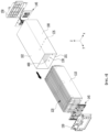
- FIG. 5 is an exploded perspective view of a battery module according to an embodiment of the present disclosure.
- FIG. 8 is a cross-sectional view taken along line B-B′ of FIG. 7 ;
- FIG. 9 is a plan view illustrating one battery cell included in FIG. 8 ;
- FIG. 10 is a cross-sectional view of a battery module according to another embodiment of the present disclosure.
- the module frame 100 surrounds remaining outer surfaces except for the front surface and the rear surface of the battery cell stack 120 , end plates 150 are located on the front surface and the rear surface of the battery cell stack 120 , respectively, and busbar frames 145 are located between the battery cell stack 120 and the end plates 150 .
- the remaining surfaces except for the front surface and the rear surface of the battery cell stack 120 may be upper, lower, left, and right surfaces of the battery cell stack 120 .
- the upper surface 102 and the lower surface 101 of the module frame 100 may face each other along a direction perpendicular to a stack direction of the battery cell stack 120 .
- the stack direction of the battery cell stack 120 may be the x-axis direction of FIG. 5
- the direction perpendicular to the stack direction may be the z-axis direction.
- a first adhesive layer 250 may be formed between the adjacent battery cells, among the plurality of battery cells 110 .
- the first adhesive layer 250 may be a double-sided tape.
- the first adhesive layer 250 may be formed adjacent to the thermally conductive resin layer 400 .
- the first adhesive layer 250 may be formed at ends of the space part formed between the adjacent battery cells.
- the first adhesive layer 250 may make contact with the thermally conductive resin layer 400 .
- the cell block may be a structure, in which the busbar frame 145 of FIG. 5 is coupled to the battery cell stack 120 .
- the battery module according to the present embodiment may further include a blocking film 270 located between the battery cell stack 120 and the thermally conductive resin layer 400 .
- the blocking film 270 may be formed of a polymer film, and, for example, may be formed of a polyethylene terephthalate (PET) film.
- PET polyethylene terephthalate
- the blocking film 270 according to the present embodiment may cover the first adhesive layer 250 and the second adhesive layer 260 . That is, as illustrated in FIG. 10 , the blocking film 270 is a structure that extends long in a transverse direction between the battery cell stack 120 and the thermally conductive resin layer 400 , and may extend to the compression pad 180 located at opposite peripheries of the module frame 100 .
- the thermally conductive resin can be prevented from permeating between the adjacent battery cells and/or between the compression pad 180 and the outermost battery cell 110 , by the blocking film 270 . Accordingly, the degree of freedom of the formation locations of the first and second adhesive layers 250 and 260 can be increased.
- at least one group of the first adhesive layer 250 and the second adhesive layer 260 may be formed to be slightly spaced apart from the blocking film 270 , and unlike this, at least one group of the first adhesive layer 250 and the second adhesive layer 260 may make contact with the blocking film 270 . Further, at least one of the first adhesive layer 250 and the second adhesive layer 260 may be located at central portions of the battery cell 110 .
- FIG. 11 is a cross-sectional view illustrating a modified example of a blocking film of FIG. 10 .
- the above-mentioned battery module and a battery pack including the same may be applied to various devices. These devices may be applied to vehicles such as an electric bicycle, an electric vehicle, a hybrid vehicle, but the present disclosure is not limited thereto but can be applied to various devices that can use the battery module and the battery pack including the same, which also belongs to the scope of the present disclosure.
Landscapes
- Chemical & Material Sciences (AREA)
- Chemical Kinetics & Catalysis (AREA)
- Electrochemistry (AREA)
- General Chemical & Material Sciences (AREA)
- Engineering & Computer Science (AREA)
- Manufacturing & Machinery (AREA)
- Aviation & Aerospace Engineering (AREA)
- Battery Mounting, Suspending (AREA)
- Connection Of Batteries Or Terminals (AREA)
- Secondary Cells (AREA)
Abstract
Description
-
- 100: module frame
- 120: battery cell stack
- 135: liquid injection hole
- 250, 260: adhesive layers
- 270: blocking film
- 400: thermally conductive resin layer
Claims (7)
Applications Claiming Priority (3)
| Application Number | Priority Date | Filing Date | Title |
|---|---|---|---|
| KR1020190145142A KR102398575B1 (en) | 2019-11-13 | 2019-11-13 | Battery module and battery pack including the same |
| KR10-2019-0145142 | 2019-11-13 | ||
| PCT/KR2020/008793 WO2021096020A1 (en) | 2019-11-13 | 2020-07-06 | Battery module and battery pack including same |
Publications (2)
| Publication Number | Publication Date |
|---|---|
| US20220158271A1 US20220158271A1 (en) | 2022-05-19 |
| US12278355B2 true US12278355B2 (en) | 2025-04-15 |
Family
ID=75912145
Family Applications (1)
| Application Number | Title | Priority Date | Filing Date |
|---|---|---|---|
| US17/439,545 Active 2042-05-26 US12278355B2 (en) | 2019-11-13 | 2020-07-06 | Battery module and battery pack including the same |
Country Status (7)
| Country | Link |
|---|---|
| US (1) | US12278355B2 (en) |
| EP (1) | EP3930079B1 (en) |
| JP (1) | JP7229589B2 (en) |
| KR (1) | KR102398575B1 (en) |
| CN (1) | CN113711430B (en) |
| ES (1) | ES3053090T3 (en) |
| WO (1) | WO2021096020A1 (en) |
Families Citing this family (9)
| Publication number | Priority date | Publication date | Assignee | Title |
|---|---|---|---|---|
| KR102924941B1 (en) | 2020-08-13 | 2026-02-09 | 에스케이온 주식회사 | Battery module |
| KR20230049454A (en) * | 2021-10-06 | 2023-04-13 | 주식회사 엘지에너지솔루션 | Battery module and battery pack including the same |
| WO2023229171A1 (en) * | 2022-05-25 | 2023-11-30 | 주식회사 엘지에너지솔루션 | Battery module and manufacturing method therefor |
| CA3214672A1 (en) | 2022-10-03 | 2024-04-03 | Oasis Aerospace Inc. | Battery module clamshell |
| KR20240079058A (en) * | 2022-11-28 | 2024-06-04 | 주식회사 엘지에너지솔루션 | Battery sub module |
| KR20240100809A (en) | 2022-12-23 | 2024-07-02 | 주식회사 엘지에너지솔루션 | Easy-to-disassemble battery pack |
| WO2024135970A1 (en) * | 2022-12-23 | 2024-06-27 | 주식회사 엘지에너지솔루션 | Battery pack and vehicle comprising same |
| GB2632699A (en) * | 2023-08-18 | 2025-02-19 | Jaguar Land Rover Ltd | Vehicle battery pack disassembly |
| KR20250066011A (en) * | 2023-11-06 | 2025-05-13 | 주식회사 엘지에너지솔루션 | Battery module with improved cooling performance and battery pack including the same |
Citations (29)
| Publication number | Priority date | Publication date | Assignee | Title |
|---|---|---|---|---|
| JPH1186900A (en) | 1997-09-12 | 1999-03-30 | Ngk Insulators Ltd | Battery |
| US20030215702A1 (en) | 2002-05-08 | 2003-11-20 | Yuuji Tanjou | Secondary cell module and method of its production |
| JP2004111098A (en) | 2002-09-13 | 2004-04-08 | Nissan Motor Co Ltd | Secondary battery module and method of manufacturing the same |
| JP2006228714A (en) | 2005-01-21 | 2006-08-31 | Sony Corp | Battery pack |
| US20070224498A1 (en) | 2006-03-21 | 2007-09-27 | Lg Chem, Ltd | Battery module having the attachment members between battery cells |
| KR20110000003A (en) | 2009-06-26 | 2011-01-03 | 현대자동차일본기술연구소 | Laminate battery cell fixture |
| CN102272976A (en) | 2009-01-06 | 2011-12-07 | 株式会社Lg化学 | Spacer for battery pack and battery pack including same |
| US20140065455A1 (en) | 2012-09-06 | 2014-03-06 | Chia-Ming Chuang | Battery assembly with adhesive stop mechanism |
| JP2014093242A (en) | 2012-11-06 | 2014-05-19 | Nissan Motor Co Ltd | Battery unit |
| WO2014203342A1 (en) | 2013-06-19 | 2014-12-24 | 日立オートモティブシステムズ株式会社 | Battery module |
| US20150303425A1 (en) | 2012-11-20 | 2015-10-22 | Sk Innovation Co., Ltd. | Secondary battery module |
| KR20170021122A (en) | 2015-08-17 | 2017-02-27 | 주식회사 엘지화학 | Battery module, battery pack comprising the battery module and vehicle comprising the battery pack |
| KR20170043933A (en) | 2015-10-14 | 2017-04-24 | 주식회사 엘지화학 | Battery module and battery pack comprising the smae |
| WO2017139826A1 (en) | 2016-02-19 | 2017-08-24 | Avl List Gmbh | Battery |
| WO2017171509A1 (en) * | 2016-04-01 | 2017-10-05 | 주식회사 엘지화학 | Battery module |
| CN107431147A (en) | 2015-02-27 | 2017-12-01 | 株式会社Lg化学 | Battery module |
| KR20170135479A (en) | 2016-05-31 | 2017-12-08 | 주식회사 엘지화학 | Battery module, battery pack comprising the battery module and vehicle comprising the battery pack |
| US20180086472A1 (en) | 2016-09-25 | 2018-03-29 | Impossible Aerospace Corporation | Aircraft Battery Systems and Aircraft Including Same |
| KR20180071800A (en) | 2016-12-20 | 2018-06-28 | 주식회사 엘지화학 | Battery Module having improved energy density and simplified assembly process |
| KR20180084539A (en) | 2017-01-17 | 2018-07-25 | 주식회사 엘지화학 | Battery module, battery pack comprising the battery module and vehicle comprising the battery pack |
| CN108475831A (en) | 2016-08-18 | 2018-08-31 | 株式会社Lg化学 | Battery module |
| KR20180138027A (en) | 2017-06-20 | 2018-12-28 | 주식회사 엘지화학 | Battery pack and vehicle comprising the battery pack |
| US20190067656A1 (en) | 2017-08-31 | 2019-02-28 | Contemporary Amperex Technology Co., Limited | Frame and battery module |
| WO2019098491A1 (en) | 2017-11-14 | 2019-05-23 | 주식회사 엘지화학 | Battery module to which battery cell pressing-type end plate and expandable sensing housing structure are applied |
| US20190198952A1 (en) | 2017-12-26 | 2019-06-27 | Sk Innovation Co., Ltd. | Battery module and manufacturing method thereof |
| KR20190092835A (en) | 2018-01-31 | 2019-08-08 | 주식회사 엘지화학 | Top cover, battery module using the same, and battery pack and vehicle including the same |
| KR20190105731A (en) | 2018-03-06 | 2019-09-18 | 현대모비스 주식회사 | High voltage battery module |
| WO2019177275A1 (en) | 2018-03-13 | 2019-09-19 | 주식회사 엘지화학 | Battery module, battery pack comprising battery module and vehicle comprising battery pack |
| US20200067040A1 (en) * | 2018-08-21 | 2020-02-27 | Sk Innovation Co., Ltd. | Battery module and manufacturing method thereof |
Family Cites Families (2)
| Publication number | Priority date | Publication date | Assignee | Title |
|---|---|---|---|---|
| EP2849275B1 (en) | 2012-05-08 | 2017-05-03 | Lg Chem, Ltd. | Battery module including high-efficiency cooling structure |
| KR101943542B1 (en) * | 2015-09-21 | 2019-01-29 | 주식회사 엘지화학 | Battery module and battery pack comprising the same |
-
2019
- 2019-11-13 KR KR1020190145142A patent/KR102398575B1/en active Active
-
2020
- 2020-07-06 WO PCT/KR2020/008793 patent/WO2021096020A1/en not_active Ceased
- 2020-07-06 CN CN202080028622.9A patent/CN113711430B/en active Active
- 2020-07-06 US US17/439,545 patent/US12278355B2/en active Active
- 2020-07-06 JP JP2021545910A patent/JP7229589B2/en active Active
- 2020-07-06 EP EP20887663.1A patent/EP3930079B1/en active Active
- 2020-07-06 ES ES20887663T patent/ES3053090T3/en active Active
Patent Citations (47)
| Publication number | Priority date | Publication date | Assignee | Title |
|---|---|---|---|---|
| JPH1186900A (en) | 1997-09-12 | 1999-03-30 | Ngk Insulators Ltd | Battery |
| US20030215702A1 (en) | 2002-05-08 | 2003-11-20 | Yuuji Tanjou | Secondary cell module and method of its production |
| JP2004111098A (en) | 2002-09-13 | 2004-04-08 | Nissan Motor Co Ltd | Secondary battery module and method of manufacturing the same |
| JP2006228714A (en) | 2005-01-21 | 2006-08-31 | Sony Corp | Battery pack |
| US20070224498A1 (en) | 2006-03-21 | 2007-09-27 | Lg Chem, Ltd | Battery module having the attachment members between battery cells |
| CN102272976A (en) | 2009-01-06 | 2011-12-07 | 株式会社Lg化学 | Spacer for battery pack and battery pack including same |
| US20120028084A1 (en) | 2009-01-06 | 2012-02-02 | Lg Chem, Ltd | Spacer for battery pack and battery pack comprising the same |
| KR20110000003A (en) | 2009-06-26 | 2011-01-03 | 현대자동차일본기술연구소 | Laminate battery cell fixture |
| US9236593B2 (en) | 2012-09-06 | 2016-01-12 | Atieva, Inc. | Battery assembly with adhesive stop mechanism |
| US20140065455A1 (en) | 2012-09-06 | 2014-03-06 | Chia-Ming Chuang | Battery assembly with adhesive stop mechanism |
| CN103682191A (en) | 2012-09-06 | 2014-03-26 | 庄嘉明 | Frame battery pack with glue stop |
| JP2014093242A (en) | 2012-11-06 | 2014-05-19 | Nissan Motor Co Ltd | Battery unit |
| US20150303425A1 (en) | 2012-11-20 | 2015-10-22 | Sk Innovation Co., Ltd. | Secondary battery module |
| US20160126514A1 (en) | 2013-06-19 | 2016-05-05 | Hitachi Automotive Systems, Ltd. | Battery module |
| WO2014203342A1 (en) | 2013-06-19 | 2014-12-24 | 日立オートモティブシステムズ株式会社 | Battery module |
| US20180076493A1 (en) | 2015-02-27 | 2018-03-15 | Lg Chem, Ltd. | Battery module |
| JP2018510463A (en) | 2015-02-27 | 2018-04-12 | エルジー・ケム・リミテッド | Battery module |
| CN107431147A (en) | 2015-02-27 | 2017-12-01 | 株式会社Lg化学 | Battery module |
| KR20170021122A (en) | 2015-08-17 | 2017-02-27 | 주식회사 엘지화학 | Battery module, battery pack comprising the battery module and vehicle comprising the battery pack |
| KR20170043933A (en) | 2015-10-14 | 2017-04-24 | 주식회사 엘지화학 | Battery module and battery pack comprising the smae |
| US20180108881A1 (en) | 2015-10-14 | 2018-04-19 | Lg Chem, Ltd. | Battery module and battery pack including same |
| WO2017139826A1 (en) | 2016-02-19 | 2017-08-24 | Avl List Gmbh | Battery |
| WO2017171509A1 (en) * | 2016-04-01 | 2017-10-05 | 주식회사 엘지화학 | Battery module |
| US20180358592A1 (en) * | 2016-04-01 | 2018-12-13 | Lg Chem, Ltd. | Battery module |
| KR20170135479A (en) | 2016-05-31 | 2017-12-08 | 주식회사 엘지화학 | Battery module, battery pack comprising the battery module and vehicle comprising the battery pack |
| US20180294535A1 (en) | 2016-05-31 | 2018-10-11 | Lg Chem, Ltd. | Battery module, and battery pack and vehicle comprising the same |
| US20180375077A1 (en) | 2016-08-18 | 2018-12-27 | Lg Chem, Ltd. | Battery module |
| CN108475831A (en) | 2016-08-18 | 2018-08-31 | 株式会社Lg化学 | Battery module |
| US20180086472A1 (en) | 2016-09-25 | 2018-03-29 | Impossible Aerospace Corporation | Aircraft Battery Systems and Aircraft Including Same |
| KR20180071800A (en) | 2016-12-20 | 2018-06-28 | 주식회사 엘지화학 | Battery Module having improved energy density and simplified assembly process |
| US20200343607A1 (en) | 2017-01-17 | 2020-10-29 | Lg Chem, Ltd. | Battery Module, Battery Pack Including Battery Module, And Vehicle Including Battery Pack |
| KR20180084539A (en) | 2017-01-17 | 2018-07-25 | 주식회사 엘지화학 | Battery module, battery pack comprising the battery module and vehicle comprising the battery pack |
| EP3419103A1 (en) | 2017-01-17 | 2018-12-26 | LG Chem, Ltd. | Battery module, battery pack comprising such battery module, and vehicle comprising such battery pack |
| US20190051954A1 (en) | 2017-01-17 | 2019-02-14 | Lg Chem, Ltd. | Battery Module, Battery Pack Including Battery Module, And Vehicle Including Battery Pack |
| CN108780934A (en) | 2017-01-17 | 2018-11-09 | 株式会社Lg化学 | Battery module, battery pack including battery module, and vehicle including battery pack |
| KR20180138027A (en) | 2017-06-20 | 2018-12-28 | 주식회사 엘지화학 | Battery pack and vehicle comprising the battery pack |
| US20190067656A1 (en) | 2017-08-31 | 2019-02-28 | Contemporary Amperex Technology Co., Limited | Frame and battery module |
| CN109428020A (en) | 2017-08-31 | 2019-03-05 | 宁德时代新能源科技股份有限公司 | Frame and battery module |
| WO2019098491A1 (en) | 2017-11-14 | 2019-05-23 | 주식회사 엘지화학 | Battery module to which battery cell pressing-type end plate and expandable sensing housing structure are applied |
| US20200176745A1 (en) | 2017-11-14 | 2020-06-04 | Lg Chem, Ltd. | Battery module to which battery cell pressing-type end plate and expandable sensing housing structure are applied |
| CN109994798A (en) | 2017-12-26 | 2019-07-09 | Sk新技术株式会社 | Battery module and method of manufacturing the same |
| US20190198952A1 (en) | 2017-12-26 | 2019-06-27 | Sk Innovation Co., Ltd. | Battery module and manufacturing method thereof |
| KR20190092835A (en) | 2018-01-31 | 2019-08-08 | 주식회사 엘지화학 | Top cover, battery module using the same, and battery pack and vehicle including the same |
| KR20190105731A (en) | 2018-03-06 | 2019-09-18 | 현대모비스 주식회사 | High voltage battery module |
| WO2019177275A1 (en) | 2018-03-13 | 2019-09-19 | 주식회사 엘지화학 | Battery module, battery pack comprising battery module and vehicle comprising battery pack |
| US20200411924A1 (en) | 2018-03-13 | 2020-12-31 | Lg Chem, Ltd. | Battery Module, Battery Pack Comprising Battery Module and Vehicle Comprising Battery Pack |
| US20200067040A1 (en) * | 2018-08-21 | 2020-02-27 | Sk Innovation Co., Ltd. | Battery module and manufacturing method thereof |
Non-Patent Citations (4)
| Title |
|---|
| Extended European Search Report including Written Opinion for Application No. 20887663.1 dated May 11, 2022, pp. 1-9. |
| International Search Report for Application No. PCT/KR2020/008793 on Oct. 29, 2020, 3 pages. |
| Machine English translation of KR 10-2019-0105731 (Year: 2019). * |
| Search Report dated Nov. 28, 2022 from the Office Action for Chinese Application No. 202080028622.9 issued Dec. 5, 2022, 4 pages. [See p. 2-3, categorizing the cited references]. |
Also Published As
| Publication number | Publication date |
|---|---|
| US20220158271A1 (en) | 2022-05-19 |
| WO2021096020A1 (en) | 2021-05-20 |
| EP3930079A4 (en) | 2022-06-08 |
| KR20210058109A (en) | 2021-05-24 |
| EP3930079A1 (en) | 2021-12-29 |
| CN113711430B (en) | 2023-10-13 |
| CN113711430A (en) | 2021-11-26 |
| JP2022520353A (en) | 2022-03-30 |
| ES3053090T3 (en) | 2026-01-19 |
| KR102398575B1 (en) | 2022-05-13 |
| EP3930079B1 (en) | 2025-10-22 |
| JP7229589B2 (en) | 2023-02-28 |
Similar Documents
| Publication | Publication Date | Title |
|---|---|---|
| US12278355B2 (en) | Battery module and battery pack including the same | |
| EP3796462B1 (en) | Battery module, manufacturing method thereof and battery pack including battery module | |
| US12255299B2 (en) | Battery module, manufacturing method thereof and battery pack including battery module | |
| US12087928B2 (en) | Battery module and battery pack including the same | |
| US20220045383A1 (en) | Battery module, method of manufacturing the same and battery pack | |
| US12176557B2 (en) | Battery module and battery pack including the same | |
| US20230282925A1 (en) | Battery module and battery pack including the same | |
| US20240055690A1 (en) | Battery pack and method of manufacturing the same | |
| EP3926736A1 (en) | Battery module and battery pack including same | |
| US20230299431A1 (en) | Battery cell, battery module, and battery pack including the same | |
| CN113748564B (en) | Battery module and battery pack including the battery module | |
| US12388139B2 (en) | Battery module and battery pack including the same | |
| CN113812036A (en) | Battery module and battery pack including the same | |
| CN115088121B (en) | Battery module, battery pack including the battery module, and device including the battery pack | |
| US12418068B2 (en) | Battery module and battery pack including the same | |
| KR20210058111A (en) | Battery module and battery pack including the same | |
| KR20210063102A (en) | Battery module and battery pack including the same |
Legal Events
| Date | Code | Title | Description |
|---|---|---|---|
| FEPP | Fee payment procedure |
Free format text: ENTITY STATUS SET TO UNDISCOUNTED (ORIGINAL EVENT CODE: BIG.); ENTITY STATUS OF PATENT OWNER: LARGE ENTITY |
|
| AS | Assignment |
Owner name: LG ENERGY SOLUTION, LTD., KOREA, REPUBLIC OF Free format text: ASSIGNMENT OF ASSIGNORS INTEREST;ASSIGNORS:KANG, DAHOON;SEONG, JUNYEOB;JU, JAE HYEON;AND OTHERS;REEL/FRAME:057502/0090 Effective date: 20210809 |
|
| STPP | Information on status: patent application and granting procedure in general |
Free format text: DOCKETED NEW CASE - READY FOR EXAMINATION |
|
| STPP | Information on status: patent application and granting procedure in general |
Free format text: NON FINAL ACTION MAILED |
|
| STPP | Information on status: patent application and granting procedure in general |
Free format text: RESPONSE TO NON-FINAL OFFICE ACTION ENTERED AND FORWARDED TO EXAMINER |
|
| STPP | Information on status: patent application and granting procedure in general |
Free format text: FINAL REJECTION MAILED |
|
| STPP | Information on status: patent application and granting procedure in general |
Free format text: DOCKETED NEW CASE - READY FOR EXAMINATION |
|
| STPP | Information on status: patent application and granting procedure in general |
Free format text: NOTICE OF ALLOWANCE MAILED -- APPLICATION RECEIVED IN OFFICE OF PUBLICATIONS |
|
| STPP | Information on status: patent application and granting procedure in general |
Free format text: PUBLICATIONS -- ISSUE FEE PAYMENT VERIFIED |
|
| STCF | Information on status: patent grant |
Free format text: PATENTED CASE |