US12274886B2 - Multi leadless pacemaker and surgical device - Google Patents
Multi leadless pacemaker and surgical device Download PDFInfo
- Publication number
- US12274886B2 US12274886B2 US17/283,817 US202017283817A US12274886B2 US 12274886 B2 US12274886 B2 US 12274886B2 US 202017283817 A US202017283817 A US 202017283817A US 12274886 B2 US12274886 B2 US 12274886B2
- Authority
- US
- United States
- Prior art keywords
- pacemaker
- sensor
- wire
- atrial sensor
- atrial
- Prior art date
- Legal status (The legal status is an assumption and is not a legal conclusion. Google has not performed a legal analysis and makes no representation as to the accuracy of the status listed.)
- Active, expires
Links
Images


Classifications
-
- A—HUMAN NECESSITIES
- A61—MEDICAL OR VETERINARY SCIENCE; HYGIENE
- A61N—ELECTROTHERAPY; MAGNETOTHERAPY; RADIATION THERAPY; ULTRASOUND THERAPY
- A61N1/00—Electrotherapy; Circuits therefor
- A61N1/18—Applying electric currents by contact electrodes
- A61N1/32—Applying electric currents by contact electrodes alternating or intermittent currents
- A61N1/36—Applying electric currents by contact electrodes alternating or intermittent currents for stimulation
- A61N1/372—Arrangements in connection with the implantation of stimulators
- A61N1/37205—Microstimulators, e.g. implantable through a cannula
-
- A—HUMAN NECESSITIES
- A61—MEDICAL OR VETERINARY SCIENCE; HYGIENE
- A61N—ELECTROTHERAPY; MAGNETOTHERAPY; RADIATION THERAPY; ULTRASOUND THERAPY
- A61N1/00—Electrotherapy; Circuits therefor
- A61N1/18—Applying electric currents by contact electrodes
- A61N1/32—Applying electric currents by contact electrodes alternating or intermittent currents
- A61N1/36—Applying electric currents by contact electrodes alternating or intermittent currents for stimulation
- A61N1/372—Arrangements in connection with the implantation of stimulators
- A61N1/375—Constructional arrangements, e.g. casings
- A61N1/37512—Pacemakers
-
- A—HUMAN NECESSITIES
- A61—MEDICAL OR VETERINARY SCIENCE; HYGIENE
- A61N—ELECTROTHERAPY; MAGNETOTHERAPY; RADIATION THERAPY; ULTRASOUND THERAPY
- A61N1/00—Electrotherapy; Circuits therefor
- A61N1/18—Applying electric currents by contact electrodes
- A61N1/32—Applying electric currents by contact electrodes alternating or intermittent currents
- A61N1/36—Applying electric currents by contact electrodes alternating or intermittent currents for stimulation
- A61N1/362—Heart stimulators
- A61N1/365—Heart stimulators controlled by a physiological parameter, e.g. heart potential
- A61N1/36507—Heart stimulators controlled by a physiological parameter, e.g. heart potential controlled by gradient or slope of the heart potential
-
- A—HUMAN NECESSITIES
- A61—MEDICAL OR VETERINARY SCIENCE; HYGIENE
- A61N—ELECTROTHERAPY; MAGNETOTHERAPY; RADIATION THERAPY; ULTRASOUND THERAPY
- A61N1/00—Electrotherapy; Circuits therefor
- A61N1/18—Applying electric currents by contact electrodes
- A61N1/32—Applying electric currents by contact electrodes alternating or intermittent currents
- A61N1/36—Applying electric currents by contact electrodes alternating or intermittent currents for stimulation
- A61N1/372—Arrangements in connection with the implantation of stimulators
- A61N1/37211—Means for communicating with stimulators
- A61N1/37252—Details of algorithms or data aspects of communication system, e.g. handshaking, transmitting specific data or segmenting data
- A61N1/37288—Communication to several implantable medical devices within one patient
-
- A—HUMAN NECESSITIES
- A61—MEDICAL OR VETERINARY SCIENCE; HYGIENE
- A61N—ELECTROTHERAPY; MAGNETOTHERAPY; RADIATION THERAPY; ULTRASOUND THERAPY
- A61N1/00—Electrotherapy; Circuits therefor
- A61N1/18—Applying electric currents by contact electrodes
- A61N1/32—Applying electric currents by contact electrodes alternating or intermittent currents
- A61N1/36—Applying electric currents by contact electrodes alternating or intermittent currents for stimulation
- A61N1/372—Arrangements in connection with the implantation of stimulators
- A61N1/375—Constructional arrangements, e.g. casings
- A61N1/37518—Anchoring of the implants, e.g. fixation
-
- A—HUMAN NECESSITIES
- A61—MEDICAL OR VETERINARY SCIENCE; HYGIENE
- A61N—ELECTROTHERAPY; MAGNETOTHERAPY; RADIATION THERAPY; ULTRASOUND THERAPY
- A61N1/00—Electrotherapy; Circuits therefor
- A61N1/18—Applying electric currents by contact electrodes
- A61N1/32—Applying electric currents by contact electrodes alternating or intermittent currents
- A61N1/36—Applying electric currents by contact electrodes alternating or intermittent currents for stimulation
- A61N1/372—Arrangements in connection with the implantation of stimulators
- A61N1/375—Constructional arrangements, e.g. casings
- A61N1/3756—Casings with electrodes thereon, e.g. leadless stimulators
Definitions
- the present disclosure was made by Task Unique No. 190642, Task No. HI19C0642 under the support of the Korean Ministry of Health and Welfare.
- the research management institution for the above project is the Korea Health Industry Development Institute, the research business name is “Micro Medical Robot Commercialization Technology Development”, and the research project name is “Micro Medical Robot Commercialization Common Base Technology Development Center”.
- the host institute is the Korean Micro Medical Robot Research Institute, and the research period is from Jun. 12, 2019 to Dec. 31, 2022.
- the present disclosure relates to a multi leadless pacemaker and surgical device. More specifically, the present disclosure relates to a pacemaker module in which a case unit, a vertical movement guide, an atrial sensor, and a pacemaker are integrated.
- the pacemaker module according to the present disclosure is capable of preventing damage to the inside of a human body during implantation, and capable of controlling the heartbeat while measuring the microcurrent and current flow of a heart.
- a pacemaker is a device that controls the heartbeat by applying electrical stimulation to the heart, and is mainly applied to a patient who complains of symptoms of bradyarrhythmia.
- a disconnection of the lead may occur.
- a pacing defect may occur due to the disconnection of the lead, and a pocket infection that infects human tissue may occur at the inserted location.
- a paging defect may occur due to the displacement of the electrode early after the implantation of the pacemaker, and when the displacement of electrode occurs, an excessive burden may be placed on the patient, which inevitably leads to reoperation.
- a leadless pacemaker that does not use an electrode guide line has been developed.
- the leadless pacemaker is inserted through the inferior vena cava and is placed in a ventricle so as to control the heartbeat. Due to the removal of an electrode guide line, such a leadless pacemaker has an advantage over the conventional pacemaker in that there are no problems such as pocket infection, hematoma, a cosmetic disadvantage, and damage to an electrode guide line.
- the leadless pacemaker also has problems.
- the conventional leadless pacemaker is located in a ventricle and is difficult to measure a conduction process of the entire heart in the ventricle. Thus, it is difficult to accurately measure the conduction process of the entire heart.
- the inventors made a pacemaker module including a case unit, a vertical movement guide, an atrial sensor, and a pacemaker, and have found that there is an excellent effect in that the pacemaker module according to the present disclosure is capable of accurately measuring the flow of current in the entire heart and capable of being accurately and consistently operated with a simple operation, which makes it possible to accurately implant the pacemaker module.
- a pacemaker module including a case, a vertical movement guide, an atrial sensor, and a pacemaker.
- the present disclosure provides a use of a pacemaker module including a case, a vertical movement guide, an atrial sensor, and a pacemaker.
- the present disclosure relates to a multi leadless pacemaker and surgical device.
- the pacemaker module according to the present disclosure has advantages of being easy and simple to operate while being able to accurately measure the current flow in the heart.
- An aspect of the present disclosure relates to a pacemaker module including: a case unit through which a vertical movement guide wire, a atrial sensor re-coupling wire, and a pacemaker re-coupling wire pass; a vertical movement guide connected to the vertical movement guide wire and including a hole port through which the atrial sensor re-coupling wire and the pacemaker re-coupling wire pass; an atrial sensor connected to the atrial sensor re-coupling wire and including a first sensor; and a pacemaker connected to the pacemaker re-coupling wire and including a stimulation unit and a second sensor.
- the case unit may include, but is not limited to, any one or more materials selected from a group consisting of rubber, carbon composite, synthetic resin, polyurethane, silicone, polyethylene, pebax, and polypropylene.
- the case unit When the case unit includes a magnetic body, it is possible to freely and precisely drive the case unit within a human body using an external driving device.
- the external driving device may include a permanent magnet or an electromagnet.
- the external driving device By applying a magnetic field to the magnetic body of the case unit using the external driving device, it is possible for the user to freely move the pacemaker module within a human body only using the external driving device.
- the case unit may include an ejection port in one side thereof, and the vertical movement guide, the atrial sensor, and the pacemaker may move inside and outside the case unit through the ejection port.
- the vertical movement guide, the atrial sensor, and the pacemaker may be arranged in the order of the vertical movement guide, the atrial sensor, and the pacemaker from the side opposite to the ejection port.
- the case unit may have a rotational motion guide arranged on the inner surface thereof.
- the rotational motion guide may include a recess, and the recess may have a spiral shape.
- the pacemaker module may include a wire tube connected to one end of the case unit.
- the wire tube may include, but is not limited to, one or more selected from a group consisting of rubber, a carbon composite, a synthetic resin, polyurethane, synthetic fiber, silicone, polyethylene, nylon, carbon fiber, and polypropylene.
- the wire tube may include a tube including one or more one or more hollow interiors.
- the wire tube may include a vertical movement guide wire tube through which the vertical movement guide wire moves, an atrial sensor re-coupling wire tube through which the atrial sensor re-coupling wire moves, and a pacemaker re-coupling wire tube through which the pacemaker re-coupling wire moves.
- the pacemaker module may further include a manipulation unit connected to one end of the wire tube.
- the vertical movement guide is connected to the vertical movement guide wire. Accordingly, it is possible for the user to eject the atrial sensor and the pacemaker from the inside of the case unit to the outside of the case unit by manipulating the vertical movement guide wire to push the vertical movement guide wire to the outside of the case unit.
- the atrial sensor re-coupling wire may include a metal or synthetic fiber.
- the vertical movement guide wire may include, but is not limited to, one or more materials selected from a group consisting of a shape memory alloy, carbon fiber, and nylon.
- the pacemaker re-coupling wire may include a metal or synthetic fiber.
- the vertical movement guide wire may include, but is not limited to, one or more materials selected from a group consisting of a shape memory alloy, carbon fiber, and nylon.
- the atrial sensor is mounted in the atrium, and is capable of detecting and recording the ECG information of the heart, converting the ECG information into a digital signal, and outputting the digital signal to the outside.
- the atrial sensor detects electrocardiogram information of a heart.
- the detected electrocardiogram information may detect, but is not limited to, for example, P waves, a QRS group, T waves or a Q-T time, an A-H time, an H-V time, etc.
- the atrial sensor may include a transmission unit, and the transmission unit may transmit the ECG information of the heart measured by the atrial sensor to the pacemaker or a controller.
- the atrial sensor may include a first battery unit.
- the first battery unit may supply power for the operation of the atrial sensor and the first sensor, and the first battery unit may include a lithium ion battery, a fuel cell, or a biofuel cell.
- the first protrusion is arranged on a side surface portion of the atrial sensor to be engageable with the rotational motion guide, thereby stably coupling the atrial sensor inside the case unit.
- the first re-coupling loop may be arranged on one side of the atrial sensor, and the atrial sensor re-coupling wire may be connected to the first re-coupling loop.
- the stimulation unit may adjust stimulation intensity and intervals of stimulation pulses based on the atrial electrocardiogram information received from the atrial sensor and the electrical signal of the ventricle measured by the second sensor, and may output the cardiac stimulation pulses to the heart.
- the pacemaker may include a reception unit configured to receive a signal from the controller or the atrial sensor.
- the pacemaker may include a second battery unit.
- the stimulation unit may include an electrode.
- the pacemaker may include at least one second protrusion engageable with the rotational motion guide.
- the second protrusion may be arranged on a side surface portion of the pacemaker to be engageable with the rotational motion guide. Accordingly, the second protrusion may stably couple the pacemaker inside the case unit.
- an electrode may be arranged on the surface of the second protrusion.
- the pacemaker may include a second re-coupling loop.
- the second re-coupling loop may be arranged on one side of the pacemaker, and the pacemaker re-coupling wire may be connected to the second re-coupling loop.
- the pacemaker module may further include a controller.
- the controller may receive ECG information output from the atrial sensor and may output a control signal of the pacemaker based on the ECG information such that the pacemaker may output cardiac stimulation pulses that electrically stimulate the heart tissue.
- a first fixing part and a second fixing part may each have a linear shape, a curved shape, or a spiral shape.
- the first fixing part and the second fixing part may have, but is not limited to, a spiral shape for stable coupling with the heart tissue.
- the atrial sensor and the pacemaker may be connected to each other in a wireless or wired manner.
- the present disclosure relates to a pacemaker module including a case unit, a vertical movement guide, an atrial sensor, and a pacemaker.
- the pacemaker module according to the present disclosure has an excellent effect in that it is capable of accurately measuring the flow of current in the entire heart and capable of being accurately and consistently operated with a simple operation, which makes it possible to accurately implant the pacemaker module.
- FIG. 1 is a view illustrating a pacemaker module according to an embodiment of the present disclosure.
- FIG. 2 is a view illustrating a pacemaker module according to another embodiment of the present disclosure.
- FIG. 3 is a view illustrating a case unit, a vertical movement guide, and a vertical movement guide wire according to an embodiment of the present disclosure.
- FIG. 4 is a front view of a vertical movement guide according to an embodiment of the present disclosure.
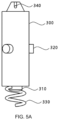
- FIG. 5 B is a front view of the atrial sensor according to an embodiment of the present disclosure.
- FIG. 6 A is a view illustrating a pacemaker according to an embodiment of the present disclosure.
- FIG. 6 C is a rear view of the pacemaker according to an embodiment of the present disclosure.
- FIG. 7 is a view illustrating movements of a vertical movement guide, a vertical movement guide wire, and a protrusion when an atrial sensor and a pacemaker are fixed in a pacemaker module according to an embodiment of the present disclosure.
- FIG. 8 is a view illustrating movements of a vertical movement guide, a vertical movement guide wire, and a protrusion during re-coupling of an atrial sensor or a pacemaker in a pacemaker module according to an embodiment of the present disclosure.
- FIG. 9 is a view illustrating a process of implanting a pacemaker module according to an embodiment of the present disclosure into a heart.
- FIG. 10 is a view illustrating a process of implanting a pacemaker module according to another embodiment of the present disclosure into a heart.
- a pacemaker module including: a case unit through which a vertical movement guide wire, a atrial sensor re-coupling wire, and a pacemaker re-coupling wire pass; a vertical movement guide connected to the vertical movement guide wire and including a hole port through which the atrial sensor re-coupling wire and the pacemaker re-coupling wire pass; an atrial sensor connected to the atrial sensor re-coupling wire and including a first sensor; and a pacemaker connected to the pacemaker re-coupling wire and including a stimulation unit and a second sensor.
- constituent element When a constituent element is referred to as being “connected” or “coupled” to another constituent element, it should be understood that the constituent element may be directly connected or coupled to the other element, but a still another constituent element may be present therebetween.
- FIG. 1 is a view illustrating a pacemaker module according to an embodiment of the present disclosure.
- a pacemaker module 1000 may include a case unit 100 , a vertical movement guide 200 , an atrial sensor 300 , a pacemaker 400 , a vertical movement guide wire 500 , an atrial sensor re-coupling wire 600 , a pacemaker re-coupling wire 700 , and may include a data transmission wire 800 .
- the case unit 100 may include a soft and flexible material.
- the case unit 100 may include one or more materials selected from a group consisting of rubber, a carbon composite, a synthetic resin, polyurethane, silicone, polyethylene, pebax, and polypropylene. Since the case unit includes a soft and flexible material, it is possible to move the pacemaker module while minimizing damage to human tissue when moving the pacemaker module within the human body.
- the case unit 100 may include an ejection port 105 in one side.
- the ejection port 105 may be located at a position opposite to the a magnetic body 110 , and the vertical movement guide 200 , the atrial sensor 300 , and the pacemaker 400 are movable to the inside and outside through the ejection port 105 in the case unit 100 .
- the case unit 100 may include a magnetic body 110 .
- the magnetic body may be, but is not limited to, iron, nickel, cobalt, or an alloy thereof, or a permanent magnet.
- the case unit 100 when the case unit 100 includes the magnetic body 110 , it is possible for a user to move the case unit 100 to a desired location in the human body by applying a magnetic field to the case unit 100 by manipulating an external driving device including a permanent magnet or an electromagnet.
- the wire tube 120 may be connected to one end of the case unit 100 .
- the wire tube 120 may include one or more materials selected from a group consisting of rubber, a carbon composite, a synthetic resin, polyurethane, synthetic fiber, silicone, polyethylene, nylon, carbon fiber, and polypropylene.
- a tube including one or more hollow interiors may be arranged inside the wire tube 120 .
- a vertical guide wire tube including a hollow interior, an atrial sensor re-coupling wire tube, and a pacemaker re-coupling wire tube may be arranged inside the wire tube.
- the wires move in respective tubes independent from each other, it is possible to minimize interference between the wires.
- a manipulation unit (not illustrated) may be arranged at the other end of the wire tube 120 . That is, a manipulation unit may be arranged at one end of the wire tube 120 opposite to the case unit 100 .
- the user may move the vertical movement guide 200 , the atrial sensor 300 , and the pacemaker 400 by manipulating each of the vertical movement guide wire tube 500 , the atrial sensor re-coupling wire tube 600 , and the pacemaker re-coupling wire tube 700 of the pacemaker module using the manipulation unit.
- the vertical movement guide wire 500 may be arranged to pass through the wire tube 120 and the case portion 100 and to be connected to the vertical movement guide 200 .
- the vertical movement guide wire 500 may include a metal or synthetic fiber, and may include, for example, one or more materials selected from a group consisting of a shape memory alloy, carbon fiber, or nylon.
- the vertical movement guide 200 may include a hole port through which the atrial sensor re-coupling wire 600 and the pacemaker re-coupling wire 700 pass, and may be arranged to be connected to the vertical movement guide wire 500 .
- the vertical movement guide 200 may include one or more hole ports, and may include, for example, two hole ports as illustrated in FIG. 4 .
- the atrial sensor 300 may be connected to the atrial sensor re-coupling wire 600 , and may include a first sensor 310 .
- the atrial sensor 300 may measure the electrical signals of the heart through the first sensor 310 , and, for example, the atrial sensor 300 may measure ECG information, such as P waves, a QRS group, T waves or a Q-T time, an A-H time, and an H-V time.
- ECG information such as P waves, a QRS group, T waves or a Q-T time, an A-H time, and an H-V time.
- One or more atrial sensor re-coupling wires 600 may be included.
- the pacemaker module 1000 may include two atrial sensor re-coupling wires.
- the atrial sensor re-coupling wires 600 may be arranged to pass through the wire tube 120 , the case unit 100 , and the vertical movement guide 200 , and to be connected to the atrial sensor 300 .
- Each of the atrial sensor re-coupling wires 600 may include a metal or synthetic fiber, and may include, for example, one or more materials selected from a group consisting of a shape memory alloy, carbon fiber, or nylon.
- the atrial sensor re-coupling wires 600 may be used to move the atrial sensor 300 ejected to the outside of the case unit 100 or to move the atrial sensor 300 toward the wire tube 120 in the case unit 100 . Specifically, it is possible for the user to move the atrial sensor 300 to the inside of the case unit 100 by moving the atrial sensor re-coupling wires 600 in a direction opposite to the ejection port 105 in the case unit 100 , that is, toward the wire tube using the manipulation unit.
- One or more pacemaker re-coupling wires 700 may be included.
- the pacemaker module 1000 may include two pacemaker re-coupling wires.
- the pacemaker re-coupling wires 700 may be arranged to pass through the wire tube 120 , the case unit 100 , and the vertical movement guide 200 and to be connected to the pacemaker 400 .
- Each of the pacemaker re-coupling wires 700 may include a metal or synthetic fiber, and may include, for example, one or more materials selected from a group consisting of a shape memory alloy, carbon fiber, or nylon.
- the atrial sensor 300 and the pacemaker 400 may be connected to each other in a wired manner. Therefore, after both the atrial sensor 300 and the pacemaker 400 are placed in the heart of a patient, the atrial sensor 300 and the pacemaker 400 is capable of exchanging electrical signals through the data transmission wire 800 . Specifically, the atrial sensor 300 is capable of transmitting measured ECG information to the pacemaker 400 through the data transmission wire 800 , and the pacemaker 400 is capable of outputting cardiac stimulation pulses to the heart of a patient based on the information measured by the atrial sensor 300 .
- FIG. 2 is a view illustrating a pacemaker module according to another embodiment of the present disclosure.
- a pacemaker module 2000 may include a case unit 100 , a vertical movement guide 200 , an atrial sensor 300 , a pacemaker 400 , a vertical movement guide wire 500 , an atrial sensor re-coupling wire 600 , and a pacemaker re-coupling wire 700 .
- the atrial sensor 300 and the pacemaker 400 may be connected to each other in a wireless manner. Accordingly, after both the atrial sensor 300 and the pacemaker 400 are arranged in the heart of a patient, the ECG information measured by the atrial sensor 300 is capable of being transmitted to the pacemaker 400 in a wireless form, and the pacemaker 400 is capable of outputting cardiac stimulation pulses to the heart of the patient based on the information measured by the atrial sensor.
- a rotational motion guide 130 may be arranged on the inner surface of the case unit 100 .
- the rotational motion guide 130 may be arranged on the inner surface along the longitudinal direction of the case unit 100 .
- the rotational motion guide 130 may include a recess, and the recess may have a curved, straight, or spiral shape, and may be, for example, a spiral shape as illustrated in FIG. 3 .
- the rotational motion guide 130 includes the spiral recess
- the vertical movement guide 200 moves linearly by the user, and the atrial sensor 300 and the pacemaker 400 rotate while being pushed to the ejection port in the case unit by the vertical movement guide 200 , which moves linearly, thereby providing a force to cause the fixing part to penetrate a heart portion.
- the atrial sensor 300 may include a first sensor 310 , a first protrusion 320 , a first fixing part 330 , and a first re-coupling loop 340 .
- the first sensor 310 may be arranged at one end of the atrial sensor 300 , and may measure the ECG information of a heart and an atrium.
- the atrial sensor 300 may include one or more first protrusions 320 .
- the first protrusion 320 may have a diameter corresponding to the width of the rotational motion guide 130 .
- the first protrusion 320 may be arranged on the side surface of the atrial sensor 300 . Accordingly, the first protrusion 320 is engageable with the recess in the rotational motion guide 130 of the case unit 100 , and is capable of causing the atrial sensor 300 to rotate and move inside the case unit 100 .
- the first fixing unit 330 may be arranged at one end of the atrial sensor 300 .
- the first fixing part 330 may be formed in a straight line, curved line, or spiral shape, and may be formed in a spiral shape as illustrated in FIG. 5 A .
- the first fixing part 330 when the atrial sensor 300 rotates, the first fixing part 330 also rotates at the same time and penetrates into the heart tissue to stably fix the atrial sensor to the heart of a patient.
- the atrial sensor 300 may include a first battery unit (not illustrated), and the first battery unit may supply power for driving the atrial sensor.
- the first battery unit may include a lithium ion battery, a fuel cell, or a biofuel cell.
- the atrial sensor 300 may include a transmission unit (not illustrated), and the transmission unit may transmit the electrocardiogram information of a heart measured by the atrial sensor to the pacemaker.
- FIG. 6 A is a view illustrating a pacemaker according to an embodiment of the present disclosure
- FIG. 6 B is a front view of the pacemaker according to an embodiment of the present disclosure
- FIG. 6 C is a rear view of the pacemaker according to an embodiment of the present disclosure.
- a pacemaker 400 may include a second sensor 410 , a magnetic pole unit (not illustrated), a second protrusion 420 , a second fixing part 430 , and a second re-coupling loop 440 .
- the stimulation unit (not illustrated) may be arranged inside or outside the pacemaker 400 , and the stimulation unit may output cardiac stimulation pulses.
- the stimulation unit (not illustrated) may include electrodes 425 a and 425 b.
- the second sensor 410 may be arranged at one end of the pacemaker 400 , and may measure electrical signals from a ventricle.
- the electrode 425 a may be arranged on a surface of the second sensor 410 , and the stimulation unit may output cardiac stimulation pulses through the electrode 425 b arranged on the surface of the second sensor 410 .
- the electrode 425 b may be arranged on the surface of the second protrusion 420 . Accordingly, the stimulation unit may output cardiac stimulation pulses through the electrode of the second protrusion 420 , and accordingly, the cardiac stimulation pulses may also be output from a side surface portion of the pacemaker 400 .
- the second fixing part 430 may be arranged at one end of the pacemaker 400 .
- the second fixing part 430 may be formed in a straight line, curved line or spiral shape, and may be formed in a spiral shape as illustrated in FIG. 6 A .
- the second fixing part 430 when the pacemaker 400 rotates, the second fixing part 430 also rotates at the same time and penetrates into the heart tissue to stably fix the pacemaker to the heart of a patient.
- the pacemaker 400 may include at least one second re-coupling loop 440 , and the second re-coupling loop 440 may be arranged at the other end of the pacemaker 400 .
- the pacemaker 400 may include two second re-coupling loops 440 . When two or more second re-coupling loops 440 are included, at least one pacemaker re-coupling wire 700 is fixed to each of the second re-coupling loop, thereby enabling the pacemaker to move in a more balanced manner.
- the pacemaker 400 may include a reception unit (not illustrated) configured to receive an electrical signal from the atrial sensor 300 .
- the vertical movement guide 200 pushes the atrial sensor 300 and the pacemaker 400 toward the ejection port 105 .
- the side surfaces of the atrial sensor 300 and the pacemaker 400 include protrusions 320 and 420 , which are engaged with recess in the rotational motion guide 130 , the protrusions spirally move along the recess.
- the atrial sensor 300 and the pacemaker 400 are movable to the outside of the case unit 100 while moving.
- the atrial sensor re-coupling wire 600 and the pacemaker re-coupling wire 700 toward the wire tube 120 it is possible for the user to move the atrial sensor 300 and the pacemaker 400 into the case unit 100 .
- the atrial sensor 300 or the pacemaker 400 is directed to the inside of the case unit, the atrial sensor 300 or the pacemaker 400 is introduced into the inside of the case unit while being rotated by the protrusions arranged on the side surface thereof and the rotational motion guide 130 , as described above.
- the atrial sensor and pacemaker are placed inside the case unit, the atrial sensor 300 and the pacemaker 400 are stably fixed inside the case unit by the protrusions.
- FIG. 9 is a view illustrating a process of implanting a pacemaker module according to an embodiment of the present disclosure into a heart
- FIG. 10 is a view illustrating a process of implanting a pacemaker module according to another embodiment of the present disclosure into a heart.
- the user may place the atrial sensor and the pacemaker of a pacemaker module in the heart of a patient.
- the user moves the pacemaker module to the right ventricle through the right atrium through the inferior vena cava, implants and fixes the pacemaker 400 on the inner wall of the right ventricle by manipulating the vertical movement guide, and checks the operation of the pacemaker module.
- the pacemaker is ejected to the outside of the case while rotating, and accordingly, the second fixing part 430 is firmly fixed to the heart tissue.
- the user moves the pacemaker module back to the right atrium, implants and fixes the atrial sensor 300 by manipulating the vertical movement guide 200 once again, and checks the operation of the pacemaker module.
- the user draws out the case unit 100 , the atrial sensor re-coupling wire 500 , and the pacemaker re-coupling wire 600 through the inferior vena cava, thereby finishing the implantation process.
- the implanted atrial sensor 300 and pacemaker 400 is capable of measuring ECG information of a patient and capable of applying appropriate cardiac stimulation pulses while transmitting and receiving data in a wired or wireless manner.
- the user during the implantation process, it is possible for the user to precisely and consistently move the pacemaker modules 1000 and 2000 to a desired location through the magnetic body 100 included in the case unit 100 .
- the pacemaker module can be accurately implanted into the heart of a patient without being greatly restricted by the skill of a practitioner.
- 100 case unit, 200 : vertical movement guide, 300 : atrial sensor, 400 : pacemaker, 500 : vertical movement guide wire, 600 : atrial sensor re-coupling wire, 700 : pacemaker re-coupling wire, 800 : data transmission wire, 105 : ejection port, 130 : rotational motion guide, 310 : first sensor, 320 : first protrusion, 330 : first fixing part, 340 : first re-coupling loop, 410 : second sensor, 420 : second protrusion, 430 : second fixing part, 440 : second re-coupling loop
Landscapes
- Health & Medical Sciences (AREA)
- Life Sciences & Earth Sciences (AREA)
- Animal Behavior & Ethology (AREA)
- Nuclear Medicine, Radiotherapy & Molecular Imaging (AREA)
- Radiology & Medical Imaging (AREA)
- Biomedical Technology (AREA)
- Engineering & Computer Science (AREA)
- General Health & Medical Sciences (AREA)
- Public Health (AREA)
- Veterinary Medicine (AREA)
- Heart & Thoracic Surgery (AREA)
- Cardiology (AREA)
- Biophysics (AREA)
- Physiology (AREA)
- Electrotherapy Devices (AREA)
Abstract
Description
Claims (7)
Applications Claiming Priority (3)
| Application Number | Priority Date | Filing Date | Title |
|---|---|---|---|
| KR1020200119255A KR102501306B1 (en) | 2020-09-16 | 2020-09-16 | Multi leadless pacemaker and surgical device |
| KR10-2020-0119255 | 2020-09-16 | ||
| PCT/KR2020/015198 WO2022059840A1 (en) | 2020-09-16 | 2020-11-03 | Multi leadless pacemaker and surgical device |
Publications (2)
| Publication Number | Publication Date |
|---|---|
| US20220305274A1 US20220305274A1 (en) | 2022-09-29 |
| US12274886B2 true US12274886B2 (en) | 2025-04-15 |
Family
ID=80777035
Family Applications (1)
| Application Number | Title | Priority Date | Filing Date |
|---|---|---|---|
| US17/283,817 Active 2042-08-18 US12274886B2 (en) | 2020-09-16 | 2020-11-03 | Multi leadless pacemaker and surgical device |
Country Status (3)
| Country | Link |
|---|---|
| US (1) | US12274886B2 (en) |
| KR (1) | KR102501306B1 (en) |
| WO (1) | WO2022059840A1 (en) |
Families Citing this family (1)
| Publication number | Priority date | Publication date | Assignee | Title |
|---|---|---|---|---|
| CN115253068B (en) * | 2022-08-08 | 2026-02-27 | 郭成军 | A detachable leadless pacemaker system with a paced cardiac conduction bundle |
Citations (16)
| Publication number | Priority date | Publication date | Assignee | Title |
|---|---|---|---|---|
| US6505082B1 (en) | 1998-07-22 | 2003-01-07 | Cardiac Pacemakers, Inc. | Single pass lead system |
| US20040006301A1 (en) * | 1999-09-20 | 2004-01-08 | Sell Jonathan C. | Magnetically guided myocardial treatment system |
| US20060052656A1 (en) * | 2004-09-09 | 2006-03-09 | The Regents Of The University Of California | Implantable devices using magnetic guidance |
| US20060142829A1 (en) * | 2004-12-23 | 2006-06-29 | Siemens Aktiengesellschaft | Intravenous pacemaker electrode |
| US20090018599A1 (en) * | 2006-09-13 | 2009-01-15 | Boston Scientific Scimed, Inc. | Cardiac Stimulation Using Leadless Electrode Assemblies |
| US20100125311A1 (en) * | 2008-11-18 | 2010-05-20 | National Chiao Tung University | Adjustable implant electrode system and implant electrode assembly thereof |
| US20140172034A1 (en) * | 2012-12-18 | 2014-06-19 | Pacesetter, Inc. | Intra-cardiac implantable medical device with ic device extension for lv pacing/sensing |
| US20150088155A1 (en) * | 2013-09-23 | 2015-03-26 | Cardiac Pacemakers, Inc. | Mechanical configurations for a multi-site leadless pacemaker |
| US20160067490A1 (en) * | 2014-09-08 | 2016-03-10 | Medtronic, Inc. | Dual chamber timing for leadless pacemakers using infrequent atrial signals and ventricular contractions |
| US20160310723A1 (en) * | 2015-04-24 | 2016-10-27 | Medtronic, Inc. | Intracardiac medical device |
| US20160310726A1 (en) * | 2015-04-23 | 2016-10-27 | Medtronic, Inc. | Intracardiac medical device |
| US20180021581A1 (en) | 2016-07-20 | 2018-01-25 | Cardiac Pacemakers, Inc. | Method and system for utilizing an atrial contraction timing fiducial in a leadless cardiac pacemaker system |
| US20180028805A1 (en) * | 2016-07-29 | 2018-02-01 | Medtronic, Inc. | Interventional medical systems and associated tethering assemblies and methods |
| US20190038906A1 (en) * | 2017-08-03 | 2019-02-07 | Cardiac Pacemakers, Inc. | Delivery devices and methods for leadless cardiac devices |
| US20210069517A1 (en) * | 2019-09-11 | 2021-03-11 | Cardiac Pacemakers, Inc. | Tools and systems for implanting and/or retrieving a leadless cardiac pacing device with helix fixation |
| US11154706B1 (en) * | 2018-01-31 | 2021-10-26 | Newpace Ltd. | Pill pacemaker with Bi-V pacing, DDD pacing and AAI with DDD backup pacing |
Family Cites Families (8)
| Publication number | Priority date | Publication date | Assignee | Title |
|---|---|---|---|---|
| US5628777A (en) * | 1993-07-14 | 1997-05-13 | Pacesetter, Inc. | Implantable leads incorporating cardiac wall acceleration sensors and method of fabrication |
| US6999821B2 (en) * | 2002-01-18 | 2006-02-14 | Pacesetter, Inc. | Body implantable lead including one or more conductive polymer electrodes and methods for fabricating same |
| EP2471450A1 (en) | 2005-10-14 | 2012-07-04 | Nanostim, Inc. | Leadless cardiac pacemaker and system |
| US8019419B1 (en) * | 2007-09-25 | 2011-09-13 | Dorin Panescu | Methods and apparatus for leadless, battery-less, wireless stimulation of tissue |
| US9216285B1 (en) * | 2014-12-18 | 2015-12-22 | Pacesetter, Inc. | Leadless implantable medical device having removable and fixed components |
| EP3256043B1 (en) * | 2015-02-12 | 2020-03-18 | Foundry Innovation & Research 1, Ltd. | Implantable devices for heart failure monitoring |
| WO2019046205A1 (en) * | 2017-08-26 | 2019-03-07 | Macdonald, Stuart | Cardiac annuloplasty and pacing procedures, related devices and methods |
| KR102111316B1 (en) * | 2018-02-22 | 2020-05-18 | 전남대학교산학협력단 | Active catheter system steered by an external electromagnetic actuation |
-
2020
- 2020-09-16 KR KR1020200119255A patent/KR102501306B1/en active Active
- 2020-11-03 US US17/283,817 patent/US12274886B2/en active Active
- 2020-11-03 WO PCT/KR2020/015198 patent/WO2022059840A1/en not_active Ceased
Patent Citations (16)
| Publication number | Priority date | Publication date | Assignee | Title |
|---|---|---|---|---|
| US6505082B1 (en) | 1998-07-22 | 2003-01-07 | Cardiac Pacemakers, Inc. | Single pass lead system |
| US20040006301A1 (en) * | 1999-09-20 | 2004-01-08 | Sell Jonathan C. | Magnetically guided myocardial treatment system |
| US20060052656A1 (en) * | 2004-09-09 | 2006-03-09 | The Regents Of The University Of California | Implantable devices using magnetic guidance |
| US20060142829A1 (en) * | 2004-12-23 | 2006-06-29 | Siemens Aktiengesellschaft | Intravenous pacemaker electrode |
| US20090018599A1 (en) * | 2006-09-13 | 2009-01-15 | Boston Scientific Scimed, Inc. | Cardiac Stimulation Using Leadless Electrode Assemblies |
| US20100125311A1 (en) * | 2008-11-18 | 2010-05-20 | National Chiao Tung University | Adjustable implant electrode system and implant electrode assembly thereof |
| US20140172034A1 (en) * | 2012-12-18 | 2014-06-19 | Pacesetter, Inc. | Intra-cardiac implantable medical device with ic device extension for lv pacing/sensing |
| US20150088155A1 (en) * | 2013-09-23 | 2015-03-26 | Cardiac Pacemakers, Inc. | Mechanical configurations for a multi-site leadless pacemaker |
| US20160067490A1 (en) * | 2014-09-08 | 2016-03-10 | Medtronic, Inc. | Dual chamber timing for leadless pacemakers using infrequent atrial signals and ventricular contractions |
| US20160310726A1 (en) * | 2015-04-23 | 2016-10-27 | Medtronic, Inc. | Intracardiac medical device |
| US20160310723A1 (en) * | 2015-04-24 | 2016-10-27 | Medtronic, Inc. | Intracardiac medical device |
| US20180021581A1 (en) | 2016-07-20 | 2018-01-25 | Cardiac Pacemakers, Inc. | Method and system for utilizing an atrial contraction timing fiducial in a leadless cardiac pacemaker system |
| US20180028805A1 (en) * | 2016-07-29 | 2018-02-01 | Medtronic, Inc. | Interventional medical systems and associated tethering assemblies and methods |
| US20190038906A1 (en) * | 2017-08-03 | 2019-02-07 | Cardiac Pacemakers, Inc. | Delivery devices and methods for leadless cardiac devices |
| US11154706B1 (en) * | 2018-01-31 | 2021-10-26 | Newpace Ltd. | Pill pacemaker with Bi-V pacing, DDD pacing and AAI with DDD backup pacing |
| US20210069517A1 (en) * | 2019-09-11 | 2021-03-11 | Cardiac Pacemakers, Inc. | Tools and systems for implanting and/or retrieving a leadless cardiac pacing device with helix fixation |
Also Published As
| Publication number | Publication date |
|---|---|
| KR102501306B1 (en) | 2023-02-21 |
| WO2022059840A1 (en) | 2022-03-24 |
| KR20220036719A (en) | 2022-03-23 |
| US20220305274A1 (en) | 2022-09-29 |
Similar Documents
| Publication | Publication Date | Title |
|---|---|---|
| US11724104B2 (en) | Epicardial lead design | |
| JP6902617B2 (en) | Leadless pacing device and its positioning system | |
| JP6888112B2 (en) | Leadless pacing device for treating cardiac arrhythmias | |
| US8983619B2 (en) | Testing communication during implantation | |
| EP1968698B1 (en) | Intra cardiac device | |
| CN111699019B (en) | Recharging of implanted medical devices | |
| AU2013337780B2 (en) | Wireless implantable sensing devices | |
| EP2769750B1 (en) | System for leadless pacing of the heart | |
| US12280263B2 (en) | Leadless cardiac pacemaker device configured to provide his bundle pacing | |
| US20110022113A1 (en) | Analyzer Compatible Communication Protocol | |
| US20150088155A1 (en) | Mechanical configurations for a multi-site leadless pacemaker | |
| US20130023975A1 (en) | Intravascular medical device with advancable electrode | |
| CN110214403A (en) | Recharging of Implanted Medical Devices | |
| CN107787239A (en) | Medical Devices Inside the Heart | |
| CN107206243A (en) | System and method for treating cardiac arrhythmia | |
| US9216280B1 (en) | Endovascular electrode system for tissue stimulation | |
| CN110636881B (en) | Antennas for Implantable Medical Devices | |
| US12274886B2 (en) | Multi leadless pacemaker and surgical device | |
| US10500394B1 (en) | Pacemaker system equipped with a flexible intercostal generator | |
| JP2021041168A (en) | Leadless pacemaker and methods for electrically stimulating cardiac tissue, sensing electrical signals and communicating between leadless pacemaker and external device | |
| WO2025061068A1 (en) | Implant delivery system, cardiac rhythm adjustment system, and cardiac rhythm adjustment method | |
| WO2025191396A1 (en) | Medical device telemetry extender | |
| WO2022233633A1 (en) | Intra-body network system |
Legal Events
| Date | Code | Title | Description |
|---|---|---|---|
| AS | Assignment |
Owner name: KOREA INSTITUTE OF MEDICAL MICROROBOTICS, KOREA, REPUBLIC OF Free format text: ASSIGNMENT OF ASSIGNORS INTEREST;ASSIGNORS:PARK, JONG-OH;KIM, CHANG-SEI;HONG, AYOUNG;AND OTHERS;REEL/FRAME:055867/0617 Effective date: 20210407 Owner name: INDUSTRY FOUNDATION OF CHONNAM NATIONAL UNIVERSITY, KOREA, REPUBLIC OF Free format text: ASSIGNMENT OF ASSIGNORS INTEREST;ASSIGNORS:PARK, JONG-OH;KIM, CHANG-SEI;HONG, AYOUNG;AND OTHERS;REEL/FRAME:055867/0617 Effective date: 20210407 |
|
| FEPP | Fee payment procedure |
Free format text: ENTITY STATUS SET TO UNDISCOUNTED (ORIGINAL EVENT CODE: BIG.); ENTITY STATUS OF PATENT OWNER: SMALL ENTITY |
|
| FEPP | Fee payment procedure |
Free format text: ENTITY STATUS SET TO SMALL (ORIGINAL EVENT CODE: SMAL); ENTITY STATUS OF PATENT OWNER: SMALL ENTITY |
|
| STPP | Information on status: patent application and granting procedure in general |
Free format text: DOCKETED NEW CASE - READY FOR EXAMINATION |
|
| STPP | Information on status: patent application and granting procedure in general |
Free format text: NON FINAL ACTION MAILED |
|
| STPP | Information on status: patent application and granting procedure in general |
Free format text: FINAL REJECTION MAILED |
|
| STPP | Information on status: patent application and granting procedure in general |
Free format text: DOCKETED NEW CASE - READY FOR EXAMINATION |
|
| STPP | Information on status: patent application and granting procedure in general |
Free format text: NON FINAL ACTION MAILED |
|
| STPP | Information on status: patent application and granting procedure in general |
Free format text: RESPONSE TO NON-FINAL OFFICE ACTION ENTERED AND FORWARDED TO EXAMINER |
|
| STPP | Information on status: patent application and granting procedure in general |
Free format text: EX PARTE QUAYLE ACTION MAILED |
|
| STPP | Information on status: patent application and granting procedure in general |
Free format text: RESPONSE TO EX PARTE QUAYLE ACTION ENTERED AND FORWARDED TO EXAMINER |
|
| STPP | Information on status: patent application and granting procedure in general |
Free format text: NOTICE OF ALLOWANCE MAILED -- APPLICATION RECEIVED IN OFFICE OF PUBLICATIONS |
|
| STCF | Information on status: patent grant |
Free format text: PATENTED CASE |