US12272055B2 - Image processing device, image processing method, and image processing program - Google Patents
Image processing device, image processing method, and image processing program Download PDFInfo
- Publication number
- US12272055B2 US12272055B2 US17/821,799 US202217821799A US12272055B2 US 12272055 B2 US12272055 B2 US 12272055B2 US 202217821799 A US202217821799 A US 202217821799A US 12272055 B2 US12272055 B2 US 12272055B2
- Authority
- US
- United States
- Prior art keywords
- composite
- band
- image
- interest
- tomographic
- Prior art date
- Legal status (The legal status is an assumption and is not a legal conclusion. Google has not performed a legal analysis and makes no representation as to the accuracy of the status listed.)
- Active, expires
Links
Images


Classifications
-
- A—HUMAN NECESSITIES
- A61—MEDICAL OR VETERINARY SCIENCE; HYGIENE
- A61B—DIAGNOSIS; SURGERY; IDENTIFICATION
- A61B6/00—Apparatus or devices for radiation diagnosis; Apparatus or devices for radiation diagnosis combined with radiation therapy equipment
- A61B6/02—Arrangements for diagnosis sequentially in different planes; Stereoscopic radiation diagnosis
- A61B6/025—Tomosynthesis
-
- A—HUMAN NECESSITIES
- A61—MEDICAL OR VETERINARY SCIENCE; HYGIENE
- A61B—DIAGNOSIS; SURGERY; IDENTIFICATION
- A61B6/00—Apparatus or devices for radiation diagnosis; Apparatus or devices for radiation diagnosis combined with radiation therapy equipment
- A61B6/50—Apparatus or devices for radiation diagnosis; Apparatus or devices for radiation diagnosis combined with radiation therapy equipment specially adapted for specific body parts; specially adapted for specific clinical applications
- A61B6/502—Apparatus or devices for radiation diagnosis; Apparatus or devices for radiation diagnosis combined with radiation therapy equipment specially adapted for specific body parts; specially adapted for specific clinical applications for diagnosis of breast, i.e. mammography
-
- A—HUMAN NECESSITIES
- A61—MEDICAL OR VETERINARY SCIENCE; HYGIENE
- A61B—DIAGNOSIS; SURGERY; IDENTIFICATION
- A61B6/00—Apparatus or devices for radiation diagnosis; Apparatus or devices for radiation diagnosis combined with radiation therapy equipment
- A61B6/52—Devices using data or image processing specially adapted for radiation diagnosis
- A61B6/5205—Devices using data or image processing specially adapted for radiation diagnosis involving processing of raw data to produce diagnostic data
-
- G—PHYSICS
- G06—COMPUTING OR CALCULATING; COUNTING
- G06T—IMAGE DATA PROCESSING OR GENERATION, IN GENERAL
- G06T5/00—Image enhancement or restoration
- G06T5/10—Image enhancement or restoration using non-spatial domain filtering
-
- G—PHYSICS
- G06—COMPUTING OR CALCULATING; COUNTING
- G06T—IMAGE DATA PROCESSING OR GENERATION, IN GENERAL
- G06T5/00—Image enhancement or restoration
- G06T5/50—Image enhancement or restoration using two or more images, e.g. averaging or subtraction
-
- G—PHYSICS
- G06—COMPUTING OR CALCULATING; COUNTING
- G06T—IMAGE DATA PROCESSING OR GENERATION, IN GENERAL
- G06T7/00—Image analysis
- G06T7/0002—Inspection of images, e.g. flaw detection
- G06T7/0012—Biomedical image inspection
-
- G—PHYSICS
- G06—COMPUTING OR CALCULATING; COUNTING
- G06V—IMAGE OR VIDEO RECOGNITION OR UNDERSTANDING
- G06V10/00—Arrangements for image or video recognition or understanding
- G06V10/20—Image preprocessing
- G06V10/25—Determination of region of interest [ROI] or a volume of interest [VOI]
-
- G—PHYSICS
- G06—COMPUTING OR CALCULATING; COUNTING
- G06V—IMAGE OR VIDEO RECOGNITION OR UNDERSTANDING
- G06V10/00—Arrangements for image or video recognition or understanding
- G06V10/40—Extraction of image or video features
- G06V10/44—Local feature extraction by analysis of parts of the pattern, e.g. by detecting edges, contours, loops, corners, strokes or intersections; Connectivity analysis, e.g. of connected components
-
- A—HUMAN NECESSITIES
- A61—MEDICAL OR VETERINARY SCIENCE; HYGIENE
- A61B—DIAGNOSIS; SURGERY; IDENTIFICATION
- A61B6/00—Apparatus or devices for radiation diagnosis; Apparatus or devices for radiation diagnosis combined with radiation therapy equipment
- A61B6/04—Positioning of patients; Tiltable beds or the like
- A61B6/0407—Supports, e.g. tables or beds, for the body or parts of the body
- A61B6/0414—Supports, e.g. tables or beds, for the body or parts of the body with compression means
-
- G—PHYSICS
- G06—COMPUTING OR CALCULATING; COUNTING
- G06T—IMAGE DATA PROCESSING OR GENERATION, IN GENERAL
- G06T2207/00—Indexing scheme for image analysis or image enhancement
- G06T2207/10—Image acquisition modality
- G06T2207/10072—Tomographic images
-
- G—PHYSICS
- G06—COMPUTING OR CALCULATING; COUNTING
- G06T—IMAGE DATA PROCESSING OR GENERATION, IN GENERAL
- G06T2207/00—Indexing scheme for image analysis or image enhancement
- G06T2207/20—Special algorithmic details
- G06T2207/20212—Image combination
- G06T2207/20221—Image fusion; Image merging
-
- G—PHYSICS
- G06—COMPUTING OR CALCULATING; COUNTING
- G06T—IMAGE DATA PROCESSING OR GENERATION, IN GENERAL
- G06T2207/00—Indexing scheme for image analysis or image enhancement
- G06T2207/30—Subject of image; Context of image processing
- G06T2207/30004—Biomedical image processing
- G06T2207/30096—Tumor; Lesion
-
- G—PHYSICS
- G06—COMPUTING OR CALCULATING; COUNTING
- G06V—IMAGE OR VIDEO RECOGNITION OR UNDERSTANDING
- G06V2201/00—Indexing scheme relating to image or video recognition or understanding
- G06V2201/03—Recognition of patterns in medical or anatomical images
Definitions
- the present disclosure relates to an image processing device, an image processing method, and an image processing program.
- mammography radiography apparatus
- tomosynthesis imaging which moves a radiation source, irradiates the breast with radiation at a plurality of radiation source positions to acquire a plurality of projection images, and reconstructs the plurality of acquired projection images to generate tomographic images in which desired tomographic planes have been highlighted.
- the radiation source is moved in parallel to a radiation detector or is moved so as to draw a circular or elliptical arc according to the characteristics of an imaging apparatus and the required tomographic image, and imaging is performed on the breast at a plurality of radiation source positions to acquire a plurality of projection images.
- the projection images are reconstructed using, for example, a back projection method, such as a simple back projection method or a filtered back projection method, or a sequential reconstruction method to generate tomographic images.
- a technique which combines a plurality of tomographic images having different distances (positions in a height direction) from a detection surface of a radiation detector to a radiation source, which have been acquired by tomosynthesis imaging, using, for example, an addition method, an averaging method, a maximum intensity projection method, or a minimum intensity projection method to generate a pseudo two-dimensional image (hereinafter, referred to as a composite two-dimensional image) corresponding to the simple two-dimensional image (see JP2014-128716A).
- CAD computer aided diagnosis
- a method has been proposed which, in a case in which a composite two-dimensional image is generated from a plurality of tomographic images acquired by performing the tomosynthesis imaging on the breast, detects a region of interest including a structure using the CAD and combines the detected region of interest on, for example, a projection image or a two-dimensional image acquired by simple imaging to generate a composite two-dimensional image (see the specification of U.S. Pat. No. 8,983,156B). Further, a method has been proposed which averages and combines tomographic images including only the structure detected by the CAD to generate a composite two-dimensional image (see the specification of U.S. Pat. No. 9,792,703B).
- the structure of interest combined with the two-dimensional image is only the structure of interest acquired from one tomographic image. Therefore, in a case in which the structure of interest is present across a plurality of tomographic images, it is not possible to reflect a state in which the structure of interest is present in a depth direction in which the tomographic images are arranged in the composite two-dimensional image.
- the method disclosed in the specification of U.S. Pat. No. 9,792,703B averages the structures of interest included in a plurality of tomographic images. Therefore, for example, a fine structure of interest, such as a calcification, and a linear structure, such as spicula, included in the breast are faint and difficult to see.
- the present invention has been made in view of the above circumstances, and an object of the present invention is to make it easy to see a structure of interest in a depth direction and a fine structure of interest included in an object in a composite two-dimensional image.
- An image processing device comprises at least one processor.
- the processor is configured to detect a structure of interest from a plurality of tomographic images indicating a plurality of tomographic planes of an object, to select a tomographic image from the plurality of tomographic images according to a type of the structure of interest in a region in which the structure of interest has been detected, and to generate a composite two-dimensional image using the selected tomographic image in the region in which the structure of interest has been detected and using a predetermined tomographic image in a region in which the structure of interest has not been detected.
- the processor may be configured to select all of the tomographic images including the tumor for each pixel, which corresponds to a pixel of the composite two-dimensional image, in the plurality of tomographic images.
- the processor may be configured to select one tomographic image that best represents the calcification for each pixel, which corresponds to a pixel of the composite two-dimensional image, in the plurality of tomographic images.
- the processor may be configured to generate the composite two-dimensional image having a pixel value of a pixel of the selected tomographic image in a pixel of the structure of interest.
- the processor may be configured to generate the composite two-dimensional image having a pixel value of a tomographic image determined on the basis of a predetermined priority of the structure of interest in a case in which a plurality of the tomographic images are selected in pixels, which correspond to a pixel of the composite two-dimensional image, in the plurality of tomographic images.
- the processor may be configured to select a tomographic image including the structure of interest according to the type of the structure of interest and a frequency band.
- the processor may be configured to perform frequency decomposition on the plurality of tomographic images to derive a plurality of band tomographic images for each of a plurality of frequency bands including a first frequency band and a second frequency band lower than the first frequency band, to select a band tomographic image corresponding to a tomographic image, in which the structure of interest has been detected, from the plurality of band tomographic images for each pixel, which corresponds to a pixel of the composite two-dimensional image, in the plurality of band tomographic images according to the type of the structure of interest and the frequency band, and to generate the composite two-dimensional image using the selected band tomographic image in the region in which the structure of interest has been detected.
- the processor may be configured to select different numbers of band tomographic images corresponding to the tomographic images, in which the structure of interest has been detected, from the plurality of band tomographic images for each type of the structure of interest according to the frequency band. Furthermore, the different numbers may be 0. That is, the band tomographic image may not be selected in a certain frequency band.
- the processor may be configured to select all of the band tomographic images including the structure of interest for each pixel, which corresponds to the pixel of the composite two-dimensional image, in the plurality of band tomographic images in the second frequency band.
- the processor may be configured to select one band tomographic image that best represents the structure of interest for each pixel, which corresponds to the pixel of the composite two-dimensional image, in the plurality of band tomographic images in the second frequency band.
- the processor may be configured to select one band tomographic image that best represents the structure of interest for each pixel position, which corresponds to the pixel of the composite two-dimensional image, in the plurality of band tomographic images in the first frequency band.
- the one band tomographic image that best represents the structure of interest may be a band tomographic image having a largest structure of interest or a band tomographic image having a highest likelihood in a case in which the structure of interest is detected.
- the processor may be configured to select all of the band tomographic images including the structure of interest for each pixel, which corresponds to the pixel of the composite two-dimensional image, in the plurality of band tomographic images in the second frequency band.
- the processor may be configured to generate a composite band two-dimensional image for each frequency band using the selected band tomographic image in a pixel of the band tomographic image corresponding to the structure of interest and to perform frequency synthesis on the composite band two-dimensional images to generate the composite two-dimensional image.
- the processor may be configured to replace a pixel value of the structure of interest in the first composite two-dimensional image with a pixel value of the structure of interest in the second composite two-dimensional image to combine the second composite two-dimensional image with the first composite two-dimensional image.
- the processor may be configured to generate the composite two-dimensional image having a pixel value of the second composite two-dimensional image determined on the basis of a predetermined priority of the structure of interest in a case in which a plurality of types of the structures of interest are included in corresponding pixels of the plurality of second composite two-dimensional images.
- the processor may be configured to combine the plurality of tomographic images to generate a first composite two-dimensional image, to extract a region of a predetermined specific type of structure of interest from the first composite two-dimensional image, to generate a composite two-dimensional image for each frequency band, using the band tomographic image selected for each of types of structures of interest other than the specific type of structure of interest, in pixels of the band tomographic image which correspond to the other structures of interest, to perform frequency synthesis on the composite band two-dimensional images to generate a second composite two-dimensional image for each type of the other structures of interest, to combine the second composite two-dimensional images for the other structures of interest with the first composite two-dimensional image, and to combine the region of the specific type of structure of interest with the first composite two-dimensional image, with which the second composite two-dimensional images have been combined, to generate the composite two-dimensional image.
- the specific structure of interest may be a calcification
- the other structures of interest may be a tumor and a spicula.
- the processor may be configured to replace a pixel value of the structure of interest in the first composite two-dimensional image, with which the second composite two-dimensional image has been combined, with a pixel value of the region of the specific type of structure of interest to combine the region of the specific type of structure of interest with the first composite two-dimensional image with which the second composite two-dimensional image has been combined.
- An image processing method comprise: detecting a structure of interest from a plurality of tomographic images indicating a plurality of tomographic planes of an object; selecting a tomographic image from the plurality of tomographic images according to a type of the structure of interest in a region in which the structure of interest has been detected; and generating a composite two-dimensional image using the selected tomographic image in the region in which the structure of interest has been detected and using a predetermined tomographic image in a region in which the structure of interest has not been detected.
- FIG. 2 is a diagram illustrating a radiography apparatus as viewed from a direction of an arrow A in FIG. 1 .
- FIG. 3 is a diagram schematically illustrating a configuration of the image processing device according to a first embodiment.
- FIG. 4 is a diagram illustrating a functional configuration of the image processing device according to the first embodiment.
- FIG. 5 is a diagram illustrating the acquisition of projection images.
- FIG. 6 is a diagram illustrating the generation of tomographic images.
- FIG. 8 is a diagram illustrating a detection result of the structure of interest.
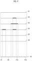
- FIG. 9 is a diagram illustrating the selection of a tomographic image of a tumor.
- FIG. 10 is a diagram illustrating the selection of a tomographic image of a spicula.
- FIG. 13 is a diagram illustrating the generation of a composite two-dimensional image.
- FIG. 15 is a diagram illustrating a composite two-dimensional image display screen.
- FIG. 16 is a flowchart illustrating a process performed in the first embodiment.
- FIG. 18 is a diagram illustrating band tomographic images.
- FIG. 20 is a diagram illustrating the selection of the band tomographic image for the tumor in a high frequency band.
- FIG. 21 is a diagram illustrating the selection of the band tomographic image for the spicula in the high frequency band.
- FIG. 22 is a diagram illustrating the selection of the band tomographic image for the calcification in the high frequency band.
- FIG. 23 is a diagram illustrating the generation of a composite band two-dimensional image in the medium-low frequency band.
- FIG. 24 is a diagram illustrating the generation of a composite band two-dimensional image in the high frequency band.
- FIG. 25 is a flowchart illustrating a process performed in the second embodiment.
- FIG. 28 is a diagram illustrating the generation of a second composite band two-dimensional image in the high frequency band for the spicula.
- FIG. 29 is a diagram illustrating the generation of a second composite band two-dimensional image in the high frequency band for the calcification.
- FIG. 30 is a diagram illustrating the generation of a composite two-dimensional image CG 0 in a third embodiment.
- FIG. 33 is a diagram illustrating the generation of a composite two-dimensional image in a fourth embodiment.
- FIG. 34 is a flowchart illustrating a process performed in the fourth embodiment.
- FIG. 35 is a diagram illustrating the generation of a composite band two-dimensional image in the high frequency band in a fifth embodiment.
- FIG. 36 is a diagram illustrating the generation of a composite band two-dimensional image in the high frequency band in a sixth embodiment.
- FIG. 37 is a diagram illustrating the generation of a second composite band two-dimensional image in the high frequency band for the tumor in the sixth embodiment.
- the image storage system 3 is a system that stores image data such as radiographic images and tomographic images captured by the mammography apparatus 1 .
- the image storage system 3 extracts an image corresponding to a request from, for example, the console 2 and the image processing device 4 from the stored images and transmits the image to a device that is the source of the request.
- a specific example of the image storage system 3 is a picture archiving and communication system (PACS).
- PACS picture archiving and communication system
- FIG. 5 is a diagram illustrating the acquisition of the projection images Gi.
- the radiation source 16 is moved to each of radiation source positions S 1 , S 2 , . . . , and Sn.
- the radiation source 16 is driven at each radiation source position to irradiate the breast M with radiation.
- the radiation detector 15 detects the radiation transmitted through the breast M to acquire projection images G 1 , G 2 , . . . , and Gn corresponding to the radiation source positions S 1 to Sn, respectively.
- the breast M is irradiated with the same dose of radiation.
- a radiation source position Sc is a radiation source position where an optical axis X 0 of the radiation emitted from the radiation source 16 is orthogonal to the detection surface 15 A of the radiation detector 15 . It is assumed that the radiation source position Sc is referred to as a reference radiation source position Sc.
- the console 2 directly transmits the generated tomographic images Dj to the image processing device 4 or transmits the generated tomographic images Dj to the image storage system 3 .
- the structure-of-interest detection unit 32 detects the structure of interest from the plurality of tomographic images Dj.
- a tumor, a spicula, and a calcification included in the breast M are detected as the structures of interest.
- FIG. 7 is a diagram illustrating the detection of the structures of interest.
- the tomographic image D 1 includes a calcification K 13 .
- the tomographic image D 2 includes a tumor K 21 .
- the tomographic image D 3 includes a tumor K 31 which is contiguous with the tumor K 21 in the tomographic image D 2 in the breast M and a spicula K 32 .
- the tomographic image D 4 includes a tumor K 41 a which is contiguous with the tumor K 21 in the tomographic image D 2 and the tumor K 31 in the tomographic image D 3 in the breast M, a tumor K 41 b which is present only in the tomographic image D 4 , and a spicula K 42 .
- the tomographic image D 5 includes a spicula K 52 .
- the tomographic image D 6 includes a calcification K 63 .
- the structure-of-interest detection unit 32 detects the structure of interest from the tomographic images Dj using a known computer-aided diagnosis (that is, CAD) algorithm.
- CAD computer-aided diagnosis
- the probability (likelihood) that the pixel in the tomographic images Dj will be the structure of interest is derived, and a pixel having a probability equal to or greater than a predetermined threshold value is detected as the structure of interest.
- the CAD algorithm is prepared for each type of structure of interest. In this embodiment, a CAD algorithm for detecting a tumor, a CAD algorithm for detecting a spicula, and a CAD algorithm for detecting a calcification are prepared.
- the detection of the structure of interest is not limited to the method using the CAD.
- the structure of interest may be detected from the tomographic images Dj by a filtering process using a filter for detecting the structure of interest, a detection model which has been subjected to machine learning by deep learning and the like to detect the structure of interest, and the like.
- the structure-of-interest detection unit 32 detects the tumor, the spicula, and the calcification as the structures of interest from the tomographic images D 1 to D 6 illustrated in FIG. 7 and derives a detection result R 1 of the tumor, a detection result R 2 of the spicula, and a detection result R 3 of the calcification as illustrated in FIG. 8 .
- the detection result R 1 of the tumor the tumor is detected in the tomographic images D 2 to D 4 .
- the detection result R 2 of the spicula the spicula is detected in the tomographic images D 3 to D 5 .
- the detection result R 3 of the calcification the calcification is detected in the tomographic images D 1 and D 6 .
- the selection unit 33 selects a tomographic image from the plurality of tomographic images Dj according to the type of the structure of interest in a region in which the structure of interest has been detected. Specifically, in the first embodiment, one tomographic image that best represents the structure of interest is selected for each pixel, which corresponds to a pixel of a composite two-dimensional image CG 0 , in the plurality of tomographic images Dj.
- FIG. 9 is a diagram illustrating the selection of the tomographic image of the tumor
- FIG. 10 is a diagram illustrating the selection of the tomographic image of the spicula
- FIG. 11 is a diagram illustrating the selection of the tomographic image of the calcification.
- the tomographic images are schematically illustrated one-dimensionally. Further, in FIGS. 9 to 11 , an index 40 for showing a correspondence relationship between the pixels of the tomographic image and the pixels of the composite two-dimensional image CG 0 is one-dimensionally illustrated. Furthermore, in the tomographic image including the structure of interest, the pixels of the detected structure of interest are shown to be thicker than the pixels other than the structure of interest. Further, the pixel of the tumor is painted black in FIG. 9 , the pixel of the spicula is painted white in FIG. 10 , and the pixel of the calcification is vertically hatched in FIG. 11 .
- pixels P 1 to P 15 corresponding to the pixels of the composite two-dimensional image CG 0 are illustrated. Further, in the index 40 , only the pixels P 1 , P 5 , P 10 , and P 15 are denoted by reference numerals. Furthermore, in the following description, the same figures as FIGS. 9 to 11 are illustrated in the same manner as FIGS. 9 to 11 .
- the selection unit 33 does not select any tomographic images for the pixels P 1 , P 4 to P 6 , and P 11 to P 15 .
- the selection unit 33 selects the tomographic image D 4 for the pixels P 2 and P 3 .
- the selection unit 33 selects the tomographic image D 3 for the pixels P 7 and P 10 .
- the tumor is detected in the tomographic images D 2 to D 4 .
- the tumor detected in the tomographic images D 3 is the largest, and the tomographic image D 3 among the tomographic images D 2 to D 4 best represents the tumor. Therefore, the selection unit 33 selects the tomographic image D 4 for the pixels P 8 and P 9 .
- a tomographic image including the tumor having the highest probability (likelihood) derived by the structure-of-interest detection unit 32 at the time of detection may be selected.
- the selection unit 33 does not select any tomographic images for the pixels P 1 , P 2 , P 7 , and P 12 to P 15 . Further, in the pixels P 3 , P 4 , and P 11 , the spicula is detected only in the tomographic image D 4 . Therefore, the selection unit 33 selects the tomographic image D 4 for the pixels P 3 , P 4 , and P 11 .
- the combination unit 34 uses the pixel value of the pixel P 11 of the tomographic image D 4 as the pixel value of the pixel P 11 of the composite two-dimensional image CG 0 . Since the tomographic image D 1 in which the calcification has been detected is selected for the pixel P 12 , the combination unit 34 sets the pixel value of the pixel P 12 of the tomographic image D 1 as the pixel value of the pixel P 12 of the composite two-dimensional image CG 0 .
- the combination unit 34 sets the pixel value of the pixel P 14 of the tomographic image D 6 as the pixel value of the pixel P 14 of the composite two-dimensional image CG 0 .
- FIG. 15 is a diagram illustrating a composite two-dimensional image display screen. As illustrated in FIG. 15 , the composite two-dimensional image CG 0 is displayed on a display screen 50 of the display 24 . In addition, the composite two-dimensional image CG 0 illustrated in FIG. 15 is generated from the tomographic images D 1 to D 6 illustrated in FIG. 7 . The composite two-dimensional image CG 0 illustrated in FIG.
- the 15 clearly includes the calcification K 13 included in the tomographic image D 1 , the tumor K 31 included in the tomographic image D 3 , the tumor K 41 b included in the tomographic image D 4 , the calcification K 63 included in the tomographic image D 6 , and the spiculae K 32 , K 42 , and K 52 included in the tomographic images D 3 to D 5 . Further, the illustration of the spiculae K 32 , K 42 , and K 52 is omitted.
- the spiculae K 32 , K 42 , and K 52 partially overlap the tumor K 31 , and the pixel values of the tumor K 31 are replaced with the pixel values of the spiculae K 42 and K 52 included in the tomographic images D 4 and D 5 .
- FIG. 16 is a flowchart illustrating the process performed in the first embodiment.
- the plurality of tomographic images Dj are acquired in advance and stored in the storage 23 .
- the process is started in a case in which the input device 25 receives a process start instruction from the operator, and the structure-of-interest detection unit 32 detects the structure of interest from each of the plurality of tomographic images Dj (Step ST 1 ).
- the selection unit 33 selects a tomographic image in which the structure of interest has been detected from the plurality of tomographic images Dj according to the type of the structure of interest (Step ST 2 ).
- the combination unit 34 generates the composite two-dimensional image CG 0 using the selected tomographic image (Step ST 3 ), and the display control unit 35 displays the composite two-dimensional image CG 0 on the display 24 (Step ST 4 ). Then, the process ends.
- a tomographic image is selected from the plurality of tomographic images Dj according to the type of the structure of interest, and the composite two-dimensional image CG 0 is generated using the selected tomographic image. Therefore, the composite two-dimensional image CG 0 is generated using a smaller number of tomographic images in the region of the structure of interest, as compared to a case in which the composite two-dimensional image is generated by weighting and averaging all of the tomographic images as in the method disclosed in U.S. Pat. No. 9,792,703B. As a result, in the composite two-dimensional image CG 0 , a fine structure of interest is not blurred.
- one tomographic image that best represents the structure of interest is selected for each of the corresponding pixels in a plurality of tomographic images. Therefore, it is possible to reduce the blurring of a fine structure of interest in the composite two-dimensional image CG 0 .
- one tomographic image that best represents the structure of interest is selected for each pixel, which corresponds to the pixel of the composite two-dimensional image CG 0 , in the plurality of tomographic images. Therefore, even in a case in which one structure of interest spreads in a direction in which the tomographic images are arranged, that is, in the depth direction of the breast M while two-dimensionally spreading in a direction orthogonal to the optical axis X 0 of radiation, a plurality of tomographic images are selected for the structure of interest.
- the combination unit 34 sets the added value of the pixel values of the pixels P 8 and P 9 of the band tomographic images DML 2 to DML 4 as the pixel values of the pixels P 8 and P 9 of the composite band two-dimensional image CGML 0 .
- a weighted added value, a weighted average value, or the like may be used instead of the added value.
- a weight for the band tomographic image DML 3 may be larger than those for the band tomographic images DML 2 and DML 4 .
- FIG. 25 is a flowchart illustrating the process performed in the second embodiment.
- the plurality of tomographic images Dj are acquired in advance and stored in the storage 23 .
- the process is started in a case in which the input device 25 receives a process start instruction from the operator, and the structure-of-interest detection unit 32 detects the structure of interest from the plurality of tomographic images Dj (Step ST 11 ).
- the frequency decomposition unit 36 performs frequency decomposition on each of the plurality of tomographic images Dj to derive a plurality of band tomographic images indicating frequency components in each of a plurality of frequency bands for each of the plurality of tomographic images Dj (Step ST 12 ).
- the selection unit 33 selects a band tomographic image corresponding to the tomographic image, in which the structure of interest has been detected, for each corresponding pixel in the plurality of band tomographic images from the plurality of band tomographic images according to the type of the structure of interest and the frequency band (Step ST 13 ).
- the combination unit 34 generates the composite band two-dimensional images CGML 0 and CGH 0 using the selected band tomographic images (Step ST 14 ) and performs frequency synthesis on the composite band two-dimensional images CGML 0 and CGH 0 to generate the composite two-dimensional image CG 0 (Step ST 15 ). Then, the display control unit 35 displays the composite two-dimensional image CG 0 on the display 24 (Step ST 16 ). Then, the process ends.
- the composite two-dimensional image CG 0 is generated using a plurality of selected band tomographic images, which makes it possible to reflect the state of the structure of interest in the depth direction in the composite two-dimensional image CG 0 .
- the combination unit 34 combines the plurality of tomographic images Dj to generate the first composite two-dimensional image CG 1 .
- the combination unit 34 For each of the structures of interest, the combination unit 34 generates a composite band two-dimensional image for each frequency band using the selected band tomographic image in the pixel of the band tomographic image corresponding to the structure of interest and performs frequency synthesis on the composite band two-dimensional images to generate second composite two-dimensional images CG 21 , CG 22 , and CG 23 for each of the structures of interest. Further, the combination unit 34 combines the second composite two-dimensional images CG 21 , CG 22 , and CG 23 for each of the structures of interest with the first composite two-dimensional image CG 1 to generate a composite two-dimensional image CG 0 .
- the combination unit 34 combines the plurality of tomographic images Dj to generate the first composite two-dimensional image CG 1 .
- the first composite two-dimensional image CG 1 is generated by, for example, adding and averaging the pixel values of the corresponding pixels in the plurality of tomographic images Dj.
- the combination unit 34 generates the second composite two-dimensional images CG 21 , CG 22 , and CG 23 according to the type of the structure of interest and the frequency band. That is, the second composite two-dimensional image CG 21 for the tumor, the second composite two-dimensional image CG 22 for the spicula, and the second composite two-dimensional image CG 23 for the calcification are generated. First, the generation of the second composite two-dimensional image CG 21 for the tumor will be described.
- the selection unit 33 selects the band tomographic image for each frequency band for each of the tumor, the spicula, and the calcification as in the second embodiment.
- the combination unit 34 generates a second composite band two-dimensional image CGML 21 using only the selected band tomographic image only in the pixel in which the tumor has been detected.
- the generation of the second composite band two-dimensional image CGML 21 in the medium-low frequency band MLf will be described.
- band tomographic images DML 2 to DML 4 are selected in the medium-low frequency band MLf.
- FIG. 26 is a diagram illustrating the generation of the second composite band two-dimensional image in the medium-low frequency band for the tumor.
- the combination unit 34 derives the added average value of the pixel values of the band tomographic images DML 1 to DML 6 and sets the added average value as the pixel values of the pixels P 1 , P 4 to P 6 , and P 11 to P 15 of the second composite band two-dimensional image CGML 21 in the medium-low frequency band MLf.
- the combination unit 34 sets the pixel values of the pixels P 2 and P 3 of the band tomographic image DML 4 as the pixel values of the pixels P 2 and P 3 of the second composite band two-dimensional image CGML 21 . Since the band tomographic image DML 3 is selected for the pixels P 7 and P 10 of the band tomographic images DMLj, the combination unit 34 sets the pixel values of the pixels P 7 and P 10 of the band tomographic image DML 3 as the pixel values of the pixels P 7 and P 10 of the second composite band two-dimensional image CGML 21 .
- the combination unit 34 sets the added value of the pixel values of the pixels P 8 and P 9 of the band tomographic images DML 2 to DML 4 as the pixel values of the pixels P 8 and P 9 of the second composite band two-dimensional image CGML 21 .
- a weighted added value, a weighted average value, or the like may be used instead of the added value.
- a weight for the band tomographic image DML 3 may be larger than those for the band tomographic images DML 2 and DML 4 .
- FIG. 27 is a diagram illustrating the generation of the second composite band two-dimensional image in the high frequency band for the tumor.
- the combination unit 34 derives the added average value of the pixel values of the band tomographic images DH 1 to DH 6 and sets the added average value as the pixel values of the pixels P 1 , P 4 to P 6 , and P 11 to P 15 of the second composite band two-dimensional image CGH 21 in the high frequency band Hf.
- the combination unit 34 sets the pixel values of the pixels P 2 and P 3 of the band tomographic image DH 4 as the pixel values of the pixels P 2 and P 3 of the second composite band two-dimensional image CGH 21 . Since the band tomographic image DH 3 is selected for the pixels P 7 to P 10 of the band tomographic images DHj, the combination unit 34 sets the pixel values of the pixels P 7 to P 10 of the band tomographic image DH 3 as the pixel values of the pixels P 7 to P 10 of the second composite band two-dimensional image CGH 21 .
- the combination unit 34 performs frequency synthesis on the second composite band two-dimensional image CGM 21 in the medium-low frequency band MLf and the second composite band two-dimensional image CGH 2 in the high frequency band Hf for the tumor to generate the second composite two-dimensional image CG 21 for the tumor.
- the combination unit 34 generates the second composite two-dimensional image CG 22 using only the selected band tomographic image only in the pixel in which the spicula has been detected.
- the structure of the spicula is included only in the band tomographic images DHj in the high frequency band Hf.
- FIG. 28 is a diagram illustrating the generation of the second composite band two-dimensional image in the high frequency band for the spicula.
- the combination unit 34 derives the added average value of the pixel values of the band tomographic images DH 1 to DH 6 and sets the added average value as the pixel values of the pixels P 1 , P 2 , P 7 , and P 12 to P 15 of a second composite band two-dimensional image CGH 22 in the high frequency band Hf.
- the combination unit 34 uses the pixel value of the pixel P 8 of the band tomographic image DH 3 as the pixel value of the pixel P 8 of the second composite band two-dimensional image CGH 22 .
- the combination unit 34 sequentially combines the second composite two-dimensional image CG 21 for the tumor, the second composite two-dimensional image CG 22 for the spicula, and the second composite two-dimensional image CG 23 for the calcification generated as described above with the first composite two-dimensional image CG 1 to generate the composite two-dimensional image CG 0 .
- FIG. 30 is a diagram illustrating the generation of the composite two-dimensional image CG 0 in the third embodiment. As illustrated in FIG. 30 , first, the combination unit 34 replaces the region of the tumor in the first composite two-dimensional image CG 1 with the region of the tumor in the second composite two-dimensional image CG 21 for the tumor to combine the second composite two-dimensional image CG 21 for the tumor with the first composite two-dimensional image CG 1 . As a result, an intermediate composite two-dimensional image CG 11 is generated.
- the combination unit 34 replaces the region of the calcification in the intermediate composite two-dimensional image CG 12 with the region of the calcification in the second composite two-dimensional image CG 23 for the calcification to combine the second composite two-dimensional image CG 23 for the calcification with the intermediate composite two-dimensional image CG 12 .
- the composite two-dimensional image CG 0 according to the third embodiment is generated.
- the frequency decomposition unit 36 performs frequency decomposition on each of the plurality of tomographic images Dj to derive a plurality of band tomographic images indicating frequency components in each of a plurality of frequency bands for each of the plurality of tomographic images Dj (Step ST 22 ).
- the selection unit 33 selects a band tomographic image corresponding to the tomographic image, in which the structure of interest has been detected, from the plurality of band tomographic images for each corresponding pixel of the plurality of band tomographic images according to the type of the structure of interest and the frequency band (Step ST 23 ).
- the combination unit 34 generates the first composite two-dimensional image CG 1 from the plurality of tomographic images Dj (Step ST 24 ).
- the process in Step ST 24 may be performed before each of the processes in Steps ST 21 to ST 23 or may be performed in parallel to these processes.
- the combination unit 34 generates the second composite two-dimensional images CG 21 , CG 22 , and CG 23 for the tumor, the spicula, and the calcification, respectively (Step ST 25 ).
- the generation of the first composite two-dimensional image CG 1 , the generation of the second composite two-dimensional image CG 21 for the tumor, and the generation of the second composite two-dimensional image CG 22 for the spicula are performed by the combination unit 34 in the same manner as in the second embodiment.
- the combination unit 34 sequentially combines the second composite two-dimensional images CG 21 and CG 22 for the tumor and the spicula with the first composite two-dimensional image CG 1 to generate the intermediate composite two-dimensional image CG 12 (Step ST 37 ). Then, the combination unit 34 combines the calcification regions 42 A and 42 B with the intermediate composite two-dimensional image CG 12 to generate the composite two-dimensional image CG 0 (Step ST 38 ). Further, the display control unit 35 displays the composite two-dimensional image CG 0 on the display 24 (Step ST 39 ). Then, the process ends.
- one tomographic image that best represents the tumor is selected for each pixel, which corresponds to the pixels of the composite two-dimensional image CG 0 , in the plurality of tomographic images Dj.
- the present disclosure is not limited thereto. All of the tomographic images including the tumor may be selected for each pixel, which corresponds to the pixels of the composite two-dimensional image CG 0 , in a plurality of tomographic images.
- this will be described as a fifth embodiment. First, the selection of the tomographic image in the fifth embodiment will be described with reference to FIG. 9 referred to in the first embodiment.
- the selection unit 33 does not select any tomographic images for the pixels P 1 , P 4 to P 6 , and P 11 to P 15 . Further, in the pixels P 2 and P 3 , the tumor is detected only in the tomographic image D 4 . Therefore, the selection unit 33 selects the tomographic image D 4 for the pixels P 2 and P 3 . In the pixels P 7 and P 10 , the tumor is detected only in the tomographic image D 3 . Therefore, the selection unit 33 selects the tomographic image D 3 for the pixels P 7 and P 10 .
- one tomographic image that best represents the spicula is selected for each pixel, which corresponds to the pixels of the composite two-dimensional image CG 0 , in the plurality of tomographic images Dj.
- the spicula connected in adjacent tomographic images is selected.
- the present disclosure is not limited thereto.
- only one tomographic image that best represents the spicula may be selected for each pixel, which corresponds to the pixels of the composite two-dimensional image CG 0 , in the plurality of tomographic images Dj.
- the selection of the tomographic image for the spicula in the fifth embodiment will be described with reference to FIG. 10 referred to in the first embodiment.
- the selection unit 33 does not select any tomographic images for the pixels P 1 , P 2 , P 7 , and P 12 to P 15 .
- the selection unit 33 selects the tomographic image D 4 for the pixels P 3 , P 4 , and P 11 .
- the spicula is detected in the tomographic images D 4 and D 5 .
- the spiculae in the pixels P 5 and P 10 are connected between the tomographic images D 4 and D 5 .
- the selection unit 33 selects the tomographic image D 4 for the pixels P 5 and P 10 .
- a tomographic image including the spicula having the highest probability (likelihood) derived by the structure-of-interest detection unit 32 at the time of detection may be selected.
- the spicula is detected only in the tomographic image D 5 .
- the spicula detected in the pixels P 6 and P 9 of the tomographic image D 5 is connected to the spicula detected in the pixels P 5 and P 10 of the tomographic image D 4 . Therefore, in the fifth embodiment, none of the tomographic images are selected for the pixels P 6 and P 9 .
- the spicula is detected in the tomographic image D 3 .
- the spicula detected in the pixel P 8 of the tomographic image D 3 is not connected to the spicula detected in any of the tomographic images. Therefore, the selection unit 33 selects the tomographic image D 3 for the pixel P 8 .
- the combination unit 34 generates the composite two-dimensional image CG 0 as follows.
- FIG. 35 is a diagram illustrating the generation of the composite two-dimensional image in the fifth embodiment.
- the combination unit 34 derives the added average value of the pixel values of the tomographic images D 1 to D 6 and sets the added average value as the pixel values of the pixels P 1 , P 13 , and P 15 of the composite two-dimensional image CG 0 .
- all of the tomographic images correspond to the predetermined tomographic images according to the present disclosure.
- the combination unit 34 sets the pixel value of the pixel P 2 of the tomographic image D 4 as the pixel value of the pixel P 2 of the composite two-dimensional image CG 0 . Since the tomographic image D 4 in which the tumor and the spicula have been detected is selected for the pixel P 3 , the combination unit 34 sets the pixel value of the pixel P 3 of the tomographic image D 4 as the pixel value of the pixel P 3 of the composite two-dimensional image CG 0 .
- the combination unit 34 sets the pixel values of the pixels P 4 and P 5 of the tomographic image D 4 as the pixel values of the pixels P 4 and P 5 of the composite two-dimensional image CG 0 .
- the combination unit 34 derives the added average value of the pixel values of the tomographic images D 1 to D 6 and sets the added average value as the pixel value of the pixel P 6 of the composite two-dimensional image CG 0 . Since the tomographic image D 3 in which the tumor has been detected is selected for the pixel P 7 , the combination unit 34 sets the pixel value of the pixel P 7 of the tomographic image D 3 as the pixel value of the pixel P 7 of the composite two-dimensional image CG 0 .
- the combination unit 34 sets the pixel value of the pixel P 8 of the tomographic image D 3 in which the spicula has been detected as the pixel value of the pixel P 8 of the composite two-dimensional image CG 0 .
- the spicula is detected in the tomographic image D 5 .
- the tomographic image D 5 is not selected, and the tomographic images D 2 to D 4 in which the tumor has been detected are selected.
- the combination unit 34 sets the added value of the pixel values of the pixels P 9 of the tomographic images D 2 to D 4 as the pixel value of the pixel P 9 of the composite two-dimensional image CG 0 .
- a weighted added value, a weighted average value, or the like may be used instead of the added value.
- a weight for the tomographic image D 3 may be larger than those for the tomographic images D 2 and D 4 .
- the combination unit 34 sets the pixel value of the pixel P 10 of the tomographic image D 4 in which the spicula has been detected as the pixel value of the pixel P 10 of the composite two-dimensional image CG 0 .
- the combination unit 34 uses the pixel value of the pixel P 11 of the tomographic image D 4 as the pixel value of the pixel P 11 of the composite two-dimensional image CG 0 . Since the tomographic image D 1 in which the calcification has been detected is selected for the pixel P 12 , the combination unit 34 sets the pixel value of the pixel P 12 of the tomographic image D 1 as the pixel value of the pixel P 12 of the composite two-dimensional image CG 0 .
- the combination unit 34 sets the pixel value of the pixel P 14 of the tomographic image D 6 as the pixel value of the pixel P 14 of the composite two-dimensional image CG 0 .
- the combination unit 34 generates the composite two-dimensional image CG 0 by setting the pixel value of the pixel, in which the structure of interest has been detected, in the composite two-dimensional image CG 0 as the pixel value of the selected tomographic image.
- the tomographic image related to the spicula may be selected as in the first embodiment.
- the tomographic image D 5 is selected for the pixels P 6 and P 9 . Therefore, the pixel values of the pixels P 6 and P 9 of the composite two-dimensional image CG 0 are the pixel values of the pixels P 6 and P 9 of the tomographic image D 5 .
- the selection of the band tomographic image is not limited thereto.
- all of the band tomographic images including the tumor may be selected for each pixel, which corresponds to the pixels of the composite two-dimensional image CG 0 , in the plurality of band tomographic images.
- this will be described as a sixth embodiment.
- the combination unit 34 In a case in which the band tomographic image is selected as in the sixth embodiment and the process according to the second embodiment is performed, the combination unit 34 generates the composite band two-dimensional image CGML 0 in the medium-low frequency band MLf as in the second embodiment. Meanwhile, in the sixth embodiment, the band tomographic image is not selected in the high frequency band Hf for the tumor. Therefore, the band tomographic images DH 2 and DH 3 - 1 are not selected even for the pixels P 2 and P 7 illustrated in FIG. 24 .
Landscapes
- Engineering & Computer Science (AREA)
- Physics & Mathematics (AREA)
- Health & Medical Sciences (AREA)
- General Physics & Mathematics (AREA)
- Theoretical Computer Science (AREA)
- Life Sciences & Earth Sciences (AREA)
- Medical Informatics (AREA)
- Computer Vision & Pattern Recognition (AREA)
- General Health & Medical Sciences (AREA)
- Nuclear Medicine, Radiotherapy & Molecular Imaging (AREA)
- Radiology & Medical Imaging (AREA)
- Multimedia (AREA)
- Animal Behavior & Ethology (AREA)
- Molecular Biology (AREA)
- High Energy & Nuclear Physics (AREA)
- Optics & Photonics (AREA)
- Pathology (AREA)
- Biomedical Technology (AREA)
- Heart & Thoracic Surgery (AREA)
- Biophysics (AREA)
- Surgery (AREA)
- Veterinary Medicine (AREA)
- Public Health (AREA)
- Quality & Reliability (AREA)
- Dentistry (AREA)
- Oral & Maxillofacial Surgery (AREA)
- Apparatus For Radiation Diagnosis (AREA)
Abstract
Description
Claims (18)
Applications Claiming Priority (3)
| Application Number | Priority Date | Filing Date | Title |
|---|---|---|---|
| JP2020047343 | 2020-03-18 | ||
| JP2020-047343 | 2020-03-18 | ||
| PCT/JP2021/004849 WO2021186957A1 (en) | 2020-03-18 | 2021-02-09 | Image processing device, method, and program |
Related Parent Applications (1)
| Application Number | Title | Priority Date | Filing Date |
|---|---|---|---|
| PCT/JP2021/004849 Continuation WO2021186957A1 (en) | 2020-03-18 | 2021-02-09 | Image processing device, method, and program |
Publications (2)
| Publication Number | Publication Date |
|---|---|
| US20220398726A1 US20220398726A1 (en) | 2022-12-15 |
| US12272055B2 true US12272055B2 (en) | 2025-04-08 |
Family
ID=77768071
Family Applications (1)
| Application Number | Title | Priority Date | Filing Date |
|---|---|---|---|
| US17/821,799 Active 2042-02-03 US12272055B2 (en) | 2020-03-18 | 2022-08-24 | Image processing device, image processing method, and image processing program |
Country Status (4)
| Country | Link |
|---|---|
| US (1) | US12272055B2 (en) |
| EP (1) | EP4122397B1 (en) |
| JP (1) | JP7446410B2 (en) |
| WO (1) | WO2021186957A1 (en) |
Families Citing this family (1)
| Publication number | Priority date | Publication date | Assignee | Title |
|---|---|---|---|---|
| JPWO2023139971A1 (en) * | 2022-01-19 | 2023-07-27 |
Citations (26)
| Publication number | Priority date | Publication date | Assignee | Title |
|---|---|---|---|---|
| JPH08294485A (en) | 1995-02-28 | 1996-11-12 | Toshiba Corp | Image display system and image display method using the system |
| US20040101095A1 (en) | 2002-11-27 | 2004-05-27 | Hologic Inc. | Full field mammography with tissue exposure control, tomosynthesis, and dynamic field of view processing |
| US20050113681A1 (en) | 2002-11-27 | 2005-05-26 | Defreitas Kenneth F. | X-ray mammography with tomosynthesis |
| US20060098855A1 (en) | 2002-11-27 | 2006-05-11 | Gkanatsios Nikolaos A | Image handling and display in X-ray mammography and tomosynthesis |
| US20080019581A1 (en) | 2002-11-27 | 2008-01-24 | Gkanatsios Nikolaos A | Image Handling and display in X-ray mammography and tomosynthesis |
| US20080130979A1 (en) | 2004-11-15 | 2008-06-05 | Baorui Ren | Matching Geometry Generation and Display of Mammograms and Tomosynthesis Images |
| US20090003519A1 (en) | 2004-11-26 | 2009-01-01 | Kenneth Defreitas | Integrated Multi-Mode Mammography/Tomosynthesis X-Ray System And Method |
| US20090123052A1 (en) | 2002-11-27 | 2009-05-14 | Chris Ruth | System and Method for Generating a 2D Image from a Tomosynthesis Data Set |
| US20090213987A1 (en) | 2003-11-26 | 2009-08-27 | Jay Stein | System and Method for Low Dose Tomosynthesis |
| US20090268865A1 (en) | 2003-11-26 | 2009-10-29 | Baorui Ren | X-ray imaging with X-ray markers that provide adjunct information but preserve image quality |
| US20100135558A1 (en) | 2002-11-27 | 2010-06-03 | Chris Ruth | System and Method for Generating a 2D Image from a Tomosynthesis Data Set |
| WO2013027138A1 (en) * | 2011-08-19 | 2013-02-28 | Koninklijke Philips Electronics N.V. | Frequency dependent combination of x-ray images of different modalities |
| US20130272494A1 (en) | 2002-11-27 | 2013-10-17 | Hologic, Inc. | X-ray mammography with tomosynthesis |
| US20140327702A1 (en) * | 2005-11-10 | 2014-11-06 | Hologic, Inc | System and method for generating a 2d image using mammography and/or tomosynthesis image data |
| US8983156B2 (en) | 2012-11-23 | 2015-03-17 | Icad, Inc. | System and method for improving workflow efficiences in reading tomosynthesis medical image data |
| US20160140749A1 (en) | 2013-06-28 | 2016-05-19 | Koninklijke Philips N.V. | Methods for generation of edge=preserving synthetic mammograms from tomosynthesis data |
| WO2016078958A1 (en) * | 2014-11-20 | 2016-05-26 | Koninklijke Philips N.V. | Method for generation of synthetic mammograms from tomosynthesis data |
| US20160367210A1 (en) | 2014-02-28 | 2016-12-22 | Hologic, Inc. | System and method for generating and displaying tomosynthesis image slabs |
| US20170011534A1 (en) * | 2015-07-06 | 2017-01-12 | Maria Jimena Costa | Generating a synthetic two-dimensional mammogram |
| US20170071554A1 (en) | 2015-09-16 | 2017-03-16 | Fujifilm Corporation | Tomographic image generation device, method and recording medium |
| US20170323436A1 (en) | 2016-05-06 | 2017-11-09 | L-3 Communications Security & Detection Systems, Inc. | Systems and methods for generating projection images |
| JP2018029746A (en) | 2016-08-24 | 2018-03-01 | 富士フイルム株式会社 | Image processing device, method, and program |
| US20180068442A1 (en) * | 2016-09-08 | 2018-03-08 | Fujifilm Corporation | Image processing apparatus, image processing method, and image processing program |
| WO2018183549A1 (en) | 2017-03-30 | 2018-10-04 | Hologic, Inc. | System and method for synthesizing low-dimensional image data from high-dimensional image data using an object grid enhancement |
| US20190043456A1 (en) | 2011-11-27 | 2019-02-07 | Hologic, Inc. | System and method for generating a 2d image using mammography and/or tomosynthesis image data |
| US20190076101A1 (en) * | 2017-09-13 | 2019-03-14 | The University Of Chicago | Multiresolution iterative reconstruction for region of interest imaging in x-ray cone-beam computed tomography |
-
2021
- 2021-02-09 WO PCT/JP2021/004849 patent/WO2021186957A1/en not_active Ceased
- 2021-02-09 JP JP2022508133A patent/JP7446410B2/en active Active
- 2021-02-09 EP EP21772300.6A patent/EP4122397B1/en active Active
-
2022
- 2022-08-24 US US17/821,799 patent/US12272055B2/en active Active
Patent Citations (77)
| Publication number | Priority date | Publication date | Assignee | Title |
|---|---|---|---|---|
| JPH08294485A (en) | 1995-02-28 | 1996-11-12 | Toshiba Corp | Image display system and image display method using the system |
| US20090010384A1 (en) | 2002-11-27 | 2009-01-08 | Hologic, Inc. | Full field mammography with tissue exposure control, tomosynthesis, and dynamic field of view processing |
| US20110135185A1 (en) | 2002-11-27 | 2011-06-09 | Hologic, Inc. | Image handling and display in x-ray mammography and tomosynthesis |
| US20060098855A1 (en) | 2002-11-27 | 2006-05-11 | Gkanatsios Nikolaos A | Image handling and display in X-ray mammography and tomosynthesis |
| US20070030949A1 (en) | 2002-11-27 | 2007-02-08 | Zhenxue Jing | Full field mammography with tissue exposure control, tomosynthesis, and dynamic field of view processing |
| US20080019581A1 (en) | 2002-11-27 | 2008-01-24 | Gkanatsios Nikolaos A | Image Handling and display in X-ray mammography and tomosynthesis |
| US20200348835A1 (en) | 2002-11-27 | 2020-11-05 | Hologic, Inc. | Image handling and display in x-ray mammography and tomosynthesis |
| US20200012417A1 (en) | 2002-11-27 | 2020-01-09 | Hologic, Inc. | Image handling and display in x-ray mammography and tomosynthesis |
| US20150160848A1 (en) | 2002-11-27 | 2015-06-11 | Hologic, Inc. | Image handling and display in x-ray mammography and tomosynthesis |
| US20110069808A1 (en) | 2002-11-27 | 2011-03-24 | Hologic, Inc. | X-ray mammography with tomosynthesis |
| US20090141859A1 (en) | 2002-11-27 | 2009-06-04 | Hologic, Inc. | Image Handling and Display in X-Ray Mammography and Tomosynthesis |
| US20190095087A1 (en) | 2002-11-27 | 2019-03-28 | Hologic, Inc. | Image handling and display in x-ray mammography and tomosynthesis |
| US20190053776A1 (en) | 2002-11-27 | 2019-02-21 | Hologic, Inc. | System and method for generating a 2d image from a tomosynthesis data set |
| US20090296882A1 (en) | 2002-11-27 | 2009-12-03 | Hologic, Inc. | Image Handling And Display In X-Ray Mammography And Tomosynthess |
| US20100135456A1 (en) | 2002-11-27 | 2010-06-03 | Hologic, Inc. | Full Field Mammography With Tissue Exposure Control, Tomosynthesis, and Dynamic Field of View Processing |
| US20050113681A1 (en) | 2002-11-27 | 2005-05-26 | Defreitas Kenneth F. | X-ray mammography with tomosynthesis |
| US20100135558A1 (en) | 2002-11-27 | 2010-06-03 | Chris Ruth | System and Method for Generating a 2D Image from a Tomosynthesis Data Set |
| US20090123052A1 (en) | 2002-11-27 | 2009-05-14 | Chris Ruth | System and Method for Generating a 2D Image from a Tomosynthesis Data Set |
| US20040101095A1 (en) | 2002-11-27 | 2004-05-27 | Hologic Inc. | Full field mammography with tissue exposure control, tomosynthesis, and dynamic field of view processing |
| US20110216879A1 (en) | 2002-11-27 | 2011-09-08 | Hologic, Inc. | Full Field Mammography With Tissue Exposure Control, Tomosynthesis, And Dynamic Field Of View Processing |
| US20180188937A1 (en) | 2002-11-27 | 2018-07-05 | Hologic, Inc. | Image handling and display in x-ray mammography and tomosynthesis |
| US20130028374A1 (en) | 2002-11-27 | 2013-01-31 | Hologic, Inc. | Image handling and display in x-ray mammography and tomosynthesis |
| US20180177476A1 (en) | 2002-11-27 | 2018-06-28 | Hologic, Inc. | Full field mammography with tissue exposure control, tomosynthesis, and dynamic field of view processing |
| US20130223591A1 (en) | 2002-11-27 | 2013-08-29 | Hologic, Inc. | Full field mammography with tissue exposure control, tomosynthesis, and dynamic field of view processing |
| US20130272494A1 (en) | 2002-11-27 | 2013-10-17 | Hologic, Inc. | X-ray mammography with tomosynthesis |
| US20140044230A1 (en) | 2002-11-27 | 2014-02-13 | Hologic, Inc. | System and Method for Low Dose Tomosynthesis |
| US20140086471A1 (en) | 2002-11-27 | 2014-03-27 | Hologic, Inc. | System and Method for Generating A 2D Image from a Tomosynthesis Data Set |
| US20180055470A1 (en) | 2002-11-27 | 2018-03-01 | Hologic, Inc. | System and method for generating a 2d image from a tomosynthesis data set |
| US20170024113A1 (en) | 2002-11-27 | 2017-01-26 | Hologic, Inc. | Image handling and display in x-ray mammography and tomosynthesis |
| US20160220210A1 (en) | 2002-11-27 | 2016-08-04 | Hologic, Inc. | System and method for generating a 2d image from a tomosynthesis data set |
| US20150310611A1 (en) | 2002-11-27 | 2015-10-29 | Hologic, Inc. | Image handling and display in x-ray mammography and tomosynthesis |
| US20140376690A1 (en) | 2002-11-27 | 2014-12-25 | Hologic, Inc. | Full field mammography with tissue exposure control, tomosynthesis, and dynamic field of view processing |
| US20150182181A1 (en) | 2002-11-27 | 2015-07-02 | Hologic, Inc. | System and Method for Generating A 2D Image from a Tomosynthesis Data Set |
| US20180289347A1 (en) | 2003-11-26 | 2018-10-11 | Hologic, Inc. | X-ray mammography with tomosynthesis |
| US20170135650A1 (en) | 2003-11-26 | 2017-05-18 | Hologic, Inc. | System and method for low dose tomosynthesis |
| US20180344276A1 (en) | 2003-11-26 | 2018-12-06 | Hologic, Inc. | X-ray mammography with tomosynthesis |
| US20090268865A1 (en) | 2003-11-26 | 2009-10-29 | Baorui Ren | X-ray imaging with X-ray markers that provide adjunct information but preserve image quality |
| US20090213987A1 (en) | 2003-11-26 | 2009-08-27 | Jay Stein | System and Method for Low Dose Tomosynthesis |
| US20220071582A1 (en) | 2003-11-26 | 2022-03-10 | Hologic, Inc. | X-ray mammography with tomosynthesis |
| US20200022663A1 (en) | 2003-11-26 | 2020-01-23 | Hologic, Inc. | X-ray imaging with x-ray markers that provide adjunct information but preserve image quality |
| US20140301529A1 (en) | 2003-11-26 | 2014-10-09 | Hologic, Inc. | X-ray imaging with x-ray markers that provide adjunct information but preserve image quality |
| US20210204894A1 (en) | 2003-11-26 | 2021-07-08 | Hologic, Inc. | X-ray imaging with x-ray markers that provide adjunct information but preserve image quality |
| US20180137385A1 (en) | 2004-11-15 | 2018-05-17 | Hologic, Inc. | Matching geometry generation and display of mammograms and tomosynthesis images |
| US20140232752A1 (en) | 2004-11-15 | 2014-08-21 | Hologic, Inc. | Matching geometry generation and display of mammograms and tomosynthesis |
| US20080130979A1 (en) | 2004-11-15 | 2008-06-05 | Baorui Ren | Matching Geometry Generation and Display of Mammograms and Tomosynthesis Images |
| US20100195882A1 (en) | 2004-11-15 | 2010-08-05 | Hologic, Inc. | Matching Geometry Generation And Display Of Mammograms And Tomosynthesis Images |
| US20150317538A1 (en) | 2004-11-15 | 2015-11-05 | Hologic, Inc. | Matching geometry generation and display of mammograpms and tomosynthesis |
| US20120195484A1 (en) | 2004-11-15 | 2012-08-02 | Hologic, Inc. | Matching geometry generation and display of mammograms and tomosynthesis images |
| US20190325255A1 (en) | 2004-11-15 | 2019-10-24 | Hologic, Inc. | Matching geometry generation and display of mammograms and tomosynthesis images |
| US20210128087A1 (en) | 2004-11-26 | 2021-05-06 | Hologic, Inc. | Integrated multi-mode mammography/tomosynthesis x-ray system and method |
| US20090003519A1 (en) | 2004-11-26 | 2009-01-01 | Kenneth Defreitas | Integrated Multi-Mode Mammography/Tomosynthesis X-Ray System And Method |
| US20140327702A1 (en) * | 2005-11-10 | 2014-11-06 | Hologic, Inc | System and method for generating a 2d image using mammography and/or tomosynthesis image data |
| JP2014128716A (en) | 2008-11-21 | 2014-07-10 | Hologic Inc | System and method for generating 2d image from tomosynthesis dataset |
| WO2013027138A1 (en) * | 2011-08-19 | 2013-02-28 | Koninklijke Philips Electronics N.V. | Frequency dependent combination of x-ray images of different modalities |
| US20220013089A1 (en) | 2011-11-27 | 2022-01-13 | Hologic, Inc. | System and method for generating a 2d image using mammography and/or tomosynthesis image data |
| US20200258479A1 (en) | 2011-11-27 | 2020-08-13 | Hologic, Inc. | System and method for generating a 2d image using mammography and/or tomosynthesis image data |
| US20190043456A1 (en) | 2011-11-27 | 2019-02-07 | Hologic, Inc. | System and method for generating a 2d image using mammography and/or tomosynthesis image data |
| US8983156B2 (en) | 2012-11-23 | 2015-03-17 | Icad, Inc. | System and method for improving workflow efficiences in reading tomosynthesis medical image data |
| US20160140749A1 (en) | 2013-06-28 | 2016-05-19 | Koninklijke Philips N.V. | Methods for generation of edge=preserving synthetic mammograms from tomosynthesis data |
| JP2016522071A (en) | 2013-06-28 | 2016-07-28 | コーニンクレッカ フィリップス エヌ ヴェKoninklijke Philips N.V. | A method for generating edge-preserving synthetic mammograms from tomosynthesis data |
| US20190125286A1 (en) | 2014-02-28 | 2019-05-02 | Hologic, Inc. | System and method for generating and displaying tomosynthesis image slabs |
| US20200253573A1 (en) | 2014-02-28 | 2020-08-13 | Hologic, Inc. | System and method for generating and displaying tomosynthesis image slabs |
| US20160367210A1 (en) | 2014-02-28 | 2016-12-22 | Hologic, Inc. | System and method for generating and displaying tomosynthesis image slabs |
| JP2019122817A (en) | 2014-02-28 | 2019-07-25 | ホロジック, インコーポレイテッドHologic, Inc. | System and method for generating and displaying tomo-synthesis image slab |
| WO2016078958A1 (en) * | 2014-11-20 | 2016-05-26 | Koninklijke Philips N.V. | Method for generation of synthetic mammograms from tomosynthesis data |
| US9792703B2 (en) | 2015-07-06 | 2017-10-17 | Siemens Healthcare Gmbh | Generating a synthetic two-dimensional mammogram |
| US20170011534A1 (en) * | 2015-07-06 | 2017-01-12 | Maria Jimena Costa | Generating a synthetic two-dimensional mammogram |
| US20170071554A1 (en) | 2015-09-16 | 2017-03-16 | Fujifilm Corporation | Tomographic image generation device, method and recording medium |
| JP2017055973A (en) | 2015-09-16 | 2017-03-23 | 富士フイルム株式会社 | Tomographic image generating apparatus, method and program |
| US20170323436A1 (en) | 2016-05-06 | 2017-11-09 | L-3 Communications Security & Detection Systems, Inc. | Systems and methods for generating projection images |
| WO2017192160A1 (en) | 2016-05-06 | 2017-11-09 | L-3 Communications Security & Detection Systems, Inc. | Systems and methods for generating projection images |
| US20180055459A1 (en) * | 2016-08-24 | 2018-03-01 | Fujifilm Corporation | Image processing apparatus, method, and program |
| JP2018029746A (en) | 2016-08-24 | 2018-03-01 | 富士フイルム株式会社 | Image processing device, method, and program |
| US20180068442A1 (en) * | 2016-09-08 | 2018-03-08 | Fujifilm Corporation | Image processing apparatus, image processing method, and image processing program |
| WO2018183549A1 (en) | 2017-03-30 | 2018-10-04 | Hologic, Inc. | System and method for synthesizing low-dimensional image data from high-dimensional image data using an object grid enhancement |
| US20210118199A1 (en) | 2017-03-30 | 2021-04-22 | Hologic, Inc. | System and method for synthesizing low-dimensional image data from high-dimensional image data using an object grid enhancement |
| US20190076101A1 (en) * | 2017-09-13 | 2019-03-14 | The University Of Chicago | Multiresolution iterative reconstruction for region of interest imaging in x-ray cone-beam computed tomography |
Non-Patent Citations (4)
| Title |
|---|
| English language translation of the following: Office action dated Oct. 3, 2023 from the JPO in a Japanese patent application No. 2022-508133 corresponding to the instant patent application. |
| Extended European Search Report dated Jul. 20, 2023, issued in corresponding EP Patent Application No. 21772300.6. |
| International Search Report issued in International Application No. PCT/JP2021/004849 on Apr. 27, 2021. |
| Written Opinion of the ISA issued in International Application No. PCT/JP2021/004849 on Apr. 27, 2021. |
Also Published As
| Publication number | Publication date |
|---|---|
| EP4122397A1 (en) | 2023-01-25 |
| EP4122397B1 (en) | 2024-11-13 |
| US20220398726A1 (en) | 2022-12-15 |
| EP4122397A4 (en) | 2023-08-23 |
| JP7446410B2 (en) | 2024-03-08 |
| WO2021186957A1 (en) | 2021-09-23 |
| JPWO2021186957A1 (en) | 2021-09-23 |
Similar Documents
| Publication | Publication Date | Title |
|---|---|---|
| US11587215B2 (en) | Image processing device, image processing method, image processing program, image display device, image display method, and image display program | |
| US12417565B2 (en) | Image generation device, image generation program, learning device, learning program, image processing device, and image processing program | |
| US20230206397A1 (en) | Image processing device, method for operating image processing device, and program for operating image processing device | |
| US12488423B2 (en) | Image processing device, method for operating image processing device, and program for operating image processing device | |
| US12272055B2 (en) | Image processing device, image processing method, and image processing program | |
| US12307664B2 (en) | Image processing device, image processing method, and image processing program | |
| US12327352B2 (en) | Image setting device, image setting method, and image setting program | |
| US12536649B2 (en) | Image processing device, image processing method, and image processing program for facilitating image diagnosis using mammography apparatus to generate composite two-dimensional tomographic image using selected tomographic image slices corresponding to detected spicula regions | |
| US20220343500A1 (en) | Image setting device, image setting method, and image setting program | |
| US20230146430A1 (en) | Image processing device, image processing method, and image processing program | |
| US12419590B2 (en) | Image processing device, image processing method, and image processing program | |
| US12112479B2 (en) | Image processing device, image processing method, and image processing program | |
| US11224397B2 (en) | Imaging control device, imaging control method, and imaging control program | |
| US20220343501A1 (en) | Image setting device, image setting method, and image setting program | |
| JP2025040874A (en) | IMAGE PROCESSING APPARATUS, RADIOLOGICAL IMAGE CAPTURE SYSTEM AND PROGRAM | |
| JP2025051943A (en) | Image processing apparatus, radiation image capturing system and program |
Legal Events
| Date | Code | Title | Description |
|---|---|---|---|
| FEPP | Fee payment procedure |
Free format text: ENTITY STATUS SET TO UNDISCOUNTED (ORIGINAL EVENT CODE: BIG.); ENTITY STATUS OF PATENT OWNER: LARGE ENTITY |
|
| AS | Assignment |
Owner name: FUJIFILM CORPORATION, JAPAN Free format text: ASSIGNMENT OF ASSIGNORS INTEREST;ASSIGNOR:KOIKE, TAKAFUMI;REEL/FRAME:060934/0104 Effective date: 20220710 |
|
| STPP | Information on status: patent application and granting procedure in general |
Free format text: DOCKETED NEW CASE - READY FOR EXAMINATION |
|
| STPP | Information on status: patent application and granting procedure in general |
Free format text: NON FINAL ACTION MAILED |
|
| STPP | Information on status: patent application and granting procedure in general |
Free format text: RESPONSE TO NON-FINAL OFFICE ACTION ENTERED AND FORWARDED TO EXAMINER |
|
| STPP | Information on status: patent application and granting procedure in general |
Free format text: NOTICE OF ALLOWANCE MAILED -- APPLICATION RECEIVED IN OFFICE OF PUBLICATIONS |
|
| STPP | Information on status: patent application and granting procedure in general |
Free format text: AWAITING TC RESP., ISSUE FEE NOT PAID |
|
| STPP | Information on status: patent application and granting procedure in general |
Free format text: NOTICE OF ALLOWANCE MAILED -- APPLICATION RECEIVED IN OFFICE OF PUBLICATIONS |
|
| STPP | Information on status: patent application and granting procedure in general |
Free format text: PUBLICATIONS -- ISSUE FEE PAYMENT RECEIVED |
|
| STPP | Information on status: patent application and granting procedure in general |
Free format text: PUBLICATIONS -- ISSUE FEE PAYMENT VERIFIED |
|
| STCF | Information on status: patent grant |
Free format text: PATENTED CASE |