US12270540B2 - Deep cleaning alignment equipment - Google Patents
Deep cleaning alignment equipment Download PDFInfo
- Publication number
- US12270540B2 US12270540B2 US17/729,133 US202217729133A US12270540B2 US 12270540 B2 US12270540 B2 US 12270540B2 US 202217729133 A US202217729133 A US 202217729133A US 12270540 B2 US12270540 B2 US 12270540B2
- Authority
- US
- United States
- Prior art keywords
- wedge
- tubes
- deep cleaning
- alignment equipment
- elongate
- Prior art date
- Legal status (The legal status is an assumption and is not a legal conclusion. Google has not performed a legal analysis and makes no representation as to the accuracy of the status listed.)
- Active, expires
Links
Images


Classifications
-
- B—PERFORMING OPERATIONS; TRANSPORTING
- B08—CLEANING
- B08B—CLEANING IN GENERAL; PREVENTION OF FOULING IN GENERAL
- B08B13/00—Accessories or details of general applicability for machines or apparatus for cleaning
-
- B—PERFORMING OPERATIONS; TRANSPORTING
- B08—CLEANING
- B08B—CLEANING IN GENERAL; PREVENTION OF FOULING IN GENERAL
- B08B3/00—Cleaning by methods involving the use or presence of liquid or steam
- B08B3/02—Cleaning by the force of jets or sprays
-
- B—PERFORMING OPERATIONS; TRANSPORTING
- B08—CLEANING
- B08B—CLEANING IN GENERAL; PREVENTION OF FOULING IN GENERAL
- B08B3/00—Cleaning by methods involving the use or presence of liquid or steam
- B08B3/02—Cleaning by the force of jets or sprays
- B08B3/026—Cleaning by making use of hand-held spray guns; Fluid preparations therefor
-
- B—PERFORMING OPERATIONS; TRANSPORTING
- B08—CLEANING
- B08B—CLEANING IN GENERAL; PREVENTION OF FOULING IN GENERAL
- B08B5/00—Cleaning by methods involving the use of air flow or gas flow
- B08B5/02—Cleaning by the force of jets, e.g. blowing-out cavities
-
- B—PERFORMING OPERATIONS; TRANSPORTING
- B08—CLEANING
- B08B—CLEANING IN GENERAL; PREVENTION OF FOULING IN GENERAL
- B08B7/00—Cleaning by methods not provided for in a single other subclass or a single group in this subclass
-
- B—PERFORMING OPERATIONS; TRANSPORTING
- B08—CLEANING
- B08B—CLEANING IN GENERAL; PREVENTION OF FOULING IN GENERAL
- B08B9/00—Cleaning hollow articles by methods or apparatus specially adapted thereto
- B08B9/02—Cleaning pipes or tubes or systems of pipes or tubes
- B08B9/023—Cleaning the external surfaces
-
- B—PERFORMING OPERATIONS; TRANSPORTING
- B24—GRINDING; POLISHING
- B24C—ABRASIVE OR RELATED BLASTING WITH PARTICULATE MATERIAL
- B24C1/00—Methods for use of abrasive blasting for producing particular effects; Use of auxiliary equipment in connection with such methods
- B24C1/003—Methods for use of abrasive blasting for producing particular effects; Use of auxiliary equipment in connection with such methods using material which dissolves or changes phase after the treatment, e.g. ice, CO2
-
- F—MECHANICAL ENGINEERING; LIGHTING; HEATING; WEAPONS; BLASTING
- F22—STEAM GENERATION
- F22B—METHODS OF STEAM GENERATION; STEAM BOILERS
- F22B37/00—Component parts or details of steam boilers
- F22B37/02—Component parts or details of steam boilers applicable to more than one kind or type of steam boiler
- F22B37/48—Devices or arrangements for removing water, minerals or sludge from boilers ; Arrangement of cleaning apparatus in boilers; Combinations thereof with boilers
- F22B37/486—Devices for removing water, minerals or sludge from boilers
-
- F—MECHANICAL ENGINEERING; LIGHTING; HEATING; WEAPONS; BLASTING
- F28—HEAT EXCHANGE IN GENERAL
- F28G—CLEANING OF INTERNAL OR EXTERNAL SURFACES OF HEAT-EXCHANGE OR HEAT-TRANSFER CONDUITS, e.g. WATER TUBES OR BOILERS
- F28G1/00—Non-rotary, e.g. reciprocated, appliances
- F28G1/16—Non-rotary, e.g. reciprocated, appliances using jets of fluid for removing debris
- F28G1/166—Non-rotary, e.g. reciprocated, appliances using jets of fluid for removing debris from external surfaces of heat exchange conduits
-
- B—PERFORMING OPERATIONS; TRANSPORTING
- B08—CLEANING
- B08B—CLEANING IN GENERAL; PREVENTION OF FOULING IN GENERAL
- B08B2209/00—Details of machines or methods for cleaning hollow articles
- B08B2209/02—Details of apparatuses or methods for cleaning pipes or tubes
Definitions
- the modules in the HRSG generally consist of some composition of the following modules: Feedwater 1, Feedwater 2, LP Economizer, IP Economizer, HP Economizer, LP Evaporator, IP Evaporator, HP Evaporator, LP Preheater, IP Preheater, 1-IP Preheater, LP Superheater, IP Superheater, 1-IP Superheater, LP Reheater, IP Reheater, and 1-IP Reheater.
- these systems get dirty, the rate of heat transfer can be reduced, which in turn reduces the efficiency of such systems.
- wedge-like bars were made of steel.
- most tubes inside HRSG's are made up of either carbon steel, stainless steel, T22 or T19. Because of the hard material of the wedge, use of these wedges oftentimes presented risk of damage to the tubes or associated fins. Additionally, the wedges are traditionally a pointed lance with a minimal height, which increases the amount of stress caused where the wedge touches the tubes. Furthermore, these wedges are oftentimes heavy and costly to transport. Further still, while air is effective to clean some tube lanes, it can be ineffective to clean hard deposits.
- the present invention is directed to a deep cleaning alignment equipment that is used to clean a heat recovery steam generator system and a method associated therewith.
- the heat recovery steam generator system may include a plurality of metallic tubes. These tubes can be vertically mounted, horizontally mounted, or mounted at various other angles. Each of these tubes may include a base with a plurality of fins extending outwardly from the base.
- the wedge may be from approximately six inches to approximately nine feet in length, and more preferably between approximately three feet and approximately five feet in length. Additionally, the wedge may have a height of approximately a half of an inch to a height of approximately two feet, and more preferably has a height between approximately two inches and approximately eight inches. Further still, the wedge may have a width of between approximately 1 ⁇ 8 th of an inch and approximately four inches, and more preferably between approximately a half of an inch to approximately one and a half inches.
- the device may be inserted into a second opening that is exposed when the wedge is initially moved. The device can then move the wedge further from the heat recovery steam generator system. As many openings may be included as needed to incrementally remove the wedge from the heat recovery steam generator system. Additionally, the devices used to engage with the openings and remove the wedge from the heat recovery steam generator system may be a mechanical device where a user uses force to remove the wedge, or a pneumatic device could be used to simplify and expedite the removal of the wedge from the heat recovery steam generator system. These holes or openings may be in any desired size and at any desired spacing, for instance not less than approximately 1/16 th between consecutive holes, and not more than approximately three feet between consecutive holes.
- the wedge may also be a multi-piece wedge.
- the wedge may come in two or more pieces, which could potentially allow for cheaper and/or easier transportation of the wedge from one location to another.
- the various pieces of the multi-piece wedge may be secured to one another using threaded openings, interlocking components, jigsaw connections, and the like.
- FIG. 1 illustrates an isometric view of a deep cleaning alignment equipment including a wedge
- FIG. 3 is a side elevation view of the deep cleaning alignment equipment including the wedge of FIG. 1 ;
- FIG. 5 is a rear elevation view of the deep cleaning alignment equipment including the elongate wedge of FIG. 1 ;
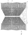
- FIG. 6 is an isometric view of the deep cleaning alignment equipment of FIG. 1 as the wedge is inserted into a heat recovery steam generator to spread a plurality of tubes to create a channel for a cleaning wand;
- FIG. 7 is a top plan view of the deep cleaning alignment equipment with the wedge spreading the plurality of tubes and the cleaning wand dispensing a cleaning solution to the heat recovery steam generator;
- FIG. 8 is a top plan view of the deep cleaning alignment equipment with the wedge spreading the plurality of tubes and the cleaning wand dispensing a cleaning solution to the heat recovery steam generator where the tubes are in a staggered configuration;
- FIG. 9 is a perspective view of one embodiment of a wand used with the deep cleaning alignment equipment.
- FIG. 12 is a perspective view of one potential nozzle used with the deep cleaning alignment equipment
- FIG. 19 is a perspective view of the wedge of FIGS. 17 - 18 inserted in a heat recovery steam generator system with the removable bracket inserted therein to remove the wedge from the system.
- the wedge 28 could be between three-and-a-half and five feet in length. In this embodiment the wedge 28 could be between approximately one-half inch and one inch in width. The specific size could vary based on the size of the module. For instance, where a boiler module contains twelve rows of tubes 24 , a three-and-a-half-foot wedge 28 would be used. For any modules having over twelve rows of tubes 24 , the longer five-foot wedge 28 could be used. Where the tubes 24 are located in close proximation to one another, the skinnier one-half inch wide wedge 28 would initially be used. After the one-half inch wedge 28 is inserted, a one-inch wide wedge can be inserted to further space the tubes 24 . Alternatively, tubes 24 with a greater initial distance from one another could simply be separated using the one-inch wide wedge 28 .
- the wedge 28 may be from approximately six inches to approximately nine feet in length, and more preferably between approximately three feet and approximately five feet in length. Additionally, the wedge 28 may have a height of approximately a half of an inch to a height of approximately two feet, and more preferably has a height between approximately two inches and approximately eight inches. Further still, the wedge 28 may have a width of between approximately 1 ⁇ 8 th of an inch and approximately four inches, and more preferably between approximately a half of an inch to approximately one and a half inches.
- the wedge 28 could be made of any other material that is softer than the tubes 24 and fins 26 associated with the tubes 24 , which are typically made of steel, for instance, various plastics, composites, and nylon materials.
- the wedge 28 could be configured such that it is both elongate and made of the composite component to minimize potential damage to the tubes 24 and fins 26 .
- the deep cleaning alignment equipment 20 may feature at least one cleaning wand 30 , as shown in detail in FIGS. 9 - 11 .
- the cleaning wand 30 is configured to spray a cleaning solution 34 of liquid or gas about the HRSG 22 . More specifically, the cleaning wand 30 may be configured to spray dry ice. This could include high density dry ice (CO2) pellets. These pellets will be propelled with ultra-high pressure air ranging from 200-350 psi. This would be advantageous as it would allow for cleaning of the HRSG 22 with the dry ice eventually evaporating. Of course, other types of media blasting could similarly occur.
- the cleaning wand 30 could similarly be configured to spray, other liquids or gas, including air, water, cleaning solution, and any other material capable of cleaning the tubes 24 and fins 26 .
- the cleaning wand 30 may have a first end 36 a second end 38 .
- the cleaning wand 30 may include a handle 40 to allow a user to firmly hold onto the cleaning wand 30 during use.
- an exit 42 is formed at the second end 38 .
- a supply channel 44 extends through the wand 30 to deliver the liquid or gas to the exit 42 .
- the exit 42 may direct liquid or gas straight out of the wand 30 .
- the exit 42 may direct liquid or gas out of the wand 30 at various angles. More specifically, FIGS.
- FIG. 7 , 9 , and 10 show a wand 30 capable of spraying liquid or gas out of the exit at an angle of approximately 45 degrees relative to the wand 30 , although the wand 30 could similarly be configured to exit at an angle of approximately 30 degrees or any other desired angle.
- the wand 30 could also be capable of front blowing and side blowing to clean the tubes 24 and fins 26 .
- the wands 30 could similarly blow liquid or gas at any other angle as desired.
- Additional wands 30 may also be used, such as a first wand to blow air to remove an initial layer of debris, and a second wand to shoot liquid or gas into the HRSG 22 .
- the wand 30 may have any number of different nozzle assemblies 46 to vary the way the liquid or gas is distributed from the wand 30 .
- FIG. 12 shows one potential nozzle 46 configuration.
- the HRSG absorbs heat energy from the exhaust gas stream of the combustion turbine.
- the absorbed heat energy is converted to thermal energy as high temperature and pressure steam.
- the high-pressure steam is then used in a steam turbine generator set to produce rotational mechanical energy.
- the shaft of the steam turbine is connected to an electrical generator that then produces electrical power.
- HRSGs can be classified as a double-wide, triple-pressure level with reheat, supplementary fired unit of natural circulation design, installed behind a natural gas fired combustion turbine.
- the steam generated by the HRSG is supplied to the steam turbine that drives the electrical generator system.
- HRSG Design The function of the combined cycle heat recovery steam generator (HRSG) system is to provide a method to extract sensible heat from the combustion turbine (CT) exhaust gas stream.
- CT combustion turbine
- the heat is converted into usable steam by the heat transfer surfaces within the HRSG.
- the usable steam is generated in three separate and different pressure levels for use in a steam turbine (ST) generator set and for power augmentation of the CT.
- ST steam turbine
- All generated steam from the HP, RH, and LP systems is supplied to the steam turbine, except for some LP steam used for deaeration.
- the IP steam is mixed with the cold RH return loop prior to being admitted to the steam turbine.
- Typical heat recovery steam generator circuits have four major components:
- a triple-pressure system may be operated of HP, IP, and LP, these components may be used for each associated pressure.
- These components (with the exception of the drum) are arranged in series in the gas flow path within the HRSG. Essentially, this means that the heat transfer boiler circuits are not in parallel with one another with respect to CT exhaust gas flow. The gas, after having been used to heat the water/steam in the HRSG is released to the environment through a stack.
- the HRSG does not have any moving parts, but it has thermal inertia, and rapid heating may result in high thermal stresses, which would affect the operating life of the HRSG.
- the high-pressure drum is most vulnerable to buildup of thermal stresses if heating is done very rapidly. To preclude this possibility, the drum is heated in a controlled manner.
- the magnitude of the stress depends on the temperature difference which, in turn, depends on the material type thickness, operating pressure of the component, and the fatigue life cycles.
- Controlling the pressure inside the drum can effectively control the temperature difference. If a certain temperature difference is close to the design limit, it can be controlled at that level by holding the pressure constant until the temperature difference decreases because of an increase in the component temperature due to conduction.
- the constant pressure or saturation temperature line on the drum heating chart indicates this.
- an HRSG Before an HRSG is put online, it is filled with water, and heat is applied. The cold metal takes some time to get heated, and time is required to soak the HRSG. The HRSG starts producing steam after a soaking period of a few minutes. If the steam is not released, then the pressure starts building up. The amount of steam produced and the increase in the pressure depend on the amount of heat supplied. More heat produces more steam, and pressure increases at a faster rate.
- the drum pressure can be controlled either by relieving the generated steam or by controlling the heat input to the boiler.
- a combination of both means is used to accomplish the controlled heating of the HRSG.
- the steam is relieved by venting to the atmosphere or by sending it to a heat sink such as a condenser.
- a heat sink such as a condenser.
- Operating the CT at reduced load controls the heat input.
- a gas-side bypass system which diverts part of the hot CT gasses to atmosphere, is sometimes used to control the heat input to the boiler. It is not necessary to run the CT at reduced load if a bypass system is provided.
- the IPSG is equipped with a system of three safety relief valves; typically, two are mounted vertically on top of the drum, and one is mounted vertically on the IP main steam header. All PSVs are closed during normal operation; however, in an overpressure situation, the IP superheater PSV will lift first. If the pressure continues to build, the IP drum PSVs will lift (lowest pressure setting first).
- the three PSVs are designed to relieve 100% of the total IP steam-generating capacity.
- Each module is multipass on the water side and single-pass on the gas side. This is accomplished by internal baffles in the upper and lower module headers.
- the IPEC receives feedwater from the feed pumps (provided by others) and absorbs heat from the CT exhaust gas, lowering the CT exhaust gas temperature and raising the water temperature to near saturation before entering the steam drum.
- the RH is equipped with an interstage attemperator located prior to the final reheater module.
- the attemperator is supplied for final steam temperature control.
- the spray attemperation process uses water as the cooling media.
- the spray water is directly fed to the attemperator from the IP feed pumps discharge line.
- Final steam temperature control is important for protection of the reheater and equipment served by the HRSG.
- the low-pressure steam generator includes an evaporator (LP EVAP) and a superheater (LPSH).
- LP EVAP evaporator
- LPSH superheater
- the two are circuit components and are in-series interspersed within the HRSG setting.
- the LPSG flow path is from the LP ECON, to the steam drum/evaporator, and finally to the superheater. There are no intervening valves between the steam drum and the superheater surface. The location of these heat transfer surfaces may be found on the Vogt-NEM sectional right-side elevation drawing.
- the LPSG is equipped with a system of three safety relief valves; typically, two are mounted vertically on top of the drum, and one is mounted vertically on the LP main steam header. All PSVs are closed during normal operation; however, in an overpressure situation, the LP superheater PSV will lift first. If the pressure continues to build, the LP drum PSVs will lift (lowest pressure setting first).
- the three PSVs are designed to relieve 100% of the total LP steam-generating capacity, including maximum pegging steam.
- Low-Pressure Evaporator The LP EVAP modules are all single-pass with no upper and lower header internal baffles. The modules are oriented in this direction to allow steam bubbles generated to escape via the riser tubes to the steam drum. Water is fed to the modules from the downcomer feeder header assemblies. This is referred to as a natural circulation loop.
Landscapes
- Engineering & Computer Science (AREA)
- Mechanical Engineering (AREA)
- General Engineering & Computer Science (AREA)
- Physics & Mathematics (AREA)
- Thermal Sciences (AREA)
- Chemical & Material Sciences (AREA)
- Combustion & Propulsion (AREA)
- Heat-Exchange Devices With Radiators And Conduit Assemblies (AREA)
Abstract
Description
-
- The first island within the combined-cycle power block is the combustion turbine (CT) generator set.
- The second island is the HRSG steam turbine generator set.
-
- High pressure (HP)
- Intermediate pressure (IP)
- Low pressure (LP)
- Reheat (RH)
- Feedwater preheater (FWPH)
-
- Superheaters
- Evaporators
- Economizers
- Drum
Claims (20)
Priority Applications (2)
| Application Number | Priority Date | Filing Date | Title |
|---|---|---|---|
| US17/729,133 US12270540B2 (en) | 2017-12-11 | 2022-04-26 | Deep cleaning alignment equipment |
| US18/783,800 US20240377147A1 (en) | 2017-12-11 | 2024-07-25 | Deep Cleaning Alignment Equipment |
Applications Claiming Priority (3)
| Application Number | Priority Date | Filing Date | Title |
|---|---|---|---|
| US201762597179P | 2017-12-11 | 2017-12-11 | |
| US16/204,281 US11313632B2 (en) | 2017-12-11 | 2018-11-29 | Deep cleaning alignment equipment |
| US17/729,133 US12270540B2 (en) | 2017-12-11 | 2022-04-26 | Deep cleaning alignment equipment |
Related Parent Applications (1)
| Application Number | Title | Priority Date | Filing Date |
|---|---|---|---|
| US16/204,281 Continuation-In-Part US11313632B2 (en) | 2017-12-11 | 2018-11-29 | Deep cleaning alignment equipment |
Related Child Applications (1)
| Application Number | Title | Priority Date | Filing Date |
|---|---|---|---|
| US18/783,800 Continuation-In-Part US20240377147A1 (en) | 2017-12-11 | 2024-07-25 | Deep Cleaning Alignment Equipment |
Publications (2)
| Publication Number | Publication Date |
|---|---|
| US20220252255A1 US20220252255A1 (en) | 2022-08-11 |
| US12270540B2 true US12270540B2 (en) | 2025-04-08 |
Family
ID=82703323
Family Applications (1)
| Application Number | Title | Priority Date | Filing Date |
|---|---|---|---|
| US17/729,133 Active 2039-12-21 US12270540B2 (en) | 2017-12-11 | 2022-04-26 | Deep cleaning alignment equipment |
Country Status (1)
| Country | Link |
|---|---|
| US (1) | US12270540B2 (en) |
Families Citing this family (1)
| Publication number | Priority date | Publication date | Assignee | Title |
|---|---|---|---|---|
| EP4685427A1 (en) * | 2024-07-25 | 2026-01-28 | Precision Iceblast Corporation | Deep cleaning alignment equipment |
Citations (22)
| Publication number | Priority date | Publication date | Assignee | Title |
|---|---|---|---|---|
| US2112896A (en) | 1935-05-23 | 1938-04-05 | Sellers William & Co Inc | Apparatus for cleaning heat exchangers and the like |
| US4344570A (en) * | 1980-08-11 | 1982-08-17 | Paseman Richard R | Apparatus for cleaning the interior of tubes |
| US4600115A (en) * | 1984-11-01 | 1986-07-15 | Framatome & Cie | Temporary obturation panel of a passage inside a vessel accessible only through an orifice of smaller size |
| US4827953A (en) | 1987-03-18 | 1989-05-09 | Electric Power Research Institute, Inc. | Flexible lance for steam generator secondary side sludge removable |
| US4831969A (en) | 1986-06-30 | 1989-05-23 | Man Gutehoffnungshuette Gmbh | Process and a device for cleaning inner or outer walls of vertically extending or inverted tubes of heat exchangers |
| US4980120A (en) * | 1989-12-12 | 1990-12-25 | The Babcock & Wilcox Company | Articulated sludge lance |
| US5194217A (en) | 1992-01-10 | 1993-03-16 | The Babcock & Wilcox Company | Articulated sludge lance with a movable extension nozzle |
| US5237718A (en) | 1992-05-01 | 1993-08-24 | The Babcock & Wilcox Company | Sootblower with lance bypass flow |
| US5555851A (en) | 1994-02-01 | 1996-09-17 | The Babcock & Wilcox Company | Automated sludge lance |
| US20040129388A1 (en) * | 2002-12-20 | 2004-07-08 | Brazil Bill Thomas | Non-marring tire lever |
| US7204208B2 (en) * | 2003-06-17 | 2007-04-17 | S.A. Robotics | Method and apparatuses to remove slag |
| US20080022949A1 (en) * | 2006-07-17 | 2008-01-31 | Harth George H | Heat exchanger framework |
| US20090230217A1 (en) * | 2008-03-14 | 2009-09-17 | Stone Ronald K | Insulated cleaning tool |
| US8002902B2 (en) * | 2008-05-15 | 2011-08-23 | Krowech Robert J | Boiler cleaning apparatus and method |
| US20120031350A1 (en) | 2010-08-06 | 2012-02-09 | General Electric Company | Ice blast cleaning systems and methods |
| US8238510B2 (en) | 2007-07-03 | 2012-08-07 | Westinghouse Electric Company Llc | Steam generator dual head sludge lance and process lancing system |
| US8752511B2 (en) | 2009-11-03 | 2014-06-17 | Westinghouse Electric Company Llc | Minature sludge lance apparatus |
| US20160116158A1 (en) * | 2014-10-24 | 2016-04-28 | Hrst, Inc. | Tube spreading device and boiler cleaning system |
| US20170016686A1 (en) | 2013-11-25 | 2017-01-19 | Geesco Co., Ltd. | Complex cleaning system for heat exchanger |
| US20170022460A1 (en) * | 2015-07-26 | 2017-01-26 | Talmor Suchard | On line chemical cleaning of air coolers |
| US20170089651A1 (en) * | 2015-09-30 | 2017-03-30 | Talmor Suchard | Chemical cleaning of furnaces, heaters and boilers during their operation |
| KR101748802B1 (en) | 2016-10-18 | 2017-06-19 | 주식회사 지스코 | Soot blower and method for cleaning tubular heat exchanger using thereof |
-
2022
- 2022-04-26 US US17/729,133 patent/US12270540B2/en active Active
Patent Citations (28)
| Publication number | Priority date | Publication date | Assignee | Title |
|---|---|---|---|---|
| US2112896A (en) | 1935-05-23 | 1938-04-05 | Sellers William & Co Inc | Apparatus for cleaning heat exchangers and the like |
| US4344570A (en) * | 1980-08-11 | 1982-08-17 | Paseman Richard R | Apparatus for cleaning the interior of tubes |
| US4600115A (en) * | 1984-11-01 | 1986-07-15 | Framatome & Cie | Temporary obturation panel of a passage inside a vessel accessible only through an orifice of smaller size |
| US4831969A (en) | 1986-06-30 | 1989-05-23 | Man Gutehoffnungshuette Gmbh | Process and a device for cleaning inner or outer walls of vertically extending or inverted tubes of heat exchangers |
| US4827953A (en) | 1987-03-18 | 1989-05-09 | Electric Power Research Institute, Inc. | Flexible lance for steam generator secondary side sludge removable |
| US4980120A (en) * | 1989-12-12 | 1990-12-25 | The Babcock & Wilcox Company | Articulated sludge lance |
| US5194217A (en) | 1992-01-10 | 1993-03-16 | The Babcock & Wilcox Company | Articulated sludge lance with a movable extension nozzle |
| US5237718A (en) | 1992-05-01 | 1993-08-24 | The Babcock & Wilcox Company | Sootblower with lance bypass flow |
| US5555851A (en) | 1994-02-01 | 1996-09-17 | The Babcock & Wilcox Company | Automated sludge lance |
| US5570660A (en) | 1994-02-01 | 1996-11-05 | The Babcock & Wilcox Company | Automated sludge lance |
| US5572957A (en) | 1994-02-01 | 1996-11-12 | The Babcock & Wilcox Company | Automated sludge lance |
| US20040129388A1 (en) * | 2002-12-20 | 2004-07-08 | Brazil Bill Thomas | Non-marring tire lever |
| US7204208B2 (en) * | 2003-06-17 | 2007-04-17 | S.A. Robotics | Method and apparatuses to remove slag |
| US20080022949A1 (en) * | 2006-07-17 | 2008-01-31 | Harth George H | Heat exchanger framework |
| US8238510B2 (en) | 2007-07-03 | 2012-08-07 | Westinghouse Electric Company Llc | Steam generator dual head sludge lance and process lancing system |
| US20090230217A1 (en) * | 2008-03-14 | 2009-09-17 | Stone Ronald K | Insulated cleaning tool |
| US8002902B2 (en) * | 2008-05-15 | 2011-08-23 | Krowech Robert J | Boiler cleaning apparatus and method |
| US8752511B2 (en) | 2009-11-03 | 2014-06-17 | Westinghouse Electric Company Llc | Minature sludge lance apparatus |
| US8757104B2 (en) | 2009-11-03 | 2014-06-24 | Westinghouse Electric Company Llc | Miniature sludge lance apparatus |
| US8800500B2 (en) | 2009-11-03 | 2014-08-12 | Westinghouse Electric Company Llc | Miniature sludge lance apparatus |
| US8800499B2 (en) | 2009-11-03 | 2014-08-12 | Westinghouse Electric Company Llc | Minature sludge lance apparatus |
| US20120031350A1 (en) | 2010-08-06 | 2012-02-09 | General Electric Company | Ice blast cleaning systems and methods |
| US20170016686A1 (en) | 2013-11-25 | 2017-01-19 | Geesco Co., Ltd. | Complex cleaning system for heat exchanger |
| US20160116158A1 (en) * | 2014-10-24 | 2016-04-28 | Hrst, Inc. | Tube spreading device and boiler cleaning system |
| US20170022460A1 (en) * | 2015-07-26 | 2017-01-26 | Talmor Suchard | On line chemical cleaning of air coolers |
| US20170089651A1 (en) * | 2015-09-30 | 2017-03-30 | Talmor Suchard | Chemical cleaning of furnaces, heaters and boilers during their operation |
| KR101748802B1 (en) | 2016-10-18 | 2017-06-19 | 주식회사 지스코 | Soot blower and method for cleaning tubular heat exchanger using thereof |
| US20190293372A1 (en) * | 2016-10-18 | 2019-09-26 | Geesco Co., Ltd. | Soot blower and method of cleaning tubular heat exchanger by using the same |
Non-Patent Citations (3)
| Title |
|---|
| International Search Report and Written Opinion of PCT/US2018/63295 dated Feb. 14, 2019 (13 pages). |
| Morgan Schwartz, Nylon Materials Offered by Stratasys and Comparing Nylon FDM Material—Which is better, TriMech Blog, Sep. 8, 2017, 9 pages. |
| Schwartz, "43. Comparing Nylon FDM materials: Which is better", https://blog.trimech.com/comparing-nylon-fdm-materials-which-is-better (Year: 2017). * |
Also Published As
| Publication number | Publication date |
|---|---|
| US20220252255A1 (en) | 2022-08-11 |
Similar Documents
| Publication | Publication Date | Title |
|---|---|---|
| US11313632B2 (en) | Deep cleaning alignment equipment | |
| US11761622B2 (en) | System and methods for integration of concentrated solar steam generators to Rankine cycle power plants | |
| US9696028B2 (en) | Module-based oxy-fuel boiler | |
| US6892523B2 (en) | Cooling-air cooler for a gas-turbine plant and use of such a cooling-air cooler | |
| US20190226364A1 (en) | Method and facility for recovering thermal energy on a furnace with tubular side members and for converting same into electricity by means of a turbine producing the electricity by implementing a rankine cycle | |
| US20140290244A1 (en) | Binary power generation system | |
| KR102438881B1 (en) | Once-through Vertical Tubular Supercritical Evaporator for Heat Recovery Steam Generator | |
| US12270540B2 (en) | Deep cleaning alignment equipment | |
| US6311647B1 (en) | Method and device for controlling the temperature at the outlet of a steam superheater | |
| CN101398167A (en) | Black plant steam furnace injection | |
| US20240377147A1 (en) | Deep Cleaning Alignment Equipment | |
| EP4685427A1 (en) | Deep cleaning alignment equipment | |
| ES2692406T3 (en) | Secondary water heater | |
| RU2351844C2 (en) | Uniflow steam generator of horizontal design type and method of uniflow steam generator operation | |
| ES2234765T3 (en) | METHOD FOR STEAM GENERATION USING A WASTE INCINERATOR. | |
| JP6221706B2 (en) | Boiler equipment | |
| CA1210653A (en) | Apparatus for superheating steam | |
| CA3055360A1 (en) | Systems and methods for integration of concentrated solar steam generators to rankine cycle power plants | |
| TH86474A (en) | Power plants with combined cycle and steam distribution methods For cooling of that part | |
| TH26471B (en) | Power plants with combined cycle and steam distribution methods For cooling of that part |
Legal Events
| Date | Code | Title | Description |
|---|---|---|---|
| FEPP | Fee payment procedure |
Free format text: ENTITY STATUS SET TO UNDISCOUNTED (ORIGINAL EVENT CODE: BIG.); ENTITY STATUS OF PATENT OWNER: SMALL ENTITY |
|
| FEPP | Fee payment procedure |
Free format text: ENTITY STATUS SET TO SMALL (ORIGINAL EVENT CODE: SMAL); ENTITY STATUS OF PATENT OWNER: SMALL ENTITY |
|
| STPP | Information on status: patent application and granting procedure in general |
Free format text: DOCKETED NEW CASE - READY FOR EXAMINATION |
|
| STPP | Information on status: patent application and granting procedure in general |
Free format text: NON FINAL ACTION MAILED |
|
| STPP | Information on status: patent application and granting procedure in general |
Free format text: RESPONSE TO NON-FINAL OFFICE ACTION ENTERED AND FORWARDED TO EXAMINER |
|
| STPP | Information on status: patent application and granting procedure in general |
Free format text: FINAL REJECTION MAILED |
|
| STPP | Information on status: patent application and granting procedure in general |
Free format text: RESPONSE AFTER FINAL ACTION FORWARDED TO EXAMINER |
|
| STPP | Information on status: patent application and granting procedure in general |
Free format text: NOTICE OF ALLOWANCE MAILED -- APPLICATION RECEIVED IN OFFICE OF PUBLICATIONS |
|
| AS | Assignment |
Owner name: PRECISION ICEBLAST CORPORATION, WISCONSIN Free format text: ASSIGNMENT OF ASSIGNORS INTEREST;ASSIGNORS:BOYE, KEITH R.;PETERSON, MATTHEW D.;SIGNING DATES FROM 20171220 TO 20171221;REEL/FRAME:070424/0655 Owner name: PRECISION ICEBLAST CORPORATION, WISCONSIN Free format text: ASSIGNMENT OF ASSIGNOR'S INTEREST;ASSIGNORS:BOYE, KEITH R.;PETERSON, MATTHEW D.;SIGNING DATES FROM 20171220 TO 20171221;REEL/FRAME:070424/0655 |
|
| STPP | Information on status: patent application and granting procedure in general |
Free format text: PUBLICATIONS -- ISSUE FEE PAYMENT VERIFIED |
|
| STCF | Information on status: patent grant |
Free format text: PATENTED CASE |