US12269446B2 - Hydraulic block for a hydraulic unit of a hydraulic vehicle braking system - Google Patents
Hydraulic block for a hydraulic unit of a hydraulic vehicle braking system Download PDFInfo
- Publication number
- US12269446B2 US12269446B2 US17/631,841 US202017631841A US12269446B2 US 12269446 B2 US12269446 B2 US 12269446B2 US 202017631841 A US202017631841 A US 202017631841A US 12269446 B2 US12269446 B2 US 12269446B2
- Authority
- US
- United States
- Prior art keywords
- plug connection
- hydraulic
- hydraulic block
- fluid reservoir
- brake fluid
- Prior art date
- Legal status (The legal status is an assumption and is not a legal conclusion. Google has not performed a legal analysis and makes no representation as to the accuracy of the status listed.)
- Active, expires
Links
Images


Classifications
-
- B—PERFORMING OPERATIONS; TRANSPORTING
- B60—VEHICLES IN GENERAL
- B60T—VEHICLE BRAKE CONTROL SYSTEMS OR PARTS THEREOF; BRAKE CONTROL SYSTEMS OR PARTS THEREOF, IN GENERAL; ARRANGEMENT OF BRAKING ELEMENTS ON VEHICLES IN GENERAL; PORTABLE DEVICES FOR PREVENTING UNWANTED MOVEMENT OF VEHICLES; VEHICLE MODIFICATIONS TO FACILITATE COOLING OF BRAKES
- B60T15/00—Construction arrangement, or operation of valves incorporated in power brake systems and not covered by groups B60T11/00 or B60T13/00
-
- B—PERFORMING OPERATIONS; TRANSPORTING
- B60—VEHICLES IN GENERAL
- B60T—VEHICLE BRAKE CONTROL SYSTEMS OR PARTS THEREOF; BRAKE CONTROL SYSTEMS OR PARTS THEREOF, IN GENERAL; ARRANGEMENT OF BRAKING ELEMENTS ON VEHICLES IN GENERAL; PORTABLE DEVICES FOR PREVENTING UNWANTED MOVEMENT OF VEHICLES; VEHICLE MODIFICATIONS TO FACILITATE COOLING OF BRAKES
- B60T13/00—Transmitting braking action from initiating means to ultimate brake actuator with power assistance or drive; Brake systems incorporating such transmitting means, e.g. air-pressure brake systems
- B60T13/10—Transmitting braking action from initiating means to ultimate brake actuator with power assistance or drive; Brake systems incorporating such transmitting means, e.g. air-pressure brake systems with fluid assistance, drive, or release
- B60T13/66—Electrical control in fluid-pressure brake systems
- B60T13/662—Electrical control in fluid-pressure brake systems characterised by specified functions of the control system components
-
- B—PERFORMING OPERATIONS; TRANSPORTING
- B60—VEHICLES IN GENERAL
- B60T—VEHICLE BRAKE CONTROL SYSTEMS OR PARTS THEREOF; BRAKE CONTROL SYSTEMS OR PARTS THEREOF, IN GENERAL; ARRANGEMENT OF BRAKING ELEMENTS ON VEHICLES IN GENERAL; PORTABLE DEVICES FOR PREVENTING UNWANTED MOVEMENT OF VEHICLES; VEHICLE MODIFICATIONS TO FACILITATE COOLING OF BRAKES
- B60T13/00—Transmitting braking action from initiating means to ultimate brake actuator with power assistance or drive; Brake systems incorporating such transmitting means, e.g. air-pressure brake systems
- B60T13/10—Transmitting braking action from initiating means to ultimate brake actuator with power assistance or drive; Brake systems incorporating such transmitting means, e.g. air-pressure brake systems with fluid assistance, drive, or release
- B60T13/66—Electrical control in fluid-pressure brake systems
- B60T13/68—Electrical control in fluid-pressure brake systems by electrically-controlled valves
- B60T13/686—Electrical control in fluid-pressure brake systems by electrically-controlled valves in hydraulic systems or parts thereof
-
- B—PERFORMING OPERATIONS; TRANSPORTING
- B60—VEHICLES IN GENERAL
- B60T—VEHICLE BRAKE CONTROL SYSTEMS OR PARTS THEREOF; BRAKE CONTROL SYSTEMS OR PARTS THEREOF, IN GENERAL; ARRANGEMENT OF BRAKING ELEMENTS ON VEHICLES IN GENERAL; PORTABLE DEVICES FOR PREVENTING UNWANTED MOVEMENT OF VEHICLES; VEHICLE MODIFICATIONS TO FACILITATE COOLING OF BRAKES
- B60T13/00—Transmitting braking action from initiating means to ultimate brake actuator with power assistance or drive; Brake systems incorporating such transmitting means, e.g. air-pressure brake systems
- B60T13/74—Transmitting braking action from initiating means to ultimate brake actuator with power assistance or drive; Brake systems incorporating such transmitting means, e.g. air-pressure brake systems with electrical assistance or drive
- B60T13/745—Transmitting braking action from initiating means to ultimate brake actuator with power assistance or drive; Brake systems incorporating such transmitting means, e.g. air-pressure brake systems with electrical assistance or drive acting on a hydraulic system, e.g. a master cylinder
-
- B—PERFORMING OPERATIONS; TRANSPORTING
- B60—VEHICLES IN GENERAL
- B60T—VEHICLE BRAKE CONTROL SYSTEMS OR PARTS THEREOF; BRAKE CONTROL SYSTEMS OR PARTS THEREOF, IN GENERAL; ARRANGEMENT OF BRAKING ELEMENTS ON VEHICLES IN GENERAL; PORTABLE DEVICES FOR PREVENTING UNWANTED MOVEMENT OF VEHICLES; VEHICLE MODIFICATIONS TO FACILITATE COOLING OF BRAKES
- B60T15/00—Construction arrangement, or operation of valves incorporated in power brake systems and not covered by groups B60T11/00 or B60T13/00
- B60T15/02—Application and release valves
- B60T15/025—Electrically controlled valves
- B60T15/028—Electrically controlled valves in hydraulic systems
-
- B—PERFORMING OPERATIONS; TRANSPORTING
- B60—VEHICLES IN GENERAL
- B60T—VEHICLE BRAKE CONTROL SYSTEMS OR PARTS THEREOF; BRAKE CONTROL SYSTEMS OR PARTS THEREOF, IN GENERAL; ARRANGEMENT OF BRAKING ELEMENTS ON VEHICLES IN GENERAL; PORTABLE DEVICES FOR PREVENTING UNWANTED MOVEMENT OF VEHICLES; VEHICLE MODIFICATIONS TO FACILITATE COOLING OF BRAKES
- B60T8/00—Arrangements for adjusting wheel-braking force to meet varying vehicular or ground-surface conditions, e.g. limiting or varying distribution of braking force
- B60T8/32—Arrangements for adjusting wheel-braking force to meet varying vehicular or ground-surface conditions, e.g. limiting or varying distribution of braking force responsive to a speed condition, e.g. acceleration or deceleration
- B60T8/34—Arrangements for adjusting wheel-braking force to meet varying vehicular or ground-surface conditions, e.g. limiting or varying distribution of braking force responsive to a speed condition, e.g. acceleration or deceleration having a fluid pressure regulator responsive to a speed condition
- B60T8/36—Arrangements for adjusting wheel-braking force to meet varying vehicular or ground-surface conditions, e.g. limiting or varying distribution of braking force responsive to a speed condition, e.g. acceleration or deceleration having a fluid pressure regulator responsive to a speed condition including a pilot valve responding to an electromagnetic force
- B60T8/3615—Electromagnetic valves specially adapted for anti-lock brake and traction control systems
- B60T8/3675—Electromagnetic valves specially adapted for anti-lock brake and traction control systems integrated in modulator units
- B60T8/368—Electromagnetic valves specially adapted for anti-lock brake and traction control systems integrated in modulator units combined with other mechanical components, e.g. pump units, master cylinders
-
- B—PERFORMING OPERATIONS; TRANSPORTING
- B60—VEHICLES IN GENERAL
- B60T—VEHICLE BRAKE CONTROL SYSTEMS OR PARTS THEREOF; BRAKE CONTROL SYSTEMS OR PARTS THEREOF, IN GENERAL; ARRANGEMENT OF BRAKING ELEMENTS ON VEHICLES IN GENERAL; PORTABLE DEVICES FOR PREVENTING UNWANTED MOVEMENT OF VEHICLES; VEHICLE MODIFICATIONS TO FACILITATE COOLING OF BRAKES
- B60T13/00—Transmitting braking action from initiating means to ultimate brake actuator with power assistance or drive; Brake systems incorporating such transmitting means, e.g. air-pressure brake systems
- B60T13/10—Transmitting braking action from initiating means to ultimate brake actuator with power assistance or drive; Brake systems incorporating such transmitting means, e.g. air-pressure brake systems with fluid assistance, drive, or release
- B60T13/12—Transmitting braking action from initiating means to ultimate brake actuator with power assistance or drive; Brake systems incorporating such transmitting means, e.g. air-pressure brake systems with fluid assistance, drive, or release the fluid being liquid
- B60T13/14—Transmitting braking action from initiating means to ultimate brake actuator with power assistance or drive; Brake systems incorporating such transmitting means, e.g. air-pressure brake systems with fluid assistance, drive, or release the fluid being liquid using accumulators or reservoirs fed by pumps
-
- B—PERFORMING OPERATIONS; TRANSPORTING
- B60—VEHICLES IN GENERAL
- B60Y—INDEXING SCHEME RELATING TO ASPECTS CROSS-CUTTING VEHICLE TECHNOLOGY
- B60Y2400/00—Special features of vehicle units
- B60Y2400/30—Sensors
- B60Y2400/306—Pressure sensors
-
- B—PERFORMING OPERATIONS; TRANSPORTING
- B60—VEHICLES IN GENERAL
- B60Y—INDEXING SCHEME RELATING TO ASPECTS CROSS-CUTTING VEHICLE TECHNOLOGY
- B60Y2400/00—Special features of vehicle units
- B60Y2400/81—Braking systems
Definitions
- a hydraulic block according to an example embodiment of the present invention is provided for a hydraulic unit of a hydraulic power vehicle braking system, which includes, in particular, a slip control.
- a main component of hydraulic power vehicle braking systems that include a slip control is a hydraulic unit including a hydraulic block to which hydraulic wheel brakes of the vehicle braking system are connected via brake lines.
- Slip controls are, in particular, anti-lock braking systems, traction control systems and/or dynamic stability controls/electronic stability programs, for which the abbreviations ABS, ASR and/or DSC/ESP are common. The latter are also referred to colloquial as “anti-skid controls.” Slip controls are conventional and are not further elaborated here.
- the hydraulic block includes no main brake cylinder bore, it is connectable, in particular, via brake lines, for example, to a main brake cylinder.
- the hydraulic block includes a main brake cylinder bore, it preferably also includes a receptacle for a pedal travel simulator.
- the pedal travel simulator includes a cylindrical blind hole in the hydraulic block, which is sealable with a cylindrical bowl-shaped cylinder cover in a pressure-resistant manner and which, together with the blind hole, forms a simulator cylinder, in which a, for example, spring-biased or gas pressure-biased simulator piston is displaceable.
- the hydraulic block according to an example embodiment of the present invention is used to mechanically fasten and to hydraulically interconnect hydraulic components of the vehicle braking system or of its slip control.
- hydraulic components are, among other things, solenoid valves, check valves, hydraulic accumulators, damper chambers, pressure sensors.
- the main brake cylinder, the pedal travel simulator and the power brake pressure generator are—if present—also components of the vehicle braking system or of its slip control.
- the hydraulic block forms a hydraulic unit, “fitted” meaning that the hydraulic components are fastened in the receptacles respectively provided for them.
- the present invention enables the check valve to be housed in the hydraulic block in a space-saving and streamlined manner.
- FIG. 1 shows a vertical cross section of a hydraulic block according to an example embodiment of the present invention.
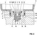
- FIG. 2 shows an enlarged representation of a plug connection of the hydraulic block for a brake fluid reservoir including an integrated check valve according to arrow II in FIG. 1 .
- Hydraulic block 1 serves as a mechanical fastening and hydraulic interconnection of hydraulic components of the slip control, including a brake pressure control of the power vehicle braking system.
- hydraulic components are, among other things, solenoid valves, check valves, hydraulic accumulators, damper chambers and pressure sensors, which are fastened in receptacles in the hydraulic block.
- the receptacles are cylindrical counter-bores, blind holes and/or also through-openings, which may include diameter gradations, and into which the hydraulic components are introduced and are fastened or become fastened in a pressure-tight manner, for example, as the result of a circumferential caulking.
- the hydraulic components may be countersunk in the receptacles or may project from hydraulic block 1 . Fitted with the hydraulic components, hydraulic block 1 forms the hydraulic unit for brake pressure generation using external power or muscular force and for brake pressure control and slip control of the power vehicle braking system.
- valve seat member 13 is fastened and sealed with so-called self-clinch technology in collar 8 in plug connection 3 .
- Valve seat member 13 holds the other parts of check valve 11 , namely shut-off body 12 and a valve spring 18 in collar 8 or in plug connection 3 .
- Other fastenings of valve seat member 13 are possible (not shown).
- shut-off valve 12 and/or of valve seat member 13 described above are not necessary for the present invention, check valve 11 and/or shut-off body 12 may be designed differently from that described above.
- Check valve 11 is located partly within collar 8 and connecting nipple 4 of brake fluid reservoir 5 inserted into plug connection 3 of hydraulic block 1 .
- filter screen 19 , valve seat member 13 and shut-off body 12 up to approximately its flange 15 are located within collar 8 and connecting nipple 4 inserted into plug connection 3 .
- Power cylinder bore 7 passes through hydraulic block 1 perpendicularly to opposing long sides 24 .
- Power cylinder bore 4 is used for displaceably accommodating a power piston not depicted of a power brake pressure generator, which is often referred to as a plunger piston.
- the power piston is displaceable in power cylinder bore 7 using an electric motor not depicted, which is mounted outside at one of the two long sides 24 of hydraulic block 1 coaxially to power cylinder bore 7 , via a planetary gear not shown as a mechanical reduction gear and a helical gear in the form of a ball screw drive also not shown.
Landscapes
- Engineering & Computer Science (AREA)
- Transportation (AREA)
- Mechanical Engineering (AREA)
- Physics & Mathematics (AREA)
- Electromagnetism (AREA)
- Fluid Mechanics (AREA)
- Regulating Braking Force (AREA)
- Valves And Accessory Devices For Braking Systems (AREA)
Abstract
Description
Claims (8)
Applications Claiming Priority (3)
| Application Number | Priority Date | Filing Date | Title |
|---|---|---|---|
| DE102019212356.2 | 2019-08-19 | ||
| DE102019212356.2A DE102019212356B4 (en) | 2019-08-19 | 2019-08-19 | Hydraulic block for a hydraulic unit of a hydraulic vehicle braking system |
| PCT/EP2020/064484 WO2021032330A1 (en) | 2019-08-19 | 2020-05-26 | Hydraulic block for a hydraulic unit of a hydraulic vehicle brake system |
Publications (2)
| Publication Number | Publication Date |
|---|---|
| US20220274578A1 US20220274578A1 (en) | 2022-09-01 |
| US12269446B2 true US12269446B2 (en) | 2025-04-08 |
Family
ID=70977931
Family Applications (1)
| Application Number | Title | Priority Date | Filing Date |
|---|---|---|---|
| US17/631,841 Active 2041-07-23 US12269446B2 (en) | 2019-08-19 | 2020-05-26 | Hydraulic block for a hydraulic unit of a hydraulic vehicle braking system |
Country Status (6)
| Country | Link |
|---|---|
| US (1) | US12269446B2 (en) |
| JP (1) | JP7598362B2 (en) |
| KR (1) | KR102852653B1 (en) |
| CN (1) | CN114206696B (en) |
| DE (1) | DE102019212356B4 (en) |
| WO (1) | WO2021032330A1 (en) |
Families Citing this family (4)
| Publication number | Priority date | Publication date | Assignee | Title |
|---|---|---|---|---|
| DE102020204459A1 (en) * | 2020-04-07 | 2021-10-07 | Robert Bosch Gesellschaft mit beschränkter Haftung | Hydraulic block for a hydraulic unit of an external hydraulic vehicle brake system |
| DE102021204255A1 (en) * | 2021-04-28 | 2022-11-03 | Robert Bosch Gesellschaft mit beschränkter Haftung | Hydraulic block for a service brake unit of a hydraulic power brake system |
| DE102021210766A1 (en) * | 2021-09-27 | 2023-03-30 | Robert Bosch Gesellschaft mit beschränkter Haftung | Hydraulic block for a hydraulic power brake system |
| KR20230135263A (en) * | 2022-03-16 | 2023-09-25 | 에이치엘만도 주식회사 | Check valve |
Citations (21)
| Publication number | Priority date | Publication date | Assignee | Title |
|---|---|---|---|---|
| US2152485A (en) | 1934-10-29 | 1939-03-28 | Gen Motors Corp | Master cylinder for hydraulic brakes |
| JPS57143560U (en) | 1981-03-02 | 1982-09-09 | ||
| JPS57170355U (en) | 1981-04-21 | 1982-10-27 | ||
| JPS5947565U (en) | 1982-09-23 | 1984-03-29 | アイシン精機株式会社 | master cylinder |
| US4445334A (en) | 1981-08-26 | 1984-05-01 | General Motors Corporation | Quick take-up master cylinder |
| US4736768A (en) * | 1985-09-26 | 1988-04-12 | Aisin Seiki Kabushiki Kaisha | Relief valve of hydraulic devices |
| US4773224A (en) * | 1985-10-18 | 1988-09-27 | Toyota Jidosha Kabushiki Kaisha | Portless type master cylinder device with non return valve and restricted passage in parallel between pressure chamber and fluid reservoir |
| JPS641051U (en) | 1987-06-16 | 1989-01-06 | ||
| US4951470A (en) | 1988-03-15 | 1990-08-28 | Alfred Teves Gmbh | Tandem master cylinder |
| US5590936A (en) | 1994-12-23 | 1997-01-07 | General Motors Corporation | Hydraulic ABS modulator |
| JPH09290718A (en) | 1996-04-26 | 1997-11-11 | Nabco Ltd | Automatic control brake system and tandem master cylinder used in this system |
| DE102010040380A1 (en) | 2010-09-08 | 2012-03-08 | Continental Teves Ag & Co. Ohg | Hydraulic unit for brake assembly of motor vehicle, has filter element which is arranged between low pressure storage section and pumping suction path which is connected to pressure retention valve and reversing valve |
| DE102012219054A1 (en) | 2012-10-18 | 2014-04-24 | Robert Bosch Gmbh | Hydraulic accumulator for hydraulic vehicle brake system, has housing provided with radial sealing surfaces to direct sealing against opposite surface and hydraulically connected with check valve |
| DE102014215076A1 (en) | 2014-07-31 | 2016-02-04 | Robert Bosch Gmbh | Driver brake force simulator for a brake system of a vehicle and method for producing a driver brake force simulator |
| CN106458178A (en) | 2014-06-13 | 2017-02-22 | 罗伯特·博世有限公司 | Hydraulic unit for slip control in a hydraulic vehicle braking system |
| US20170106846A1 (en) | 2015-10-19 | 2017-04-20 | Mando Corporation | Electric brake system |
| CN107000717A (en) | 2014-12-16 | 2017-08-01 | 罗伯特·博世有限公司 | Valve module, the hydraulic block for this vehicle brake apparatus and the vehicle brake apparatus with this hydraulic block for the pressure change damper of the hydraulic vehicle brake equipment with brake-force control function |
| DE102016202113A1 (en) | 2016-02-12 | 2017-08-17 | Robert Bosch Gmbh | Hydraulic block for a brake system of a motor vehicle and brake system for a motor vehicle |
| DE102016206785A1 (en) | 2016-04-21 | 2017-10-26 | Robert Bosch Gmbh | Hydraulic block and method of manufacturing a hydraulic block with at least one check valve |
| DE102017216001A1 (en) | 2017-09-12 | 2019-03-14 | Robert Bosch Gmbh | Hydraulic block for a hydraulic power-operated vehicle brake system |
| WO2019145820A1 (en) | 2018-01-23 | 2019-08-01 | ローベルト ボッシュ ゲゼルシャフト ミット ベシュレンクテル ハフツング | Brake hydraulic pressure controller |
-
2019
- 2019-08-19 DE DE102019212356.2A patent/DE102019212356B4/en active Active
-
2020
- 2020-05-26 KR KR1020227008699A patent/KR102852653B1/en active Active
- 2020-05-26 JP JP2022508598A patent/JP7598362B2/en active Active
- 2020-05-26 CN CN202080058559.3A patent/CN114206696B/en active Active
- 2020-05-26 WO PCT/EP2020/064484 patent/WO2021032330A1/en not_active Ceased
- 2020-05-26 US US17/631,841 patent/US12269446B2/en active Active
Patent Citations (23)
| Publication number | Priority date | Publication date | Assignee | Title |
|---|---|---|---|---|
| US2152485A (en) | 1934-10-29 | 1939-03-28 | Gen Motors Corp | Master cylinder for hydraulic brakes |
| JPS57143560U (en) | 1981-03-02 | 1982-09-09 | ||
| JPS57170355U (en) | 1981-04-21 | 1982-10-27 | ||
| US4445334A (en) | 1981-08-26 | 1984-05-01 | General Motors Corporation | Quick take-up master cylinder |
| JPS5947565U (en) | 1982-09-23 | 1984-03-29 | アイシン精機株式会社 | master cylinder |
| US4736768A (en) * | 1985-09-26 | 1988-04-12 | Aisin Seiki Kabushiki Kaisha | Relief valve of hydraulic devices |
| US4773224A (en) * | 1985-10-18 | 1988-09-27 | Toyota Jidosha Kabushiki Kaisha | Portless type master cylinder device with non return valve and restricted passage in parallel between pressure chamber and fluid reservoir |
| JPS641051U (en) | 1987-06-16 | 1989-01-06 | ||
| US4951470A (en) | 1988-03-15 | 1990-08-28 | Alfred Teves Gmbh | Tandem master cylinder |
| US5590936A (en) | 1994-12-23 | 1997-01-07 | General Motors Corporation | Hydraulic ABS modulator |
| JPH09290718A (en) | 1996-04-26 | 1997-11-11 | Nabco Ltd | Automatic control brake system and tandem master cylinder used in this system |
| DE102010040380A1 (en) | 2010-09-08 | 2012-03-08 | Continental Teves Ag & Co. Ohg | Hydraulic unit for brake assembly of motor vehicle, has filter element which is arranged between low pressure storage section and pumping suction path which is connected to pressure retention valve and reversing valve |
| DE102012219054A1 (en) | 2012-10-18 | 2014-04-24 | Robert Bosch Gmbh | Hydraulic accumulator for hydraulic vehicle brake system, has housing provided with radial sealing surfaces to direct sealing against opposite surface and hydraulically connected with check valve |
| CN106458178A (en) | 2014-06-13 | 2017-02-22 | 罗伯特·博世有限公司 | Hydraulic unit for slip control in a hydraulic vehicle braking system |
| DE102014215076A1 (en) | 2014-07-31 | 2016-02-04 | Robert Bosch Gmbh | Driver brake force simulator for a brake system of a vehicle and method for producing a driver brake force simulator |
| US10053073B2 (en) * | 2014-07-31 | 2018-08-21 | Robert Bosch Gmbh | Driver brake force simulator for a braking system of a vehicle, and manufacturing method for a driver brake force simulator |
| CN107000717A (en) | 2014-12-16 | 2017-08-01 | 罗伯特·博世有限公司 | Valve module, the hydraulic block for this vehicle brake apparatus and the vehicle brake apparatus with this hydraulic block for the pressure change damper of the hydraulic vehicle brake equipment with brake-force control function |
| US20170106846A1 (en) | 2015-10-19 | 2017-04-20 | Mando Corporation | Electric brake system |
| DE102016202113A1 (en) | 2016-02-12 | 2017-08-17 | Robert Bosch Gmbh | Hydraulic block for a brake system of a motor vehicle and brake system for a motor vehicle |
| DE102016206785A1 (en) | 2016-04-21 | 2017-10-26 | Robert Bosch Gmbh | Hydraulic block and method of manufacturing a hydraulic block with at least one check valve |
| US10730493B2 (en) * | 2016-04-21 | 2020-08-04 | Robert Bosch Gmbh | Hydraulic block and manufacturing method for a hydraulic block including at least one check valve |
| DE102017216001A1 (en) | 2017-09-12 | 2019-03-14 | Robert Bosch Gmbh | Hydraulic block for a hydraulic power-operated vehicle brake system |
| WO2019145820A1 (en) | 2018-01-23 | 2019-08-01 | ローベルト ボッシュ ゲゼルシャフト ミット ベシュレンクテル ハフツング | Brake hydraulic pressure controller |
Non-Patent Citations (2)
| Title |
|---|
| International Search Report for PCT/EP2020/064484, Issued Jul. 21, 2020. |
| Translation of Japanese Patent No. JPS 57-170355 obtained from website: https://worldwide.espacenet.com on Mar. 18, 2024. * |
Also Published As
| Publication number | Publication date |
|---|---|
| DE102019212356A1 (en) | 2021-02-25 |
| US20220274578A1 (en) | 2022-09-01 |
| CN114206696B (en) | 2024-03-22 |
| DE102019212356B4 (en) | 2024-10-02 |
| KR20220047354A (en) | 2022-04-15 |
| JP2022544261A (en) | 2022-10-17 |
| WO2021032330A1 (en) | 2021-02-25 |
| KR102852653B1 (en) | 2025-08-29 |
| CN114206696A (en) | 2022-03-18 |
| JP7598362B2 (en) | 2024-12-11 |
Similar Documents
| Publication | Publication Date | Title |
|---|---|---|
| US12269446B2 (en) | Hydraulic block for a hydraulic unit of a hydraulic vehicle braking system | |
| US11220250B2 (en) | Hydraulic block for a hydraulic power brake system of a vehicle | |
| JP7792962B2 (en) | Rectangular hydraulic block for hydraulic units of brake pressure control for hydraulic vehicle brake equipment | |
| US11608044B2 (en) | Hydraulic block for a hydraulic power vehicle braking system | |
| US11760324B2 (en) | Hydraulic block for a hydraulic unit for a hydraulic vehicle braking system | |
| US9637100B2 (en) | Hydraulic unit for a slip control system of a hydraulic vehicle brake system | |
| CN114728640B (en) | Hydraulic blocks for hydraulic assemblies of hydraulic vehicle brake systems | |
| US20210354670A1 (en) | Hydraulic block for a hydraulic modulator of a vehicle hydraulic-power brake system | |
| US11904823B2 (en) | Hydraulic block for a hydraulic power unit of a hydraulic power vehicle braking system | |
| JP2023119579A (en) | Hydraulic blocks for hydraulic non-manpower braking systems | |
| US12403872B2 (en) | Hydraulic block for a brake unit of a hydraulic power brake system | |
| US12162445B2 (en) | Hydraulic unit for a service brake assembly of a hydraulic power-brake system | |
| JP7397168B2 (en) | Hydraulic blocks for hydraulic units of hydraulic auxiliary power vehicle braking systems | |
| JP6833046B2 (en) | Hydraulic block for hydraulic device of brake control system of hydraulic vehicle brake device | |
| JP7851335B2 (en) | Hydraulic block for brake unit of hydraulic non-manual brake equipment | |
| CN115871628A (en) | Hydraulic block of hydraulic assembly of hydraulic external force braking equipment | |
| JP2004142603A (en) | Vehicle brake system | |
| JPS61113544A (en) | Vehicle brake hydraulic control device |
Legal Events
| Date | Code | Title | Description |
|---|---|---|---|
| FEPP | Fee payment procedure |
Free format text: ENTITY STATUS SET TO UNDISCOUNTED (ORIGINAL EVENT CODE: BIG.); ENTITY STATUS OF PATENT OWNER: LARGE ENTITY |
|
| STPP | Information on status: patent application and granting procedure in general |
Free format text: DOCKETED NEW CASE - READY FOR EXAMINATION |
|
| AS | Assignment |
Owner name: ROBERT BOSCH GMBH, GERMANY Free format text: ASSIGNMENT OF ASSIGNORS INTEREST;ASSIGNOR:WEH, ANDREAS;REEL/FRAME:060428/0330 Effective date: 20220222 |
|
| STPP | Information on status: patent application and granting procedure in general |
Free format text: NON FINAL ACTION MAILED |
|
| STPP | Information on status: patent application and granting procedure in general |
Free format text: RESPONSE TO NON-FINAL OFFICE ACTION ENTERED AND FORWARDED TO EXAMINER |
|
| STPP | Information on status: patent application and granting procedure in general |
Free format text: FINAL REJECTION MAILED |
|
| STPP | Information on status: patent application and granting procedure in general |
Free format text: RESPONSE AFTER FINAL ACTION FORWARDED TO EXAMINER |
|
| STPP | Information on status: patent application and granting procedure in general |
Free format text: NOTICE OF ALLOWANCE MAILED -- APPLICATION RECEIVED IN OFFICE OF PUBLICATIONS |
|
| STPP | Information on status: patent application and granting procedure in general |
Free format text: PUBLICATIONS -- ISSUE FEE PAYMENT RECEIVED |
|
| STCF | Information on status: patent grant |
Free format text: PATENTED CASE |