US12268640B2 - Casket ornament attachment mechanism - Google Patents

Casket ornament attachment mechanism Download PDF

Info

Publication number
US12268640B2
US12268640B2 US18/602,405 US202418602405A US12268640B2 US 12268640 B2 US12268640 B2 US 12268640B2 US 202418602405 A US202418602405 A US 202418602405A US 12268640 B2 US12268640 B2 US 12268640B2
Authority
US
United States
Prior art keywords
ornament
decorative ornament
adapter
foot
plaque
Prior art date
Legal status (The legal status is an assumption and is not a legal conclusion. Google has not performed a legal analysis and makes no representation as to the accuracy of the status listed.)
Active
Application number
US18/602,405
Other versions
US20240216206A1 (en
Inventor
Kristine Ann Reynolds
Todd Jefferey Tekulve
Gregory Wray
Current Assignee (The listed assignees may be inaccurate. Google has not performed a legal analysis and makes no representation or warranty as to the accuracy of the list.)
Batesville Services Inc
Original Assignee
Batesville Services Inc
Priority date (The priority date is an assumption and is not a legal conclusion. Google has not performed a legal analysis and makes no representation as to the accuracy of the date listed.)
Filing date
Publication date
Application filed by Batesville Services Inc filed Critical Batesville Services Inc
Priority to US18/602,405 priority Critical patent/US12268640B2/en
Assigned to BATESVILLE SERVICES, INC. reassignment BATESVILLE SERVICES, INC. ASSIGNMENT OF ASSIGNORS INTEREST (SEE DOCUMENT FOR DETAILS). Assignors: TEKULVE, TODD JEFFEREY, REYNOLDS, KRISTINE ANN, WRAY, GREGORY
Publication of US20240216206A1 publication Critical patent/US20240216206A1/en
Application granted granted Critical
Publication of US12268640B2 publication Critical patent/US12268640B2/en
Active legal-status Critical Current
Anticipated expiration legal-status Critical

Links

Images

Classifications

    • AHUMAN NECESSITIES
    • A61MEDICAL OR VETERINARY SCIENCE; HYGIENE
    • A61GTRANSPORT, PERSONAL CONVEYANCES, OR ACCOMMODATION SPECIALLY ADAPTED FOR PATIENTS OR DISABLED PERSONS; OPERATING TABLES OR CHAIRS; CHAIRS FOR DENTISTRY; FUNERAL DEVICES
    • A61G17/00Coffins; Funeral wrappings; Funeral urns
    • A61G17/04Fittings for coffins
    • A61G17/0407Corner structures
    • AHUMAN NECESSITIES
    • A61MEDICAL OR VETERINARY SCIENCE; HYGIENE
    • A61GTRANSPORT, PERSONAL CONVEYANCES, OR ACCOMMODATION SPECIALLY ADAPTED FOR PATIENTS OR DISABLED PERSONS; OPERATING TABLES OR CHAIRS; CHAIRS FOR DENTISTRY; FUNERAL DEVICES
    • A61G17/00Coffins; Funeral wrappings; Funeral urns
    • A61G17/08Urns
    • AHUMAN NECESSITIES
    • A61MEDICAL OR VETERINARY SCIENCE; HYGIENE
    • A61GTRANSPORT, PERSONAL CONVEYANCES, OR ACCOMMODATION SPECIALLY ADAPTED FOR PATIENTS OR DISABLED PERSONS; OPERATING TABLES OR CHAIRS; CHAIRS FOR DENTISTRY; FUNERAL DEVICES
    • A61G17/00Coffins; Funeral wrappings; Funeral urns
    • A61G17/04Fittings for coffins
    • A61G17/045Rack for flowers

Definitions

  • This invention relates generally to caskets, and more particularly to mechanisms for attaching ornaments to caskets.
  • the casket corner ornaments of the '466, 706, and '810 patents, and the '579 publication utilize fasteners with heads, for example shoulder screws, mounted on the flat or planar rear side of the ornament, the heads of which are secured in keyhole slots or grooves, for example L-shaped keyhole slots or grooves, in the casket shell corners.
  • These ornaments are commercially available from the assignee as its LIFESYMBOLS® line of casket shell corner ornaments.
  • Each keyhole-shaped groove can be L-shaped.
  • the foot of the adapter can include an upstanding post thereon and the ornament can have a hole extending upwardly from a bottom thereof into the ornament; the post can thus be received in the hole as the ornament is positioned on the foot of the adapter to secure the ornament to the adapter.
  • the keyhole-shaped grooves can be formed in a clip that is attached to the casket shell corner.
  • FIG. 1 is a perspective view of one corner of a casket with a casket corner ornament of the present invention that is three-dimensional the entire 360 degrees about a vertical axis of the ornament and that is mounted to the casket corner adapter of the present invention;
  • FIG. 2 A is a view similar to FIG. 1 illustrating the step of mounting the adapter to the casket corner;
  • FIG. 2 B is a view similar to FIG. 2 A illustrating the step of mounting the ornament to the adapter
  • FIG. 3 A is a side view of the casket corner, in partial cross-section, illustrating the step of mounting the adapter to the casket corner;
  • FIG. 3 B is a view similar to FIG. 3 A illustrating the step of mounting the ornament to the adapter:
  • FIG. 3 C is a view similar to FIG. 3 B illustrating the adapter mounted to the casket corner and the ornament mounted to the adapter;
  • FIG. 4 is a perspective view illustrating the adapter mounted to a cremation urn and the ornament mounted to the adapter;
  • FIGS. 5 A and 5 B are front perspective views illustrating the ornament mounted to a base:
  • FIG. 6 is a front perspective view of another cremation urn illustrating the ornament and base of FIGS. 5 A and 5 B mounted thereon;
  • FIG. 7 is a front view of a plaque with the adapter mounted thereto and the ornament mounted to the adapter.
  • FIGS. 1 , 2 A, and 2 B there is illustrated a casket 10 having a casket shell 12 with a pair of side walls 14 and a pair of end walls 16 .
  • the casket 10 has at least one lid 18 thereon.
  • the casket shell 12 has a 45-degree corner 20 at adjacent ends of the side walls 14 and end walls 16 .
  • a clip 30 is recessed into the corner 20 .
  • the clip 30 has a pair of right-angle or L-shaped keyhole-shaped grooves 32 , 34 formed therein.
  • Each keyhole groove 32 , 34 has a generally circular opening 40 , a first generally horizontal linear groove 42 communicating with the opening 42 and a second generally vertical groove 44 communicating with the first groove 42 .
  • the clip 30 can be molded of plastic.
  • the clip 30 can be used with metal caskets and with wood caskets.
  • the casket need not even use such a clip 30 , as long as the 45-degree corner portions of the casket shell (metal or wood) have the pair of right-angle keyhole-shaped grooves formed therein.
  • An adaptor 50 is generally L-shaped and has a generally vertical leg 52 and a generally horizontal foot 54 connected to a lower end of the leg 52 .
  • the foot 54 has an upstanding post 56 extending upwardly from the foot 54 .
  • the leg 52 has a pair of studs 60 on a rear side thereof.
  • Each stud 60 has a head 62 thereon.
  • Each head 62 is received in a respective one of said keyhole-shaped grooves 32 , 34 . More particularly, each head 62 is inserted into a respective opening 42 . Thereafter, the adapter 50 is moved horizontally to the right such that each head 62 is retained behind its respective horizontal groove 42 .

Landscapes

  • Health & Medical Sciences (AREA)
  • Life Sciences & Earth Sciences (AREA)
  • Animal Behavior & Ethology (AREA)
  • General Health & Medical Sciences (AREA)
  • Public Health (AREA)
  • Veterinary Medicine (AREA)
  • Adornments (AREA)
  • Toys (AREA)

Abstract

A combination cremation urn and ornament comprises a base adapted to receive cremation ashes therein, an upstanding post mounted to an upper surface of said base and extending upwardly therefrom, and a decorative ornament that is three-dimensional an entire 360 degrees about a vertical axis of said decorative ornament, said decorative ornament having a hole extending upwardly from a bottom thereof into said decorative ornament, said post received in said hole as said decorative ornament is positioned on said base to secure said decorative ornament to said base.

Description

CROSS-REFERENCE TO RELATED APPLICATIONS
This application is a continuation of U.S. patent application Ser. No. 18/157,876, filed Jan. 23, 2023, which is a divisional of U.S. patent application Ser. No. 17/349,511 filed Jun. 16, 2021, which is a divisional of U.S. patent application Ser. No. 16/598,186 filed Oct. 10, 2019, which claims the priority benefit of U.S. Provisional Patent Application No. 62/745,053 filed Oct. 12, 2018, which are hereby incorporated by reference herein as if fully set forth in their entirety.
FIELD OF THE INVENTION
This invention relates generally to caskets, and more particularly to mechanisms for attaching ornaments to caskets.
BACKGROUND OF THE INVENTION
It is known to attach decorative ornaments to caskets to “personalize” the casket to the deceased. Over the years various mechanisms have been devised by the assignee to attach decorative ornaments to funerary articles, and more particularly, to attach decorative corner ornaments to casket corners.
Examples of mechanisms for attaching decorative “figurine” style ornaments to the exterior of a casket, for example to the corners of the casket shell, are shown in, for example, the assignee's U.S. Pat. Nos. 6,591,466, 6,928,706, 7,340,810 and 7,591,052, and US Patent Application Publication No. 2010/0077579, all hereby incorporated by reference herein as if fully set forth in their entireties. The casket corner ornaments of the '466, 706, and '810 patents, and the '579 publication, utilize fasteners with heads, for example shoulder screws, mounted on the flat or planar rear side of the ornament, the heads of which are secured in keyhole slots or grooves, for example L-shaped keyhole slots or grooves, in the casket shell corners. These ornaments are commercially available from the assignee as its LIFESYMBOLS® line of casket shell corner ornaments.
Nevertheless, there remains room for improvement in such casket ornaments and casket ornament attachment mechanisms.
SUMMARY OF THE INVENTION
In one aspect, a combination casket and ornament comprises a casket shell having a pair of keyhole-shaped grooves in a corner thereof, an L-shaped adapter having a leg and a foot, the leg having a pair of studs on a rear side thereof each of which is received in a respective one of the keyhole-shaped grooves, and a decorative ornament that is three-dimensional an entire 360 degrees about a vertical axis of the ornament, the ornament positioned on the foot of the L-shaped adapter.
Each keyhole-shaped groove can be L-shaped. The foot of the adapter can include an upstanding post thereon and the ornament can have a hole extending upwardly from a bottom thereof into the ornament; the post can thus be received in the hole as the ornament is positioned on the foot of the adapter to secure the ornament to the adapter. The keyhole-shaped grooves can be formed in a clip that is attached to the casket shell corner.
In another aspect, a combination cremation urn and ornament comprises a cremation ashes receptacle having a pair of keyhole-shaped grooves in a surface thereof, an L-shaped adapter having a leg and a foot, the leg having a pair of studs on a rear side thereof each of which is received in a respective one of the keyhole-shaped grooves, and a decorative ornament that is three-dimensional an entire 360 degrees about a vertical axis of the ornament, the ornament positioned on the foot of the L-shaped adapter.
In yet another aspect, a combination cremation urn and ornament comprises a base adapted to receive a small amount of cremation ashes therein, an upstanding post mounted to an upper surface of the base and extending upwardly therefrom, and a decorative ornament that is three-dimensional an entire 360 degrees about a vertical axis of the ornament, the ornament having a hole extending upwardly from a bottom thereof into the ornament, the post received in the hole as the ornament is positioned on the base to secure the ornament to the base.
In yet another aspect, a memorial plaque comprises a plaque surface having a pair of keyhole-shaped grooves therein, an L-shaped adapter having a leg and a foot, the leg having a pair of studs on a rear side thereof each of which is received in a respective one of the keyhole-shaped grooves, the foot having an upstanding post thereon, and a decorative ornament that is three-dimensional an entire 360 degrees about a vertical axis of the ornament, the ornament having a hole extending upwardly from a bottom thereof into the ornament, the post received in the hole as the ornament is positioned on the foot of the adapter to secure the ornament to the adapter.
In yet another aspect, a combination funerary ornament and mount comprises an L-shaped adapter having a leg and a foot, the leg having a pair of studs on a rear side thereof each of which is adapted to be received in a respective keyhole-shaped groove of a casket shell, a cremation urn, or a memorial plaque, the foot having an upstanding post thereon, and a decorative ornament that is three-dimensional an entire 360 degrees about a vertical axis of the ornament, the ornament positioned on the foot of the L-shaped adapter, the ornament having a hole extending upwardly from a bottom thereof into the ornament, the post received in the hole as the ornament is positioned on the foot of the adapter to secure the ornament to the adapter.
The accompanying drawings, which are incorporated in and constitute a part of this specification, illustrate embodiments of the invention and, together with the summary of the invention given above, and the detailed description of the drawings given below, serve to explain the principles of the present invention.
BRIEF SUMMARY OF THE DRAWINGS
FIG. 1 is a perspective view of one corner of a casket with a casket corner ornament of the present invention that is three-dimensional the entire 360 degrees about a vertical axis of the ornament and that is mounted to the casket corner adapter of the present invention;
FIG. 2A is a view similar to FIG. 1 illustrating the step of mounting the adapter to the casket corner;
FIG. 2B is a view similar to FIG. 2A illustrating the step of mounting the ornament to the adapter;
FIG. 3A is a side view of the casket corner, in partial cross-section, illustrating the step of mounting the adapter to the casket corner;
FIG. 3B is a view similar to FIG. 3A illustrating the step of mounting the ornament to the adapter:
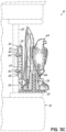
FIG. 3C is a view similar to FIG. 3B illustrating the adapter mounted to the casket corner and the ornament mounted to the adapter;
FIG. 4 is a perspective view illustrating the adapter mounted to a cremation urn and the ornament mounted to the adapter;
FIGS. 5A and 5B are front perspective views illustrating the ornament mounted to a base:
FIG. 6 is a front perspective view of another cremation urn illustrating the ornament and base of FIGS. 5A and 5B mounted thereon; and
FIG. 7 is a front view of a plaque with the adapter mounted thereto and the ornament mounted to the adapter.
DETAILED DESCRIPTION OF THE DRAWINGS
Referring first to FIGS. 1, 2A, and 2B, there is illustrated a casket 10 having a casket shell 12 with a pair of side walls 14 and a pair of end walls 16. The casket 10 has at least one lid 18 thereon. The casket shell 12 has a 45-degree corner 20 at adjacent ends of the side walls 14 and end walls 16. A clip 30 is recessed into the corner 20. The clip 30 has a pair of right-angle or L-shaped keyhole- shaped grooves 32, 34 formed therein. Each keyhole groove 32, 34 has a generally circular opening 40, a first generally horizontal linear groove 42 communicating with the opening 42 and a second generally vertical groove 44 communicating with the first groove 42. The clip 30 can be molded of plastic. Note that the clip 30 can be used with metal caskets and with wood caskets. For that matter, the casket need not even use such a clip 30, as long as the 45-degree corner portions of the casket shell (metal or wood) have the pair of right-angle keyhole-shaped grooves formed therein.
An adaptor 50 is generally L-shaped and has a generally vertical leg 52 and a generally horizontal foot 54 connected to a lower end of the leg 52. The foot 54 has an upstanding post 56 extending upwardly from the foot 54. The leg 52 has a pair of studs 60 on a rear side thereof. Each stud 60 has a head 62 thereon. Each head 62 is received in a respective one of said keyhole- shaped grooves 32, 34. More particularly, each head 62 is inserted into a respective opening 42. Thereafter, the adapter 50 is moved horizontally to the right such that each head 62 is retained behind its respective horizontal groove 42. When the adapter 50 cannot be moved any further to the right, the adapter 50 is then moved vertically downwardly until the studs 60 bottom out in their respective vertical grooves 44. The adapter 50 can be molded of plastic, and preferably clear plastic, so as to be as inconspicuous as possible.
A decorative ornament 64 is three-dimensional an entire 360 degrees about a vertical axis of the ornament. In other words, the ornament 64 does not have a planar back like the prior art type of decorative ornaments. The ornament has a cylindrical hole 66 (FIG. 3B) that extends upwardly from the bottom of the ornament 64 up into the body of the ornament 64. The ornament 64 can thus be placed on the foot 54 of the adapter 50, the post 56 residing in the cylindrical hole 66. Alternatively, or additionally, a plastic sleeve (not shown) can be pressed into the cylindrical hole 66 to provide a more snug connection between the post 56 and ornament 64.
FIGS. 3A-3C illustrate the steps in attaching the adapter 50 to the clip 30, and the ornament 64 to the adapter 50. Due to the height of the ornament 64, it will likely need to be installed on the adapter 50 first, and the adapter 50, with ornament 64 installed thereon, can be installed on the clip 30. For shorter ornaments, the adapter 50 can be installed to the clip 30 first, and then the ornament 64 can be installed to the adapter 50.
FIG. 4 illustrates an alternative embodiment wherein a cremation urn 70 has a clip 30 attached thereto. The adapter 50 can then be installed on the urn 70, and the ornament 64 can then be installed on the adapter 50. As in the prior embodiment, the urn need not even use such a clip 30, as long as a surface of the urn (metal or wood) has the pair of right-angle keyhole-shaped grooves formed therein.
FIGS. 5A and 5B illustrate another alternative embodiment. In this embodiment, a base 80 or “puck” has the upstanding post 56 mounted to an upper surface thereof. The base or puck 80 can have an openable and closeable cover on a lower surface thereof (not shown) so that a small amount of cremation ashes can be stored therein. The ornament 64 is mounted on the base 80, with the post 56 received in the cylindrical hole 66 of the ornament 60.
FIG. 6 illustrates yet another alternative embodiment. In this embodiment, a cremation urn 90 has the base 80 with ornament 64 mounted thereon placed atop the urn 90. Again, the ornament 64 is mounted on the base 80, with the post 56 received in the cylindrical hole 66 of the ornament 64.
FIG. 7 illustrates still another alternative embodiment. In this embodiment, a memorial plaque 100 has a clip 30 mounted thereto, and the adapter 50 is secured to the clip 30. Then, the ornament 64 is mounted on the adapter 50, with the post 56 of the adapter 50 being received in the cylindrical hole 66 of the ornament 64. As with the prior casket and urn embodiments, the plaque need not even use such a clip 30, as long as a surface of the plaque (metal or wood) has the pair of right-angle keyhole-shaped grooves formed therein.
Note that the adapter 50 could have a pair of magnets mounted to a rear side thereof as by screws or the like. In this way, the adapter 50 with ornament 64 thereon can be magnetically attached to a ferrous/magnetic cap panel of the casket.
The various embodiments of the invention shown and described are merely for illustrative purposes only, as the drawings and the description are not intended to restrict or limit in any way the scope of the claims. Those skilled in the art will appreciate various changes, modifications, and improvements which can be made to the invention without departing from the spirit or scope thereof. The invention in its broader aspects is therefore not limited to the specific details and representative apparatus and methods shown and described. Departures may therefore be made from such details without departing from the spirit or scope of the general inventive concept. The invention resides in each individual feature described herein, alone, and in all combinations of any and all of those features. Accordingly, the scope of the invention shall be limited only by the following claims and their equivalents.

Claims (9)

What is claimed is:
1. A memorial plaque comprising:
a plaque surface having a pair of keyhole-shaped grooves therein;
an L-shaped adapter having a leg and a foot, the leg having a pair of studs on a rear side thereof, each of which is received in a respective one of the keyhole-shaped grooves, the foot having an upstanding post thereon, wherein the L-shaped adapter comprises a magnet mounted to the rear side of the leg; and
a decorative ornament that is three-dimensional an entire 360 degrees about a vertical axis of the decorative ornament, the decorative ornament having a hole extending upwardly from a bottom thereof into the decorative ornament, the upstanding post received in the hole as the decorative ornament is positioned on the foot of the L-shaped adapter to secure the decorative ornament to the L-shaped adapter.
2. The memorial plaque of claim 1, wherein the pair of keyhole-shaped grooves are formed in a clip that is attached to the plaque surface.
3. The memorial plaque of claim 1, wherein the decorative ornament is three-dimensional the entire 360 degrees without having a planar back.
4. The memorial plaque of claim 1, wherein the hole comprises an open end and a closed end.
5. The memorial plaque of claim 1, wherein the hole of the decorative ornament is cylindrical.
6. A memorial plaque comprising:
a plaque surface having a pair of right-angle keyhole-shaped grooves formed in the plaque surface;
an L-shaped adapter having a leg and a foot, the leg having a pair of studs on a rear side thereof, each of which is received in a respective one of the keyhole-shaped grooves, the foot having an upstanding post thereon, wherein the L-shaped adapter comprises a magnet mounted to the rear side of the leg; and
a decorative ornament that is three-dimensional an entire 360 degrees about a vertical axis of the decorative ornament, the decorative ornament having a hole extending upwardly from a bottom thereof into the decorative ornament, the upstanding post received in the hole as the decorative ornament is positioned on the foot of the L-shaped adapter to secure the decorative ornament to the L-shaped adapter.
7. The memorial plaque of claim 6, wherein the decorative ornament is three-dimensional the entire 360 degrees without having a planar back.
8. The memorial plaque of claim 6, wherein the hole comprises an open end and a closed end.
9. The memorial plaque of claim 6, wherein the hole of the decorative ornament is cylindrical.
US18/602,405 2018-10-12 2024-03-12 Casket ornament attachment mechanism Active US12268640B2 (en)

Priority Applications (1)

Application Number Priority Date Filing Date Title
US18/602,405 US12268640B2 (en) 2018-10-12 2024-03-12 Casket ornament attachment mechanism

Applications Claiming Priority (5)

Application Number Priority Date Filing Date Title
US201862745053P 2018-10-12 2018-10-12
US16/598,186 US11135116B2 (en) 2018-10-12 2019-10-10 Casket ornament attachment mechanism
US17/349,511 US20210307992A1 (en) 2018-10-12 2021-06-16 Casket ornament attachment mechanism
US18/157,876 US11951049B2 (en) 2018-10-12 2023-01-23 Casket ornament attachment mechanism
US18/602,405 US12268640B2 (en) 2018-10-12 2024-03-12 Casket ornament attachment mechanism

Related Parent Applications (1)

Application Number Title Priority Date Filing Date
US18/157,876 Continuation US11951049B2 (en) 2018-10-12 2023-01-23 Casket ornament attachment mechanism

Publications (2)

Publication Number Publication Date
US20240216206A1 US20240216206A1 (en) 2024-07-04
US12268640B2 true US12268640B2 (en) 2025-04-08

Family

ID=70161323

Family Applications (4)

Application Number Title Priority Date Filing Date
US16/598,186 Active US11135116B2 (en) 2018-10-12 2019-10-10 Casket ornament attachment mechanism
US17/349,511 Abandoned US20210307992A1 (en) 2018-10-12 2021-06-16 Casket ornament attachment mechanism
US18/157,876 Active US11951049B2 (en) 2018-10-12 2023-01-23 Casket ornament attachment mechanism
US18/602,405 Active US12268640B2 (en) 2018-10-12 2024-03-12 Casket ornament attachment mechanism

Family Applications Before (3)

Application Number Title Priority Date Filing Date
US16/598,186 Active US11135116B2 (en) 2018-10-12 2019-10-10 Casket ornament attachment mechanism
US17/349,511 Abandoned US20210307992A1 (en) 2018-10-12 2021-06-16 Casket ornament attachment mechanism
US18/157,876 Active US11951049B2 (en) 2018-10-12 2023-01-23 Casket ornament attachment mechanism

Country Status (2)

Country Link
US (4) US11135116B2 (en)
CA (1) CA3058522A1 (en)

Families Citing this family (1)

* Cited by examiner, † Cited by third party
Publication number Priority date Publication date Assignee Title
US12427078B2 (en) * 2023-04-05 2025-09-30 Pencil H Studio LLC Storage vessel

Citations (28)

* Cited by examiner, † Cited by third party
Publication number Priority date Publication date Assignee Title
US5896632A (en) 1998-08-06 1999-04-27 Sturino; David P. Football helmet-shaped crematory urn
US6295705B1 (en) 1999-10-12 2001-10-02 Daniel J. Gersten Burial urn for cremated remains
US20020148084A1 (en) 1999-07-12 2002-10-17 Jan Bell Personalized casket corner piece display pedestal
US6557222B2 (en) 2001-10-05 2003-05-06 Batesville Services, Inc. Personalized casket ornament display plaque
US6591466B1 (en) 2000-09-13 2003-07-15 Batesville Services, Inc. Quick change casket corner attachment mechanism
US20040040128A1 (en) 2002-08-29 2004-03-04 Ogle George B. Urn for ashes
US7200905B2 (en) 2004-01-30 2007-04-10 Batesville Services, Inc. Casket having lighted corners
US7260872B2 (en) 2003-09-04 2007-08-28 Matthews Resources, Inc. Casket ornament attachment system and method
US7343653B2 (en) 2004-01-30 2008-03-18 Batesville Services, Inc. Funerary article having lighted ornament
US20080251480A1 (en) * 2005-02-07 2008-10-16 Roberts James H Urn with interchangeable decorative panel, matted graphics, and method for making same
US20090064546A1 (en) 2005-04-19 2009-03-12 Michel Larbrisseau Display Structure
US7591052B2 (en) 2007-11-10 2009-09-22 Batesville Services, Inc. Quick change casket ornament attachment mechanism
US20100077579A1 (en) 2008-09-29 2010-04-01 Batesville Services, Inc. Method of forming sheet metal casket
US20100077580A1 (en) 2008-09-29 2010-04-01 Batesville Services, Inc. Casket Incorporating Image Display Device
US20100077578A1 (en) 2008-09-29 2010-04-01 Batesville Services, Inc. Casket and Memorialization Accessory
US20100077577A1 (en) 2008-09-29 2010-04-01 Batesville Services, Inc. Casket and Memorialization Accessory
US20100199476A1 (en) * 2009-02-10 2010-08-12 Cummings Robert S Memorial with cremains
US20100287749A1 (en) 2009-05-15 2010-11-18 Batesville Services, Inc. Casket and Memorialization Accessory
US20110078882A1 (en) 2009-10-02 2011-04-07 Batesville Services, Inc. Personalized Casket Ornament Display Shadow Box
US20120266423A1 (en) 2011-04-19 2012-10-25 Batesville Services, Inc. Casket ornament attachment mechanism
US20130086779A1 (en) 2011-10-07 2013-04-11 Joshua Florea Display for urn or casket
US20140041170A1 (en) 2012-08-09 2014-02-13 Batesville Services, Inc. Apparatus for attaching personal item to casket for display as casket ornament
US20140182096A1 (en) * 2012-12-28 2014-07-03 Boris Jairala, JR. Hanging Memorial
US20150026938A1 (en) 2013-07-24 2015-01-29 Batesville Services, Inc. Universal casket ornament attachment mechanism and method
US9334669B1 (en) * 2015-03-27 2016-05-10 Larry T. Byndon Keepsake plaque for cremated remains
US10350126B1 (en) 2018-05-17 2019-07-16 Batesville Services, Inc. Casket ornament attachment mechanism
US20200276070A1 (en) 2019-02-28 2020-09-03 Batesville Services, Inc. Casket keepsake ornament and attachment mechanism
US10828219B2 (en) 2016-04-01 2020-11-10 Serenity Products, LLC Methods for supporting urns

Patent Citations (33)

* Cited by examiner, † Cited by third party
Publication number Priority date Publication date Assignee Title
US5896632A (en) 1998-08-06 1999-04-27 Sturino; David P. Football helmet-shaped crematory urn
US20020148084A1 (en) 1999-07-12 2002-10-17 Jan Bell Personalized casket corner piece display pedestal
US6691385B2 (en) 1999-07-12 2004-02-17 Batesville Services, Inc. Personalized casket corner piece display pedestal
US6295705B1 (en) 1999-10-12 2001-10-02 Daniel J. Gersten Burial urn for cremated remains
US7340810B2 (en) 2000-09-13 2008-03-11 Batesville Services, Inc. Quick change casket corner attachment mechanism
US6591466B1 (en) 2000-09-13 2003-07-15 Batesville Services, Inc. Quick change casket corner attachment mechanism
US6928706B2 (en) 2000-09-13 2005-08-16 Batesville Services, Inc. Quick change casket corner attachment mechanism
US6557222B2 (en) 2001-10-05 2003-05-06 Batesville Services, Inc. Personalized casket ornament display plaque
US20040040128A1 (en) 2002-08-29 2004-03-04 Ogle George B. Urn for ashes
US7260872B2 (en) 2003-09-04 2007-08-28 Matthews Resources, Inc. Casket ornament attachment system and method
US7200905B2 (en) 2004-01-30 2007-04-10 Batesville Services, Inc. Casket having lighted corners
US7343653B2 (en) 2004-01-30 2008-03-18 Batesville Services, Inc. Funerary article having lighted ornament
US20080251480A1 (en) * 2005-02-07 2008-10-16 Roberts James H Urn with interchangeable decorative panel, matted graphics, and method for making same
US20090064546A1 (en) 2005-04-19 2009-03-12 Michel Larbrisseau Display Structure
US7591052B2 (en) 2007-11-10 2009-09-22 Batesville Services, Inc. Quick change casket ornament attachment mechanism
US20100077580A1 (en) 2008-09-29 2010-04-01 Batesville Services, Inc. Casket Incorporating Image Display Device
US20100077579A1 (en) 2008-09-29 2010-04-01 Batesville Services, Inc. Method of forming sheet metal casket
US20100077578A1 (en) 2008-09-29 2010-04-01 Batesville Services, Inc. Casket and Memorialization Accessory
US20100077577A1 (en) 2008-09-29 2010-04-01 Batesville Services, Inc. Casket and Memorialization Accessory
US7698792B1 (en) 2008-09-29 2010-04-20 Batesville Services, Inc. Method of forming sheet metal casket
US20100199476A1 (en) * 2009-02-10 2010-08-12 Cummings Robert S Memorial with cremains
US20100287749A1 (en) 2009-05-15 2010-11-18 Batesville Services, Inc. Casket and Memorialization Accessory
US20110078882A1 (en) 2009-10-02 2011-04-07 Batesville Services, Inc. Personalized Casket Ornament Display Shadow Box
US8196275B2 (en) 2009-10-02 2012-06-12 Batesville Services, Inc. Personalized casket ornament display shadow box
US20120266423A1 (en) 2011-04-19 2012-10-25 Batesville Services, Inc. Casket ornament attachment mechanism
US20130086779A1 (en) 2011-10-07 2013-04-11 Joshua Florea Display for urn or casket
US20140041170A1 (en) 2012-08-09 2014-02-13 Batesville Services, Inc. Apparatus for attaching personal item to casket for display as casket ornament
US20140182096A1 (en) * 2012-12-28 2014-07-03 Boris Jairala, JR. Hanging Memorial
US20150026938A1 (en) 2013-07-24 2015-01-29 Batesville Services, Inc. Universal casket ornament attachment mechanism and method
US9334669B1 (en) * 2015-03-27 2016-05-10 Larry T. Byndon Keepsake plaque for cremated remains
US10828219B2 (en) 2016-04-01 2020-11-10 Serenity Products, LLC Methods for supporting urns
US10350126B1 (en) 2018-05-17 2019-07-16 Batesville Services, Inc. Casket ornament attachment mechanism
US20200276070A1 (en) 2019-02-28 2020-09-03 Batesville Services, Inc. Casket keepsake ornament and attachment mechanism

Non-Patent Citations (1)

* Cited by examiner, † Cited by third party
Title
LIFESYMBOLS® Brochure, 2014, downloaded from https://www.batesville.com/wp-content/uploads/2018/12/LifeSymbols-LifeStories-Interchangability-How-To.pdf.

Also Published As

Publication number Publication date
US20240216206A1 (en) 2024-07-04
US11951049B2 (en) 2024-04-09
CA3058522A1 (en) 2020-04-12
US20200113767A1 (en) 2020-04-16
US20210307992A1 (en) 2021-10-07
US20230157920A1 (en) 2023-05-25
US11135116B2 (en) 2021-10-05

Similar Documents

Publication Publication Date Title
CA2682065C (en) Personalized casket ornament display shadow box
US8387219B2 (en) Casket ornament attachment mechanism
CA2372940C (en) Personalized casket ornament display plaque
US6735831B1 (en) Cremation remains container with memorialization features
US8146216B2 (en) Lamp
US8555471B2 (en) Casket and ornament therefore
US7774908B2 (en) Casket having memorabilia compartment
US12268640B2 (en) Casket ornament attachment mechanism
CA2854321C (en) Universal casket ornament attachment mechanism and method
US7591052B2 (en) Quick change casket ornament attachment mechanism
US7373702B1 (en) Tree mounted cremation ash urn
US7854047B2 (en) Casket having memorabilia compartment
US20200276070A1 (en) Casket keepsake ornament and attachment mechanism
US7320162B2 (en) Casket with memorabilia mounting and display devices
US20060048353A1 (en) Horizontal casket memorabilia shelf
JP3205410U (en) Desktop type insulator
JP3083550U (en) Table-type memorial tool
JPH0517060Y2 (en)

Legal Events

Date Code Title Description
AS Assignment

Owner name: BATESVILLE SERVICES, INC., INDIANA

Free format text: ASSIGNMENT OF ASSIGNORS INTEREST;ASSIGNORS:REYNOLDS, KRISTINE ANN;TEKULVE, TODD JEFFEREY;WRAY, GREGORY;SIGNING DATES FROM 20200225 TO 20200501;REEL/FRAME:066733/0867

FEPP Fee payment procedure

Free format text: ENTITY STATUS SET TO UNDISCOUNTED (ORIGINAL EVENT CODE: BIG.); ENTITY STATUS OF PATENT OWNER: LARGE ENTITY

STPP Information on status: patent application and granting procedure in general

Free format text: DOCKETED NEW CASE - READY FOR EXAMINATION

STPP Information on status: patent application and granting procedure in general

Free format text: NON FINAL ACTION MAILED

STPP Information on status: patent application and granting procedure in general

Free format text: RESPONSE TO NON-FINAL OFFICE ACTION ENTERED AND FORWARDED TO EXAMINER

STPP Information on status: patent application and granting procedure in general

Free format text: NOTICE OF ALLOWANCE MAILED -- APPLICATION RECEIVED IN OFFICE OF PUBLICATIONS

STPP Information on status: patent application and granting procedure in general

Free format text: PUBLICATIONS -- ISSUE FEE PAYMENT RECEIVED

STCF Information on status: patent grant

Free format text: PATENTED CASE