US12267943B2 - Method for generating high intensity electromagnetic fields - Google Patents
Method for generating high intensity electromagnetic fields Download PDFInfo
- Publication number
- US12267943B2 US12267943B2 US17/632,674 US202017632674A US12267943B2 US 12267943 B2 US12267943 B2 US 12267943B2 US 202017632674 A US202017632674 A US 202017632674A US 12267943 B2 US12267943 B2 US 12267943B2
- Authority
- US
- United States
- Prior art keywords
- electromagnetic fields
- laser
- target
- intensity
- charge
- Prior art date
- Legal status (The legal status is an assumption and is not a legal conclusion. Google has not performed a legal analysis and makes no representation as to the accuracy of the status listed.)
- Active, expires
Links
Images


Classifications
-
- H—ELECTRICITY
- H05—ELECTRIC TECHNIQUES NOT OTHERWISE PROVIDED FOR
- H05H—PLASMA TECHNIQUE; PRODUCTION OF ACCELERATED ELECTRICALLY-CHARGED PARTICLES OR OF NEUTRONS; PRODUCTION OR ACCELERATION OF NEUTRAL MOLECULAR OR ATOMIC BEAMS
- H05H15/00—Methods or devices for acceleration of charged particles not otherwise provided for, e.g. wakefield accelerators
-
- H—ELECTRICITY
- H05—ELECTRIC TECHNIQUES NOT OTHERWISE PROVIDED FOR
- H05H—PLASMA TECHNIQUE; PRODUCTION OF ACCELERATED ELECTRICALLY-CHARGED PARTICLES OR OF NEUTRONS; PRODUCTION OR ACCELERATION OF NEUTRAL MOLECULAR OR ATOMIC BEAMS
- H05H7/00—Details of devices of the types covered by groups H05H9/00, H05H11/00, H05H13/00
- H05H7/02—Circuits or systems for supplying or feeding radio-frequency energy
-
- H—ELECTRICITY
- H05—ELECTRIC TECHNIQUES NOT OTHERWISE PROVIDED FOR
- H05H—PLASMA TECHNIQUE; PRODUCTION OF ACCELERATED ELECTRICALLY-CHARGED PARTICLES OR OF NEUTRONS; PRODUCTION OR ACCELERATION OF NEUTRAL MOLECULAR OR ATOMIC BEAMS
- H05H7/00—Details of devices of the types covered by groups H05H9/00, H05H11/00, H05H13/00
- H05H7/04—Magnet systems, e.g. undulators, wigglers; Energisation thereof
- H05H2007/046—Magnet systems, e.g. undulators, wigglers; Energisation thereof for beam deflection
-
- H—ELECTRICITY
- H05—ELECTRIC TECHNIQUES NOT OTHERWISE PROVIDED FOR
- H05H—PLASMA TECHNIQUE; PRODUCTION OF ACCELERATED ELECTRICALLY-CHARGED PARTICLES OR OF NEUTRONS; PRODUCTION OR ACCELERATION OF NEUTRAL MOLECULAR OR ATOMIC BEAMS
- H05H2242/00—Auxiliary systems
- H05H2242/20—Power circuits
- H05H2242/24—Radiofrequency or microwave generators
-
- H—ELECTRICITY
- H05—ELECTRIC TECHNIQUES NOT OTHERWISE PROVIDED FOR
- H05H—PLASMA TECHNIQUE; PRODUCTION OF ACCELERATED ELECTRICALLY-CHARGED PARTICLES OR OF NEUTRONS; PRODUCTION OR ACCELERATION OF NEUTRAL MOLECULAR OR ATOMIC BEAMS
- H05H7/00—Details of devices of the types covered by groups H05H9/00, H05H11/00, H05H13/00
- H05H7/08—Arrangements for injecting particles into orbits
Definitions
- the present invention relates to the generation of high-intensity electromagnetic fields, with rapid rise times and which can be distributed on great volume extensions, obtained due to the fast charging of a material hit by a high-intensity and energy laser.
- High-intensity electric fields can be sustained only under vacuum, otherwise the ionization effects of air or other dielectrics create known breakdown phenomena, with the consequent neutralization of the fields which produced them.
- capacitor i.e., in which the electric field region is delimited by parallel conductive surfaces, often replaced by conductive grids.
- These structures can be used in a typical acceleration/deceleration diagram of charged particles, where the field is parallel to the preferential direction of acceleration and therefore serves to increase/decrease the speed thereof (see FIG. 1 a ), or in a deflection diagram, in cases where the field has a normal predominant component in the preferential acceleration direction (see FIG. 1 b ).
- Such devices are classically applied to accelerated particle beams, whether they are continuous or pulsed, low or high energy.
- the diagram is obviously applicable only if the capacitor is already charged when the particle beam passes therethrough, and if it maintains the charge thereof for the entire time the beam passes between the capacitor plates.
- the equivalent capacitor seen from the generator is the parallel between the two, i.e., 77.7 pF.
- the problem of charging the small Cload capacitor becomes that of charging the large Cc+Cload capacitor. It is therefore necessary to provide a total charge equal to 100 times that which would be necessary to charge only the Cload taken individually, to ensure that the voltage applied thereto—and therefore the relative electric field—is that desired. Furthermore, this situation will only occur when fully operational, i.e., after the end of the transient phase, the duration of which depends on the features of the equivalent RLC model of the network.
- the charge on C 2 will be a portion of that on C 1 , but if C 1 is very large the charge on C 2 can be very high, and therefore give rise to voltages on C 2 , and thus electric fields of a high entity, and sufficient to obtain deflections even for very energetic particle beams. More energetic beams have higher speeds and therefore a shorter residence time inside the deflecting region delimited by the exemplary capacitor in FIG. 1 , thus requiring higher applied voltages with the same deflection. Further switching the switch INT will cause the discharge of the capacitor C 2 , according to a suitable time constant determined by the features of the circuit.
- the most performing deflecting structures for high energy ions are those which allow a pseudo-Gaussian voltage pulse to be propagated along a transmission line, with a phase velocity equal to the beta parameter of particle propagation, and perfectly synchronized in time with the passage of the beam.
- the associated charge wave generates, at the point of the transmission line section where it is at a certain instant, a normal electric field in the direction of the beam. This field deflects the beam during propagation, inside the deflecting section consisting of the transmission line itself, due to the time synchronism thereof and to the fact that they are both with the same speed, as explained in:
- pulsed power systems are used, described for example in:
- the pulses generated have rising times which do not fall below ten nanoseconds, especially in terms of the generation of high electric fields.
- the present invention relates to the generation of high-intensity electromagnetic fields.
- This phenomenon is caused by the extraction of electrons from material as a result of the laser-matter interaction, and allows a large amount of electric charge to be obtained thereon in very short time, comparable to the duration of the laser pulse used.
- This rapid mechanism can be used for the creation of high-intensity electric fields with very steep rising edges even on large volumes of space by exploiting structures similar to capacitors or transmission lines, even allowing to have high fields on structures of the type indicated in series.
- the connection of this structure to suitable RLC circuits allows to have oscillating fields with features which can be adjusted as needed, by intervening on the values of the circuit elements used.
- the solution suggested herein shows the versatility thereof for the generation of electromagnetic fields which are 1) stationary with a rapid rise time; 2) high-intensity sinusoidal; 3) traveling wave.
- FIG. 2 shows a charge diagram of the Capacitor C 2
- FIG. 3 shows a diagram of the device.
- the normal incidence of the laser is indicated, but any other angle of incidence may be considered;
- FIG. 4 shows a diagram of the structure and FIG. 5 shows the relative electric field simulation results, in various positions;
- FIG. 7 shows a series of capacitors with different field profiles
- FIG. 8 shows a deflecting electromagnetic pulse in a closed transmission line in the characteristic impedance thereof.
- the structure used is in fact different and consists of at least two discrete elements, which makes it of the “multiply connected” type.
- the structure can be employed in the deflection (instead of focusing, as indicated in the Kar's document) of a particle beam which has been accelerated by a completely separate process. This acceleration can occur by classical methods or by laser-matter interaction. The important thing is that these two processes—acceleration and subsequent deflection—are completely separate and therefore separately tunable and optimizable, unlike in the case of the Kar's publication for the focusing effect.
- the fields of application of the solution suggested here are: acceleration, deceleration, deflection, focusing, selection of accelerated charges in accelerators and sources of charged particles for scientific-academic-medical purposes, and for all those ranges of medical, biological and study applications, processing and characterization of materials, in order to use them in the electronic, avionics, spatial field . . . .
- These generated electromagnetic fields can also be effectively used for direct application in the medical, biological field when applied to cells, or for the characterization of materials and devices subjected to high transient fields, for studies of electromagnetic compatibility in general as well as in advanced structures which generate terahertz radiation.
- the solution described herein refers to a completely alternative method to that of providing the necessary charge by means of suitable voltage or current generators, or by means of the fast discharge of previously charged capacitors, as in the case in FIG. 2 .
- the solution is based on the use of a high-intensity and power laser.
- the laser cuts on the conductive plate P 1 at any angle with respect to the normal angle, positively charging it due to the fast departure of the electrons.
- the normal plane incidence was used as an example. If the plate P 1 were directly connected to ground, as mentioned before, the positive charge left on this plate would draw thereto a high quantity of electrons coming from the conductive surface of the vacuum chamber (the mass to which the plate would be connected) and/or from all conductive surfaces of the objects closest to the plate P 1 .
- FIG. 3 describes a different configuration.
- the presence of the plate P 2 in the immediate vicinity of the plate P 1 causes an opposite-sign induced charge on P 2 equal to that accumulated on the plate P 1 .
- the response speed of the system depends on the area of P 1 and the distance between the two plates P 1 and P 2 . This means that a current of electrons will still flow through the connection towards ground M of the plate P 2 .
- the weight of the plate P 1 must be supported with an adequate non-conductive support and P 1 must be adequately far from ground M, with respect to the distance separating it from the plate P 2 .
- the charge accumulated on the plate P 1 substantially depends on the features of the interaction between the laser and the plate P 1 rather than on the shape thereof, and therefore on the overall conformation of the capacitor. Therefore, by changing the shape and distance of the two parallel plates P 1 and P 2 , it is possible to have fields with profiles which are not necessarily spatially uniform. It is possible to obtain charges of around ten nC for laser pulses with 100 mJ of energy with Full Width Half Maximum (FWHM) of around ten femtoseconds, as described in the documents to Dubois and Poye.
- FWHM Full Width Half Maximum
- EMPs ElectroMagnetic Pulses
- transient electromagnetic pulses of high intensity and duration up to hundreds of nanoseconds which are known in all high-energy laser facilities, and are all the more important as the lasers used are of high energy and intensity, as explained in the documents to Dubois, Poye, and F. Consoli et al, “EMP characterization at PALS on solid target experiments”.
- This charge accumulation phenomenon is therefore directly correlated to the energy and intensity of the laser being used. Charges of around several ⁇ C have been demonstrated in some cases, as described in the documents to Krása and Cikhardt when the laser energies are several hundred joules.
- the charge on the plate P 1 is generated in times which can even be around hundreds of femtoseconds, depending on the type of laser used, thus guaranteeing very low system response times, which cannot be obtained with the classical methods described above.
- the same is distributed at high speed over the entire plate P 1 , and the induction of the charge on P 2 is therefore also very fast. So as to verify the functioning of the system thus created, electromagnetic simulations have been developed using CST Particle Studio software.
- the simulated structure is that shown in FIG. 4 , which also includes the conductive vacuum chamber containing the two plates P 1 and P 2 .
- the electron charge is emitted with a Gaussian time profile.
- the initial instant of the simulation coincides with the Gaussian maximum, and the mean value thereof is obtained at 0.5 ns, for a total charge of 10 nC.
- a bunch of electrons are considered with an average energy of 100 keV and an energy spread of 100%, emitted in a cone of 40 degrees, within which the angular emission is uniform.
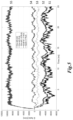
- the first signal S 1 shown in FIG. 5 is the component of the electric field generated in the direction x on the point equidistant between the two plates P 1 and P 2 and in the axis of the same, that is, with coordinates Ex( ⁇ d/2; 0; 0). As can be seen, the signal S 1 has a continuous and an oscillating component.
- the proximity and extension between the plates P 1 and P 2 causes a compensation effect of the charges, which intensifies the internal field of the capacitor and reduces the external one. Furthermore, it is observed that the proximity of the two plates P 1 and P 2 causes the field to oscillate strongly even in the vicinity of the plate P 1 (signal S 15 ). Even in this case, the use of suitable resistive dissipators will allow the damping of these oscillations.
- spark-gap switches which have the ability to withstand currents of several tens of kA with voltages up to MV and response times of less than 100 ps, as shown by the three previous references. These switches can be activated by laser, which allows a very precise absolute synchronization with the initial laser pulse which had allowed the charge to be deposited on the capacitor. Thereby, on command, electric field pulses with fast rising and falling edges and the possibility of being periodic are obtained, using commercially available pulse train lasers for this purpose.
- a “capacitor” which has electrodes with dimensions of a few millimeters can reach electric fields of several hundreds of MV/m and even of GV/m.
- inductive elements only involves the presence of strong sinusoidal oscillations, in connection with shorter rise times however.
- tunable elements in this connection towards ground therefore allows to obtain the rise time performance of the electrostatic fields or the amplitude and frequency of any sinusoidal oscillations which can be changed as needed.
- the structure can be used to supply an electrostatic field with rapid creation/destruction or can be a sinusoidal oscillator with a high amplitude and appropriate frequency, in a manageable manner with relative ease.
- a further use diagram of the methodology concerns the creation of charge pulses with a short time duration, which propagate as waves along a suitable transmission line, as in the diagram in FIG. 8 .
- the laser hits the plate P 1 , connected to a transmission line closed in the characteristic impedance thereof.
- the bunch of charge Q 1 which is created on the plate P 1 propagates in the form of a pseudo-Gaussian pulse towards the end of the transmission line.
- the bunch of charges Q 1 will be in a particular point of the transmission line, and an associated electric field will be located there.
- this methodology can also be used in electrostatic spectrometers, where capacitor structures are used for energy selection. This means being able to activate or not activate an electrostatic spectrometer on command and at very fast times, as well as in a repetitive manner. Furthermore, if the generated charge is sent to a classic electrostatic lens structure, it is possible to obtain the focusing of a beam of charged particles as described in Szilagyi, M. “Electron and ion optics” (Plenum Press, 1988).
Landscapes
- Physics & Mathematics (AREA)
- Engineering & Computer Science (AREA)
- Plasma & Fusion (AREA)
- Spectroscopy & Molecular Physics (AREA)
- Lasers (AREA)
- Particle Accelerators (AREA)
Abstract
Description
- M. Di Giacomo, A. Caruso, G. Gallo, E. Zappalà, D. Rifuggiato, A. Longhitano, F. Consoli, “Measurements of the first prototype of the Spiral2 Single Bunch Selector”, Proceedings of the 3rd International Particle Accelerator Conference, 20-25 May 2012, New Orleans, Louisiana, USA. ISBN 978-3-95450-115-1,
- M. Di Giacomo, P. Balleyguier, F. Consoli, A. Caruso, A. Longhitano, “Experimental determination of impedance and delay time of the 100 ohm meander transmission line for the SPIRAL2 single bunch selector”, Proceedings of the 2nd International Particle Accelerator Conference, 4-9 Sep. 2011, San Sebastian, Spain. “IPAC 2011”, ISBN 978-92-9083-366-6,
- F. Consoli, A. Caruso, G. Gallo, D. Rifuggiato, E. Zappalà, M. Di Giacomo, “RF design of the power coupler for the SPIRAL2 Single Bunch Selector”, Proceedings of 2011 Particle Accelerator Conference, 28 Mar.-1 Apr. 2011, New York, NY, USA, and
- F. Consoli, P. Balleyguier, M. Di Giacomo, “Broadband electromagnetic characterization of a 100 ohm travelling-wave electrode by measuring scattering parameters”, Physical Review Special Topics—Accelerators and Beams Vol, 16, page 072001-1-072001-9, 2013.
- W. Zhang, J. Sandberg, “Pulsed Power Systems in Large Accelerator Complex”, Proceedings of the 3rd Japan-US Symposium on Pulsed Power and Plasma Applications, Kauai, Hawaii, Aug. 6-Aug. 8, 2006;
- Giuseppe Maffia, Alessandro Lampasi, Pietro Zito, “A New Generation of Pulsed Power Supplies for Experimental Physics Based on Supercapacitors”, Proceedings of the 15th IEEE International Conference on Environment and Electrical Engineering (EEEIC), 10-13 Jun. 2015, Rome, Italy, and
- P. D. Pearce, PULSED POWER FOR FUTURE LINEAR ACCELERATORS, Proceedings of the IEE Symposium on Pulsed Power '99 (Digest No. 1999/030), 15-14 Apr. 1999, Pembroke College, Oxford University, UK.
- B. M. Novac et al, “A 10-GW Pulsed Power Supply for HPM Sources”, IEEE TRANSACTIONS ON PLASMA SCIENCE, VOL. 34, NO. 5, October 2006,
- T. Takayanagi et al, “DEVELOPMENT OF A NEW PULSED POWER SUPPLY WITH THE SiC-MOSFET”, Proceedings of 2017 IPAC, Copenhagen, Denmark 2017,
- D. B. Reisman et al, “Pulsed power accelerator for material physics experiments”, Physical review special topics—accelerators and beams 18, 090401 (2015), and
- J. N. Downing et al, “PULSED POWER SYSTEMS FOR THE DARHT ACCELERATORS”, Proceedings of the Eighth IEEE International Pulsed Power Conference, Jun. 17-19, 1991, San Diego, CA.
- Dubois, J.-L. et al., “Target charging in short-pulse-laser-plasma experiments”, Phys. Rev. E 89, 013102 (2014),
- Poyé, A. et al., “Dynamic model of target charging by short laser pulse interactions”, Phys. Rev. E 92, 043107 (2015),
- Poyé, A. et al., “Physics of giant electromagnetic pulse generation in short-pulse laser experiments”, Phys. Rev. E 91, 043106 (2015), and
- Poyé, A. et al., “Thin target charging in short laser pulse interactions”, Physical Review E 98, 033201 (2018).
-
- The solution described herein applies to structures with a considerably different and “multitudinously connected” shape, with much larger dimensions. This allows to have much larger spatial regions affected by the electromagnetic fields generated by the process.
- The suggested structures are suitable for cascading, with electromagnetic field profiles which can be different for each of the cascade structures, in terms of intensity, dimensions of the spatial regions involved and spatial profiles of the field therein (uniform, non-uniform, with profiles designed ad hoc), without this significantly influencing the others in the cascade.
- The use of suitable adjustable or tunable RLC networks allows to obtain both stationary electromagnetic fields with rapid rise time and high-intensity sinusoidal fields.
- The possibility of using structures which are always multiply connected as transmission lines, where a short charge pulse is to be propagated, for example as in the structure shown in
FIG. 7 , which allows the deflection of a particle beam which propagates synchronously and with the same speed as the charge. In the latter case, the methodology shown differs from the disclosure provided in the publication Kar, S. et al., “Guided post-acceleration of laser-driven ions by a miniature modular structure”, Nat. Comm. 7, 10792 (2016). In this publication, in fact, a single laser beam is used to accelerate a beam of charged particles by laser-matter interaction and as a result of the same interaction a neutralization current is obtained (due to the rapid positive charging of the same target) which fed a helix structure, in which a traveling wave allows to focus the previous beam of charged particles. In this case the structure is unique and “simply connected”.
- Krása, J., et al., “Spectral and temporal characteristics of target current and electromagnetic pulse induced by nanosecond laser ablation”, Plasma Phys. Control. Fusion 59, 065007 (2017),
- Cikhardt, J. et al., “Measurement of the target current by inductive probe during laser interaction on terawatt laser system PALS”, Rev. Sci. Instrum. 85, 103507 (2014),
- Santos, J. J. et al., “Laser-driven platform for generation and characterization of strong quasi-static magnetic fields, New J. Phys. 17, 083051 (2015),
- Fujioka, S. et al., “Kilotesla magnetic field due to a capacitor-coil target driven by high power laser”, Sci. Rep. 3, 1170 (2012),
- Law, K. F. F. et al., “Direct measurements of kilo-tesla level magnetic field generated with laser-driven capacitor-coil target by proton deflectometry”, Appl. Phys. Lett. 108, 091104 (2016), and
- Tikhonchuk, V. T., Bally-Grandvaux, M., and Santos J. J., “Quasi stationary magnetic field generation with a laser-driven capacitor-coil assembly”, Phys. Rev. E 96, 023202 (2017).
- F. Consoli et al, EMP characterization at PALS on solid target experiments, Plasma Phys. Control. Fusion 60 (2018) 105006,
- which are the clear indication of a high charge accumulation even in these conditions.
- Brussard, G. J. H., Hendriks, J., “Photoconductive switching of a high-voltage spark gap”, Appl. Phys. Lett. 86, 081503 (2005),
- Hendriks, J., Broks, B. H. P., van der Mullen, J. J. A. M., Brussaard, G. J. H., “Experimental investigation of an atmospheric photoconductively switched high-voltage spark gap”, J. Appl. Phys. 98, 043309 (2005), and
- Schwarz, H. J., Hora H., edts., “Laser interaction and related plasma phenomena”, (Plenum Press, 1971).
E=Q/(S*ε) (1)
-
- 1) the transmission line is formed so as to have the phase velocity of the electromagnetic wave associated with the bunch P1 equal to the drift velocity of the bunch Q2, and
- 2) the two bunches are time synchronized,
- then the field due to the bunch Q1 will be temporally synchronized with the bunch Q2 for the whole duration of the propagation of both along the transmission line. The field generated by Q1 will therefore affect Q2 for the entire crossing of the transmission line, deflecting Q2 in the meantime which moves therein. This technique is particularly efficient for high-energy Q2 bunches, where the classic capacitor deflector is not sufficiently effective. The difficulty, however, is to have bunches Q1 of high charge, short duration and periodically available. All features easily obtainable if this charge is obtained by the laser-matter interaction process described above.
-
- stationary with rapid rise time,
- high intensity sinusoidal, and
- traveling wave.
- Gupta, K. M., Gupta, N., “Advanced electrical and electronics materials: processes and applications”, (Wiley, 2015),
- Nalwa, H. S., edt. “Handbook of low and high dielectric constant materials and their applications”, (Academic Press, 1999)
- Ott, H. W., “Electromagnetic compatibility engineering”, (John Wiley & Sons, 2009) or for general studies of electromagnetic compatibility, as explained in Ott, as well as in advanced structures, which generate terahertz radiation, as indicated in Houard, A, et al, A. “Strong Enhancement of Terahertz Radiation from Laser Filaments in Air by a Static Electric Field”, Phys. Rev. Lett. 100, 255006 (2008) e in Singh, R. K., Kumar, S. & Sharma R. P., “Generation of electromagnetic waves in the terahertz frequency range by optical rectification of a Gaussian laser pulse in a plasma in presence of an externally applied static electric field”, Contrib. Plasma Phys. 57, 252 (2017).
Claims (9)
Applications Claiming Priority (3)
| Application Number | Priority Date | Filing Date | Title |
|---|---|---|---|
| IT102019000014385A IT201900014385A1 (en) | 2019-08-08 | 2019-08-08 | METHOD OF GENERATION OF HIGH INTENSITY ELECTROMAGNETIC FIELDS |
| IT102019000014385 | 2019-08-08 | ||
| PCT/IB2020/057464 WO2021024226A1 (en) | 2019-08-08 | 2020-08-07 | Method for generating high intensity electromagnetic fields |
Publications (2)
| Publication Number | Publication Date |
|---|---|
| US20220287171A1 US20220287171A1 (en) | 2022-09-08 |
| US12267943B2 true US12267943B2 (en) | 2025-04-01 |
Family
ID=69024519
Family Applications (1)
| Application Number | Title | Priority Date | Filing Date |
|---|---|---|---|
| US17/632,674 Active 2041-10-24 US12267943B2 (en) | 2019-08-08 | 2020-08-07 | Method for generating high intensity electromagnetic fields |
Country Status (4)
| Country | Link |
|---|---|
| US (1) | US12267943B2 (en) |
| EP (1) | EP4011178A1 (en) |
| IT (1) | IT201900014385A1 (en) |
| WO (1) | WO2021024226A1 (en) |
Families Citing this family (2)
| Publication number | Priority date | Publication date | Assignee | Title |
|---|---|---|---|---|
| US11632179B1 (en) * | 2022-03-15 | 2023-04-18 | United States Of America As Represented By The Secretary Of The Navy | Remotely emitting confined electromagnetic radiation from laser-induced plasma filaments |
| CN116507010B (en) * | 2023-05-15 | 2026-01-30 | 北京大学 | A controllable microwave source based on a laser accelerator and its control method |
Citations (1)
| Publication number | Priority date | Publication date | Assignee | Title |
|---|---|---|---|---|
| US20080191143A1 (en) * | 2005-03-16 | 2008-08-14 | Oswald Willi | Laser Irradiated Hollow Cylinder Serving as a Lens for Ion Beams |
-
2019
- 2019-08-08 IT IT102019000014385A patent/IT201900014385A1/en unknown
-
2020
- 2020-08-07 WO PCT/IB2020/057464 patent/WO2021024226A1/en not_active Ceased
- 2020-08-07 EP EP20765355.1A patent/EP4011178A1/en active Pending
- 2020-08-07 US US17/632,674 patent/US12267943B2/en active Active
Patent Citations (1)
| Publication number | Priority date | Publication date | Assignee | Title |
|---|---|---|---|---|
| US20080191143A1 (en) * | 2005-03-16 | 2008-08-14 | Oswald Willi | Laser Irradiated Hollow Cylinder Serving as a Lens for Ion Beams |
Non-Patent Citations (7)
| Title |
|---|
| Consoli et al., Generation of Intense Quasi-Electrostatic Fields Due To Deposition of Particles Accelerated by Petawatt-Range Laser-Matter Interactions, Scientific Reports, vol. 9, No. 1, Jun. 12, 2019, 14 pages. |
| Geng et al., Dual-Frequency Brillouin Fiber Laser for Optical Generation of Tunable Low-Noise Radio Frequency/Microwave Frequency, 2008, Optics Letters, vol. 33, No. 1, pp. 16-18. (Year: 2008). * |
| International Search Report and Written Opinion Received for the PCT Application No. PCT/IB2020/057464, mailed on Nov. 4, 2020, 15 pages. |
| Kar et al., Dynamic Control of Laser-Produced Proton Beams, Physical Review Letters, vol. 100, No. 10, Mar. 14, 2008, 4 pages. |
| Kar et al., Guided Post-Acceleration of Laser-Driven lons by a Miniature Modular Structure, Nature Communications, vol. 7, No. 1, Apr. 18, 2016, 7 pages. |
| Zhai et al., Proton Array Focused by a Laser-Irradiated Mesh, 2019, Appl. Phys. Lett. 114, 013509. (Year: 2019). * |
| Zhai et al., Proton Array Focused By A Laser-Irradiated Mesh, Applied Physics Letters, AIP Publishing LLC, vol. 114, No. 1, Jan. 8, 2019, 5 pages. |
Also Published As
| Publication number | Publication date |
|---|---|
| WO2021024226A1 (en) | 2021-02-11 |
| IT201900014385A1 (en) | 2021-02-08 |
| US20220287171A1 (en) | 2022-09-08 |
| EP4011178A1 (en) | 2022-06-15 |
Similar Documents
| Publication | Publication Date | Title |
|---|---|---|
| EP2158796B1 (en) | Beam transport system and method for linear accelerators | |
| US7576499B2 (en) | Sequentially pulsed traveling wave accelerator | |
| US7710051B2 (en) | Compact accelerator for medical therapy | |
| US5811944A (en) | Enhanced dielectric-wall linear accelerator | |
| US5757146A (en) | High-gradient compact linear accelerator | |
| Zhang et al. | Experimental study on conduction current of positive nanosecond-pulse diffuse discharge at atmospheric pressure | |
| US12267943B2 (en) | Method for generating high intensity electromagnetic fields | |
| Cadilhon et al. | Low-stray inductance structure to improve the rise-time of a Marx generator | |
| US8466429B2 (en) | Particle beam injector system and method | |
| CN101406110B (en) | Sequentially pulsed traveling wave accelerator | |
| Persaud et al. | A compact linear accelerator based on a scalable microelectromechanical-system RF-structure | |
| Dyson et al. | A compact, low cost Marx bank for generating capillary discharge plasmas | |
| Yalandin et al. | A picosecond-jitter electron-beam-triggered high-voltage gas spark gap | |
| Vintizenko | Linear induction accelerators for high-power microwave devices | |
| Masugata et al. | Development of bipolar-pulse accelerator for intense pulsed ion beam acceleration | |
| Brussaard et al. | A 2.5-MV subnanosecond pulser with laser-triggered spark gap for the generation of high-brightness electron bunches | |
| Husson et al. | An antiproton deceleration device for the GBAR experiment at CERN | |
| van Oorschot et al. | Fast & flexible impendance-matched solid-state marx generator for paw generation | |
| Romanov | PIC Simulations of One-side Multipactor on Dielectric | |
| Persaud et al. | Ion acceleration in a scalable mems rf-structure for a compact linear accelerator | |
| RU2643175C1 (en) | Method for obtaining pulses of braking radiation with complex amplitude-temporary parameters and device for its implementation | |
| Zhao et al. | A 216 cables synchronization trigger for linear transformer driver | |
| Anderson et al. | Antenna Beam Focusing and Steering with Refraction Through a Plasma with Corresponding Circuitry | |
| Kim et al. | Design Study for Pulsed Proton Beam Generation | |
| Tomisawa et al. | Energy and current waveforms of an intense electron beam passing through cavities |
Legal Events
| Date | Code | Title | Description |
|---|---|---|---|
| AS | Assignment |
Owner name: ENEA AGENZIA NAZIONALE PER LE NUOVE TECNOLOGIE, L'ENERGIA E LO SVILUPPO ECONOMICO SOSTENIBILE, ITALY Free format text: ASSIGNMENT OF ASSIGNORS INTEREST;ASSIGNORS:CONSOLI, FABRIZIO;DE ANGELIS, RICCARDO;ANDREOLI, PIERLUIGI;AND OTHERS;REEL/FRAME:058880/0145 Effective date: 20200915 |
|
| FEPP | Fee payment procedure |
Free format text: ENTITY STATUS SET TO UNDISCOUNTED (ORIGINAL EVENT CODE: BIG.); ENTITY STATUS OF PATENT OWNER: SMALL ENTITY |
|
| FEPP | Fee payment procedure |
Free format text: ENTITY STATUS SET TO SMALL (ORIGINAL EVENT CODE: SMAL); ENTITY STATUS OF PATENT OWNER: SMALL ENTITY |
|
| STPP | Information on status: patent application and granting procedure in general |
Free format text: DOCKETED NEW CASE - READY FOR EXAMINATION |
|
| STPP | Information on status: patent application and granting procedure in general |
Free format text: NON FINAL ACTION MAILED |
|
| STPP | Information on status: patent application and granting procedure in general |
Free format text: RESPONSE TO NON-FINAL OFFICE ACTION ENTERED AND FORWARDED TO EXAMINER |
|
| STPP | Information on status: patent application and granting procedure in general |
Free format text: NOTICE OF ALLOWANCE MAILED -- APPLICATION RECEIVED IN OFFICE OF PUBLICATIONS |
|
| STPP | Information on status: patent application and granting procedure in general |
Free format text: PUBLICATIONS -- ISSUE FEE PAYMENT VERIFIED |
|
| STCF | Information on status: patent grant |
Free format text: PATENTED CASE |