US12267142B2 - Forming a beam from a subscriber module of a fixed wireless access communication system - Google Patents
Forming a beam from a subscriber module of a fixed wireless access communication system Download PDFInfo
- Publication number
- US12267142B2 US12267142B2 US18/310,313 US202318310313A US12267142B2 US 12267142 B2 US12267142 B2 US 12267142B2 US 202318310313 A US202318310313 A US 202318310313A US 12267142 B2 US12267142 B2 US 12267142B2
- Authority
- US
- United States
- Prior art keywords
- beams
- antenna
- curved row
- row
- array
- Prior art date
- Legal status (The legal status is an assumption and is not a legal conclusion. Google has not performed a legal analysis and makes no representation as to the accuracy of the status listed.)
- Active
Links
- 238000004891 communication Methods 0.000 title claims abstract description 31
- 239000013598 vector Substances 0.000 claims abstract description 52
- 238000012886 linear function Methods 0.000 claims abstract description 7
- 238000000034 method Methods 0.000 claims description 32
- 230000008859 change Effects 0.000 claims description 8
- 230000003121 nonmonotonic effect Effects 0.000 claims description 4
- 230000010363 phase shift Effects 0.000 claims 2
- 238000000926 separation method Methods 0.000 description 13
- 230000008569 process Effects 0.000 description 11
- 238000003491 array Methods 0.000 description 7
- 238000010586 diagram Methods 0.000 description 7
- 230000005540 biological transmission Effects 0.000 description 6
- 230000000694 effects Effects 0.000 description 4
- 230000006872 improvement Effects 0.000 description 4
- 238000013459 approach Methods 0.000 description 3
- 230000001419 dependent effect Effects 0.000 description 3
- 230000008901 benefit Effects 0.000 description 2
- 239000002184 metal Substances 0.000 description 2
- 230000005855 radiation Effects 0.000 description 2
- 230000009467 reduction Effects 0.000 description 2
- 238000010521 absorption reaction Methods 0.000 description 1
- 230000002411 adverse Effects 0.000 description 1
- QVGXLLKOCUKJST-UHFFFAOYSA-N atomic oxygen Chemical compound [O] QVGXLLKOCUKJST-UHFFFAOYSA-N 0.000 description 1
- 230000009286 beneficial effect Effects 0.000 description 1
- 230000015572 biosynthetic process Effects 0.000 description 1
- 238000004364 calculation method Methods 0.000 description 1
- 239000000919 ceramic Substances 0.000 description 1
- 238000013461 design Methods 0.000 description 1
- 230000006870 function Effects 0.000 description 1
- 238000009434 installation Methods 0.000 description 1
- 239000000463 material Substances 0.000 description 1
- 238000012986 modification Methods 0.000 description 1
- 230000004048 modification Effects 0.000 description 1
- 230000003287 optical effect Effects 0.000 description 1
- 229910052760 oxygen Inorganic materials 0.000 description 1
- 239000001301 oxygen Substances 0.000 description 1
- 238000012856 packing Methods 0.000 description 1
- 238000012545 processing Methods 0.000 description 1
- 239000000758 substrate Substances 0.000 description 1
- 238000010408 sweeping Methods 0.000 description 1
Images


Classifications
-
- H—ELECTRICITY
- H04—ELECTRIC COMMUNICATION TECHNIQUE
- H04B—TRANSMISSION
- H04B7/00—Radio transmission systems, i.e. using radiation field
- H04B7/02—Diversity systems; Multi-antenna system, i.e. transmission or reception using multiple antennas
- H04B7/04—Diversity systems; Multi-antenna system, i.e. transmission or reception using multiple antennas using two or more spaced independent antennas
- H04B7/06—Diversity systems; Multi-antenna system, i.e. transmission or reception using multiple antennas using two or more spaced independent antennas at the transmitting station
- H04B7/0613—Diversity systems; Multi-antenna system, i.e. transmission or reception using multiple antennas using two or more spaced independent antennas at the transmitting station using simultaneous transmission
- H04B7/0615—Diversity systems; Multi-antenna system, i.e. transmission or reception using multiple antennas using two or more spaced independent antennas at the transmitting station using simultaneous transmission of weighted versions of same signal
- H04B7/0617—Diversity systems; Multi-antenna system, i.e. transmission or reception using multiple antennas using two or more spaced independent antennas at the transmitting station using simultaneous transmission of weighted versions of same signal for beam forming
-
- H—ELECTRICITY
- H04—ELECTRIC COMMUNICATION TECHNIQUE
- H04B—TRANSMISSION
- H04B7/00—Radio transmission systems, i.e. using radiation field
- H04B7/02—Diversity systems; Multi-antenna system, i.e. transmission or reception using multiple antennas
- H04B7/04—Diversity systems; Multi-antenna system, i.e. transmission or reception using multiple antennas using two or more spaced independent antennas
- H04B7/08—Diversity systems; Multi-antenna system, i.e. transmission or reception using multiple antennas using two or more spaced independent antennas at the receiving station
- H04B7/0837—Diversity systems; Multi-antenna system, i.e. transmission or reception using multiple antennas using two or more spaced independent antennas at the receiving station using pre-detection combining
- H04B7/0842—Weighted combining
- H04B7/086—Weighted combining using weights depending on external parameters, e.g. direction of arrival [DOA], predetermined weights or beamforming
-
- H—ELECTRICITY
- H01—ELECTRIC ELEMENTS
- H01Q—ANTENNAS, i.e. RADIO AERIALS
- H01Q19/00—Combinations of primary active antenna elements and units with secondary devices, e.g. with quasi-optical devices, for giving the antenna a desired directional characteristic
- H01Q19/10—Combinations of primary active antenna elements and units with secondary devices, e.g. with quasi-optical devices, for giving the antenna a desired directional characteristic using reflecting surfaces
- H01Q19/12—Combinations of primary active antenna elements and units with secondary devices, e.g. with quasi-optical devices, for giving the antenna a desired directional characteristic using reflecting surfaces wherein the surfaces are concave
- H01Q19/17—Combinations of primary active antenna elements and units with secondary devices, e.g. with quasi-optical devices, for giving the antenna a desired directional characteristic using reflecting surfaces wherein the surfaces are concave the primary radiating source comprising two or more radiating elements
-
- H—ELECTRICITY
- H01—ELECTRIC ELEMENTS
- H01Q—ANTENNAS, i.e. RADIO AERIALS
- H01Q19/00—Combinations of primary active antenna elements and units with secondary devices, e.g. with quasi-optical devices, for giving the antenna a desired directional characteristic
- H01Q19/10—Combinations of primary active antenna elements and units with secondary devices, e.g. with quasi-optical devices, for giving the antenna a desired directional characteristic using reflecting surfaces
- H01Q19/18—Combinations of primary active antenna elements and units with secondary devices, e.g. with quasi-optical devices, for giving the antenna a desired directional characteristic using reflecting surfaces having two or more spaced reflecting surfaces
- H01Q19/19—Combinations of primary active antenna elements and units with secondary devices, e.g. with quasi-optical devices, for giving the antenna a desired directional characteristic using reflecting surfaces having two or more spaced reflecting surfaces comprising one main concave reflecting surface associated with an auxiliary reflecting surface
- H01Q19/192—Combinations of primary active antenna elements and units with secondary devices, e.g. with quasi-optical devices, for giving the antenna a desired directional characteristic using reflecting surfaces having two or more spaced reflecting surfaces comprising one main concave reflecting surface associated with an auxiliary reflecting surface with dual offset reflectors
-
- H—ELECTRICITY
- H01—ELECTRIC ELEMENTS
- H01Q—ANTENNAS, i.e. RADIO AERIALS
- H01Q3/00—Arrangements for changing or varying the orientation or the shape of the directional pattern of the waves radiated from an antenna or antenna system
- H01Q3/12—Arrangements for changing or varying the orientation or the shape of the directional pattern of the waves radiated from an antenna or antenna system using mechanical relative movement between primary active elements and secondary devices of antennas or antenna systems
- H01Q3/16—Arrangements for changing or varying the orientation or the shape of the directional pattern of the waves radiated from an antenna or antenna system using mechanical relative movement between primary active elements and secondary devices of antennas or antenna systems for varying relative position of primary active element and a reflecting device
- H01Q3/20—Arrangements for changing or varying the orientation or the shape of the directional pattern of the waves radiated from an antenna or antenna system using mechanical relative movement between primary active elements and secondary devices of antennas or antenna systems for varying relative position of primary active element and a reflecting device wherein the primary active element is fixed and the reflecting device is movable
-
- H—ELECTRICITY
- H04—ELECTRIC COMMUNICATION TECHNIQUE
- H04B—TRANSMISSION
- H04B7/00—Radio transmission systems, i.e. using radiation field
- H04B7/02—Diversity systems; Multi-antenna system, i.e. transmission or reception using multiple antennas
- H04B7/04—Diversity systems; Multi-antenna system, i.e. transmission or reception using multiple antennas using two or more spaced independent antennas
- H04B7/08—Diversity systems; Multi-antenna system, i.e. transmission or reception using multiple antennas using two or more spaced independent antennas at the receiving station
- H04B7/0882—Diversity systems; Multi-antenna system, i.e. transmission or reception using multiple antennas using two or more spaced independent antennas at the receiving station using post-detection diversity
- H04B7/0888—Diversity systems; Multi-antenna system, i.e. transmission or reception using multiple antennas using two or more spaced independent antennas at the receiving station using post-detection diversity with selection
Definitions
- the present invention relates to a subscriber module of a fixed wireless access communication system, the subscriber module comprising an offset Gregorian antenna arrangement comprising a primary reflector dish and a secondary reflector and an array of antenna elements arranged as a feed for the secondary reflector, and to a method of forming a beam from the subscriber module.
- an array of antenna elements may be conventionally provided in which the amplitude and/or phase of each antenna element is controlled by a beamformer to produce beams.
- the gain of a beam provided by the array of antenna elements may be limited by the number of elements in the array. It may be required to produce beams having a greater gain than may be provided by a given array.
- a subscriber module of a fixed wireless access communication system comprising:
- Providing the offset Gregorian antenna arrangement provides a convenient method of increasing the gain of beams provided by the array of antenna elements. Offsetting the secondary reflector in a vertical axis with respect to a centre of the primary reflector dish allows beams to be formed over a broad range of azimuth angles without obstruction of the beam by the secondary reflector or the array. Providing a predetermined plurality of weight vectors is computationally efficient, by allowing the calculation of the weight vectors to be performed in advance of forming the beams.
- Arranging the orientations of the plurality of beams in a grid comprising a plurality of rows allows series of beams to be formed at different azimuth angles and at the same elevation, which allows a convenient method of forming trial beams, for example to establish initial communication between the subscriber module and an access point of the wireless communication system. This also allows a convenient method for re-selection of beams to track movement of a subscriber module due to wind loading, for example if the subscriber module is mounted on a pole above a subscriber's premises.
- Providing the predetermined plurality of weight vectors such that the relationship between the azimuth and elevation direction of each feed beam and the azimuth and elevation direction of the respective beam from the primary reflector dish as a non-linear function of azimuth and elevation allows the plurality of beams formed from the subscriber module to be arranged as a series of straight rows in a grid, by arranging the feed beams from the array of antenna elements as a distorted grid. This allows the processor to apply a simple algorithm to steer beams by selection of beams in a straight row.
- the pre-determined plurality of antenna weight vectors is configured to form the plurality of feed beams such that the orientations of the plurality of beams is arranged in a distorted grid comprising a plurality of curved rows, each curved row providing a monotonic change in azimuth angle along the curved row, and a non-monotonic change in elevation angle along the curved row.
- Each curved row may have an offset in elevation angle between the centre of the curved row and either end of the curved row.
- the offset in elevation angle for a curved row may be equal to the angular spacing in elevation, at the centre of the curved row, between the curved row and an adjacent curved row +/ ⁇ 50%.
- each curved row may have a greater elevation angle at the centre of the curved row than at either end of the curved row.
- each curved row has an approximately parabolic dependence of elevation angle on azimuth angle, within +/ ⁇ 50% of a true parabola.
- the array of antenna elements has 8 element columns and 8 element rows with a spacing between antenna elements in each element row and in each element column of substantially half a wavelength at an operating frequency of the wireless communication system.
- a method of forming a beam from a subscriber module of a fixed wireless access communication system the subscriber module having an offset Gregorian antenna system comprising a primary reflector dish, a secondary reflector, an array of antenna elements and a beamforming network, the beamforming network being configured to form a beam using an antenna weight vector selected from a pre-determined plurality of antenna weight vectors, wherein the array of antenna elements is arranged to feed the secondary reflector to form the beam from the primary reflector dish, the method comprising:
- FIG. 1 is a schematic diagram showing a wireless communication system having an access point and subscriber modules each having an array of antenna elements;
- FIG. 2 shows a first wireless station configured to form a plurality of beams
- FIG. 3 shows a first and second wireless station each configured to form a plurality of beams
- FIG. 4 a shows a wireless station having an array of antenna elements and a beamformer
- FIG. 4 b shoes the array of antenna elements of FIG. 4 b;
- FIG. 5 shows a rectangular grid of pre-configured antenna beams
- FIG. 6 shows an antenna plot of the rectangular grid of antenna beams of FIG. 5 ;
- FIG. 7 shows a detail of FIG. 6 ;
- FIG. 8 shows a grid of pre-configured beams in a triangular arrangement
- FIG. 9 shows an antenna gain plot of the triangular grid of FIG. 8 ;
- FIG. 10 shows a detail of FIG. 9 ;
- FIG. 11 shows an antenna gain plot of the triangular grid of a subset of beams of FIG. 8 , formed by a sub-set of the pre-determined plurality of antenna weight vectors;
- FIG. 12 shows a grid of pre-configured beams in a triangular arrangement having spacing on a row in proportion to beamwidth
- FIG. 13 shows an antenna gain plot of the grid of FIG. 12 ;
- FIG. 14 is a schematic diagram showing the principle of operation of an offset Gregorian antenna arrangement with a planar array of antenna elements as a feed;
- FIG. 15 shows a plurality of feed beams formed to feed a secondary reflector of an offset Gregorian antenna arrangement
- FIG. 16 shows a schematic diagram of a cross-section of the offset Gregorian antenna arrangement
- FIGS. 17 a and 17 b are schematic diagrams showing the shape the primary reflector dish and the secondary reflector in a cross-section in a vertical and horizontal cross-section respectively;
- FIG. 18 shows an oblique perspective view of a first wireless station having the offset Gregorian antenna arrangement
- FIG. 19 is a plan view of the first wireless station, viewed from the direction of a radiofrequency main beam which the offset Gregorian antenna arrangement is configured to form;
- FIG. 20 shows a grid of a plurality of pre-configured beams formed from the primary reflector of an offset Gregorian antenna arrangement
- FIG. 21 is an antenna plot of the grid of FIG. 20 ;
- FIG. 22 shows a plurality of feed beams from the array of antenna elements as a feed to the secondary reflector of a Gregorian antenna system
- FIG. 23 is a flow diagram of a method according to an example.
- Examples of the invention are described in the context of a terrestrial fixed wireless access wireless communication system operating in the band of 57-66 GHz operating according to IEEE 802.11ay.
- the wireless communication system is a time division duplex wireless system.
- embodiments of the invention may relate to other applications, and to other frequency bands.
- FIG. 1 shows a wireless communication system having an access point 1 and subscriber modules 2 a , 2 b , 2 c , 3 a , 3 b , in a schematic plan view.
- the access point 1 as shown covers two sectors, having two planar arrays of antenna elements 4 , 5 arranged to cover a first sector, and two further antenna arrays 6 , 7 arranged to cover a second sector.
- Each of the arrays is arranged to form beams within approximately +/ ⁇ 40 degrees in azimuth and +/ ⁇ 20 degrees in elevation of the bore sight direction of the array, that is to say perpendicular to the plane of the array.
- the two arrays covering a sector are arranged to have boresight directions which are different by approximately 80 degrees, so that beams may be formed in a continuous angular sector of approximately 160 degrees using the two arrays.
- Each element of the array of antenna elements is connected to a beamformer, which may be in the form of a commercially available beamforming radiofrequency integrated circuit arranged to apply a selected weighting vector comprising a respective transmission phase for each element of the array.
- the array of antenna elements may be an 8 ⁇ 8 array of patch antenna elements spaced apart by approximately a half wavelength.
- the beamformer may be typically arranged to form a beam selected from a number of pre-configured beams, in an example 120 pre-configured beams.
- the pre-configured beams may be distributed over an angular sector of approximately +/ ⁇ 40 degrees in azimuth and +/ ⁇ 20 degrees in elevation.
- the access point 1 is typically located on a tower, and the subscriber modules may be a mix of high gain 3 a , 3 b and lower gain 2 a , 2 b , 2 c subscriber modules, typically fixed to poles mounted at subscribers' premises, which may be commercial or private residential premises, for example.
- the lower gain subscriber module 2 a , 2 b , 2 c have an antenna arrangement comprising a similar array of antenna elements to that used at the access point, and may be installed relatively close to the access point, typically within a few hundred metres.
- the high gain subscriber modules 3 a , 3 b have an antenna arrangement comprising a similar or the same array of antenna elements to that used at the access point, but the array is used as a feed for an offset Gregorian antenna arrangement, which gives an improved antenna gain and a narrower antenna beam,
- the array of antenna elements may be the same 8 ⁇ 8 array of patch antenna elements used at the access point, and the beamformer may also be arranged to form a beam selected from 120 pre-configured beams distributed over an angular sector of approximately +/ ⁇ 40 degrees in azimuth and +/ ⁇ 20 degrees in elevation in one example.
- the lower gain subscriber module 2 a , 2 b , 2 c is aligned roughly in the direction of the access point, and the best beam for use can be selected by a sweep of possible beams at the subscriber module also sweeping possible beams at the access point, which my be an exhaustive search of each combination of beams, so that a best beam at the subscriber module and a best beam at the access point can be selected.
- the higher gain subscriber modules 3 a , 3 b may be installed further from the access point, for example at distances of 1 km or more.
- the higher gain antenna arrangement may overcome the greater signal loss due the greater propagation distance and the effects of signal loss due to oxygen absorption and rain in the approximately 60 GHz band.
- the high gain subscriber modules 3 a , 3 b typically use the same array of antenna elements and the same beamforming arrangement as used at the access point 1 and the lower gain subscriber modules 2 a , 2 b , 2 c , as a feed for the offset Gregorian antenna system.
- the beam produced by the array of antenna elements is reflected by the secondary reflector of the offset Gregorian antenna system onto the primary reflector dish, to produce a narrower beam from the primary reflector dish than the beam produced by the array.
- the beam produced by the array may be approximately +/ ⁇ 8 degrees between 3 dB points and the beam transmitted or received by the primary reflector dish may be approximately 0.7 degrees between 3 dB points.
- the overall gain of the antenna arrangement of the high gain subscriber module may be approximately 44 dBi (deciBels compared to isotropic) for this arrangement.
- the high gain antenna arrangement results in a reduction in the angular sector over which a beam may be formed.
- the pre-configured beams may be distributed over an angular sector of approximately +/ ⁇ 2 degrees in azimuth and +/ ⁇ 1 degree in elevation from the primary reflector dish. The same technique of using a scan of the beams at the access point and the subscriber module is used to find a best beam, as for the lower gain subscriber modules.
- an optical sight attached to the high gain subscriber module is typically used to first of all install the subscriber module in an orientation in which the angular sector over which the beams may be steered includes the direction of the access point.
- FIG. 2 shows a first wireless station 8 , which may be a subscriber module or an access point, configured to form a plurality of beams 10 using an array of antenna elements 13 , and a second wireless station 9 , typically the other of the access point and the subscriber module, configured to form a fixed beam 11 .
- first wireless station 8 performs the sweep to first beam.
- FIG. 3 shows a first 8 and second 9 wireless station each configured to form a plurality of beams, 10 , 12 .
- the first wireless station may be a subscriber module and the second wireless station may be an access point.
- more than one access point may be used to form a meshed communication system.
- the first 8 and second 9 wireless stations may both be access points, and each will select a best beam for use by a search process as already described.
- FIG. 4 a shows a wireless station, which may be the first and/or the second wireless station.
- the wireless station has an array of antenna elements 22 and a beamformer 23 .
- FIG. 4 b shows that the array of antenna elements 22 comprises a two dimensional planar array of elements.
- the antenna elements may be conventional patch antenna elements formed by conductive metal film carried on a non-conductive substrate such as a ceramic tile or conventional printed circuit board material.
- Two, or more, planar arrays may be arranged with different boresight directions in azimuth in order to allow beams to be formed over a larger angular sector.
- the beamformer applies a weighting to the signal transmitted and/or received by each antenna element. Typically, the weighting is a transmission phase value.
- the transmission phase value is typically quantised, for example to allow switching by 90 degree steps.
- the application of the transmission phase value to the signal may be implemented by use of a switchable transmission delay.
- a combiner/splitter tree connects each element of the beamformer via a frequency converter stage to a radio modulator/demodulator 25 , to convert received signals and/or signals for transmission to and from digital format.
- a processor and controller 26 controls the beam selection and acquisition stage. Pre-configured beams are stored in memory 24 , for application to the beamformer 23 under control of the processor 26 .
- the processor may be implemented using conventional digital techniques, and may be implemented in software, firmware or cloud-based processing. The formation of beams using phase weights applied to signals received by and/or transmitted by antenna elements is well known in the art.
- a beam with a conventional sine function beam shape may be formed by applying weights the antenna elements with uniform gain and with an appropriate phase slope across the array in each dimension to steer the beam in the desired direction.
- the antenna array and beamformer may be commercially available items, for example the Samsung SWL-QD46 module.
- FIG. 5 shows that the pre-determined plurality of antenna weight vectors may be configured to form a plurality of beams 35 a , 35 b , etc, the orientations of the plurality of beams being arranged in a rectangular grid.
- the reference numerals are shown as examples on only a few beams for clarity, but each of the beams shown is one of the plurality beams.
- This approach allows a search of beams for acquisition using a conventional search in a two-dimensional plane arranged as rows and columns as shown. By this approach, may be easily searched by incrementation of an index in each orthogonal dimension, typically in azimuth and elevation.
- FIG. 6 shows a plot of antenna gain for the beam arrangement of FIG. 5 , showing the maximum gain that can be achieved at each point in the grid by selection of the best beam.
- FIG. 7 shows part of FIG. 6 in more detail. It can be seen that, in the troughs 36 between peaks of beams 35 , the gain is approximately 2.4 dB below that of the peaks of the beams. The contours are in steps of 0.2 dB.
- FIG. 8 shows that the pre-determined plurality of antenna weight vectors may be configured to form a plurality of beams 27 a , 27 b , etc., the orientations of the plurality of beams being arranged in an arrangement of equilateral triangles.
- the reference numerals are shown as examples on only a few beams for clarity, but each of the beams shown is one of the plurality beams, that is to say each of the beams numbered 1-120.
- the numbers in circles 28 a , 28 b , etc. are beams in the first subset of the plurality of beams used for an initial search and the numbers in squares 39 a , 39 b , etc., are beams in the second subset of the plurality of beams used for a refined search once a first beam, in this example beam number 66, that can allow communication the second station has been determined.
- the beams of each row are spaced in angular position in the row on a first axis 32 , such that at least one beam in a respective row is positioned mid-way on the first axis between the positions on the first axis of two beams on an adjacent row.
- beam number 22 in row 34 b is mid-way on the azimuth axis 32 between beam numbers 9 and 10 in row 34 a.
- FIG. 9 shows a plot of antenna gain for the beam arrangement of FIG. 8 , showing the maximum gain that can be achieved at each point in the arrangement by selection of the best beam.
- FIG. 10 shows part of FIG. 9 in more detail. The contours are in steps of 0.2 dB. It can be seen that, in the troughs 37 between peaks of beams 27 , the gain is approximately 1.8 dB below that of the peaks of the beams. This arrangement gives an improvement over the rectangular arrangement of FIG. 5 of about 0.6 dB in the minimum gain available. This improvement provides addition link margin to allow communication and acquisition in adverse atmospheric conditions.
- the first station has an antenna comprising an array of antenna elements and a beamforming network, the beamforming network being configured to form a beam using an antenna weight vector selected from a pre-determined plurality of antenna weight vector.
- the pre-determined plurality of antenna weight vectors may be referred to as a codebook.
- the pre-determined plurality of antenna weight vectors are configured to form a plurality of beams.
- the position of each of the plurality of beams is shown overlaid as illustrated in FIG. 8 .
- the orientations of the beams are arranged in a grid comprising a plurality of rows 34 a , 34 b , etc., the beams of each row being spaced in angular position in the row by a first angular separation 29 on a first axis 32 , in this example azimuth.
- the angular positions of the beams of each row is offset 30 on the first axis 32 by half of the first angular separation 29 with respect to the angular positions of beams in an adjacent row.
- each beam 27 a , 27 a , etc., in row 34 a is offset by half the separation between beams 29 with respect to the angular positions of beams in an adjacent row 34 b .
- the beam numbers 1-120 shown in FIG. 8 are arbitrary.
- each row is separated from an adjacent row by the first angular separation 29 multiplied by cosine 30 degrees on a second axis, perpendicular to the first axis 32 , so that each beam of the plurality of beams is arranged as an equilateral triangle with two adjacent beams.
- row 34 a is separated from row 34 b by the first angular separation 29 multiplied by cosine 30 degrees.
- the positions of the beams will be subject to errors due to the accuracy of the beamforming weights, taking into account the effects of quantisation.
- a first sub-set of the pre-determined plurality of antenna weight vectors is selected, as shown as circled beams 28 a , 28 b , etc.
- 30 beams are selected for the sub-set, being 1 in 4 beams.
- FIG. 11 shows an antenna gain plot of the triangular grid of the subset of beams 28 c , 28 d , etc., formed by a sub-set of the pre-determined plurality of antenna weight vectors.
- the sub-set which is referred to as the first sub-set, is selected to form selected beams on alternate rows of the grid, the selected beams of each alternate row being spaced in angular position on the first axis by twice the first angular separation, and the angular position of the selected beams of each alternate row being offset on the first axis by the first angular separation. This arranges each selected beam in the subset as an equilateral triangle with two adjacent selected beams.
- This arrangement provides a minimum gain between peaks of beams in the sub-set of approximately ⁇ 5.5 dB. This gives an improvement in link margin for initial acquisition compared with the minimum gain between peaks for a rectangular grid of beams because of the tighter packing of the triangular arrangement.
- another proportion of the beams may be selected for the sub-set other than 1 in 4, for example 1 in 9 beams.
- a triangular arrangement shows an advantage.
- a succession of beams is formed in a first time sequence at the first station using the first sub-set of the pre-determined plurality of antenna weight vectors to send first messages.
- a refined search is carried out using a further succession of beams is formed at the first station using a second sub-set of the pre-determined plurality of antenna weight vectors selected to form beams adjacent to the first beam.
- the second sub-set is selected to form at least a ring of six beams surrounding the respective first and second beams if the first or second beam is not at an edge of the grid.
- the second sub-set of beams is shown in FIG. 8 by the beams marked by squares, 39 a , 39 b , etc., which surround the first beam 38 which was selected in the initial acquisition process. This provides an efficient process for selecting a best beam for use after establishing initial communication.
- the array of antenna elements of the first station may be arranged to feed a secondary reflector of an offset Gregorian antenna arrangement, to increase the antenna gain. This may be beneficial for a subscriber module, an access point, or for a wireless station arranged in a mesh arrangement where more gain is required.
- FIG. 12 shows an alternative arrangement of the grid of pre-configured beams in a triangular arrangement having spacing on a row in proportion to beamwidth. It can be seen that beams at the centre of a row 27 f , 27 g have a closer angular spacing than beams towards the end of a row 27 h , 27 i .
- the spacing is constant in terms of a proportion of the 3 dB beamwidth of a beam. This may provide a means of reducing the number of beams which need to be searched in an acquisition process. The reduction of gain between the areas between beams may be kept approximately constant across the grid of beams by this approach.
- FIG. 13 shows an antenna gain plot of the grid of FIG. 12 in schematic form.
- FIG. 14 is a schematic diagram showing the principle of operation of an offset Gregorian antenna arrangement, having a primary reflector dish 43 and a secondary reflector 42 .
- An array of antenna elements 41 is used to feed the secondary reflector 42 with radiofrequency radiation formed into a first beam having a first beamwidth.
- the amplitude and/or phase of the signals fed to/received from respective elements of the array are arranged to have appropriate values to form a beam of intended direction and beamwidth.
- the amplitude and/or phase of the signals fed to/received from respective elements is typically controlled by a beamformer implemented by a radiofrequency integrated circuit.
- the effect of the combination of the primary reflector dish 43 and the secondary reflector 42 is to increase the gain of the first beam, producing a second beam of reduced beamwidth.
- the first beam may have a beamwidth, measured as being the angular distance between points of the radiation beam that have a gain 3 dB lower than the gain in the centre of the beam, of approximately 8 degrees
- the second beam may have a beamwidth of approximately 0.5 degrees.
- FIG. 15 shows a plurality of feed beams 45 formed from the array of antenna elements 41 to feed the secondary reflector 42 of the offset Gregorian antenna arrangement, to produce a plurality of beams 46 from the primary reflector dish 43 . It can be seen that a given deviation of a feed beam from a direction perpendicular to the array will result in a smaller deviation in the beam of from the primary reflector dish 43 . As a result, the angular sector in which beams 46 from the primary reflector dish may be formed is narrower than the angular sector in which beams 45 from the primary reflector dish may be formed. Each feed beam corresponding to a respective one of the plurality of beams from the primary reflector dish.
- FIG. 16 shows an example of an implementation of an offset Gregorian antenna arrangement in the example of a high gain subscriber module, showing the secondary reflector 42 and a planar array of antenna elements 41 arranged as a feed for transmitting radio frequency signals to the secondary reflector 42 , and/or for receiving radio frequency signals from the secondary reflector 42 .
- a conductive support block is configured to support the planar array of antenna elements 41 .
- the support block is formed as a first end of a feed support member 47 , the feed support member being directly connected, at an end opposite the first end, to a support body 48 configured to support the primary reflector dish 43 .
- FIG. 17 a shows a typical profile, in a vertical cross-section through the offset Gregorian antenna arrangement, in a similar plane to that of the cross-section of FIG. 16 .
- the reflector surfaces are shown of the primary reflector dish 43 and the secondary reflector 42 .
- a practical implementation may comprise reduced sections of the theoretical curves shown in FIGS. 17 a and 17 b .
- the offset Gregorian arrangement is arranged so that the secondary reflector and the array of antenna elements do not obscure the sector in which beams are intended to be formed from the primary reflector dish.
- the secondary reflector is offset vertically, so that the azimuth sector is not obstructed.
- FIG. 17 b shows a typical profile, in a horizontal cross-section through the offset Gregorian antenna arrangement, again showing the reflector surfaces of the primary reflector dish 43 and the secondary reflector 42 , and the planar array of antenna elements 41 .
- the primary reflector dish 43 has a parabolic shape in both the vertical and horizontal cross-sections.
- the secondary reflector dish 42 also has a parabolic shape in both the vertical and horizontal cross-sections.
- FIG. 18 shows an oblique perspective view of a wireless station having the offset Gregorian antenna arrangement in an example, showing an aperture 50 for align the wireless station with a second wireless station by sight, the primary reflector dish 43 , and a non-conductive enclosure 49 enclosing the secondary reflector and its support.
- FIG. 19 is a view of the offset Gregorian antenna arrangement from the direction of a radiofrequency main beam which the offset Gregorian antenna arrangement is configured to form, in an example.
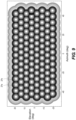
- the primary reflector dish 43 is substantially rectangular in plan view, viewed from a direction parallel to the direction of a radiofrequency main beam which the offset Gregorian antenna arrangement is configured to form.
- the primary reflector dish 43 may be formed of pressed metal. This arrangement has been found to provide a compact design with high radiofrequency gain.
- the secondary reflector which is covered by the enclosure 49 , may also have a substantially rectangular in plan view, viewed from a direction parallel to the direction of a radiofrequency main beam which the offset Gregorian antenna arrangement is configured to form.
- the pre-determined plurality of antenna weight vectors are configured to form a plurality of beams from the primary reflector dish 43 as shown in FIG. 20 .
- FIG. 20 shows that the position of each of the plurality of beams is overlaid, in a similar arrangement to that of FIG. 8 .
- a reduced set of beams is used for communication, shown within an ellipse 35 . At least some of the rows are truncated at each end. The resulting truncated rows are longest towards the centre of the range of elevation values.
- the orientations of the beams are arranged in a grid comprising a plurality of rows 34 , the beams of each row being spaced in angular position in the row by a first angular separation 29 on a first axis 32 , in this example azimuth.
- the angular positions of the beams of each row is offset 30 on the first axis 32 by half of the first angular separation 29 with respect to the angular positions of beams in an adjacent row.
- each beam in row 34 is offset by half the separation between beams 29 with respect to the angular positions of beams in an adjacent row.
- the beam numbers, selected from a 1-120 range, shown in FIG. 20 relate to an optional the special case of an order of addressing each beam in a search process, in which every fourth numerical beam is selected to form the first sub-set of beams.
- the second subset of beams may be selected by selecting the preceding 10 and following 10 beams in numerical order of the numbering system. This selects a second subset of beams which at least includes the six beams surrounding a selected beam. This provides a simple algorithm for selecting beams.
- each row is separated from an adjacent row by the first angular separation 29 multiplied by cosine 30 degrees on a second axis, perpendicular to the first axis 32 , so that each beam of the plurality of beams is arranged as an equilateral triangle with two adjacent beams.
- the positions of the beams will be subject to errors due to the accuracy of the beamforming weights, taking into account the effects of quantisation.
- a first sub-set of the pre-determined plurality of antenna weight vectors is selected, as shown as circled beams 28 .
- 26 beams are selected for the sub-set.
- FIG. 21 shows a plot of antenna gain for the beam arrangement of FIG. 17 , showing the maximum gain that can be achieved at each point in the arrangement by selection of the best beam, similarly to FIG. 9 .
- the contours are in steps of 1 dB.
- a succession of beams is formed in a first time sequence at the first station using the first sub-set of the pre-determined plurality of antenna weight vectors to send first messages.
- the first beam is used as the basis of a finer refinement process.
- the acknowledgement from the second station may be carried in the first beam in the case that the first beam is used for both transmit and receive in a time division duplex arrangement.
- a refined search is carried out using a further succession of beams formed at the first station using a second sub-set of the pre-determined plurality of antenna weight vectors selected to form beams adjacent to the first beam. As shown in FIG.
- the second sub-set is selected to form at least a ring of six beams surrounding the respective first and second beams if the first or second beam is not at an edge of the grid.
- the second sub-set of beams is shown in FIG. 17 by the beams marked by squares, 39 a , 39 b , etc., which surround the first beam 38 which was selected in the initial acquisition process. This provides an efficient process for selecting a best beam for use after establishing initial communication.
- FIG. 22 shows the arrangement of the feed beams generated by the array of antenna elements to feed the secondary reflector, and to produce the arrangement of beams from the primary reflector dish shown in FIG. 20 and FIG. 21 .
- Each feed beam number in FIG. 22 produces the correspondingly numbered beam from the primary reflector dish as shown in FIG. 20 .
- the relationship between the azimuth and elevation direction of each feed beam and the azimuth and elevation direction of the respective beam from the primary reflector dish is a non-linear function of azimuth and elevation.
- the pre-determined plurality of antenna weight vectors is configured to form the plurality of feed beams such that the orientations of the plurality of beams is arranged in a distorted grid comprising a plurality of curved rows 36 a , 36 b , etc., each curved row providing a monotonic change in azimuth 32 angle along the curved row, and a non-monotonic change in elevation 33 angle along the curved row.
- each curved row 36 a , 36 b , etc. has an offset in elevation angle between the centre of the curved row and either end of the curved row.
- the offset in elevation angle for a curved row is equal to the angular spacing in elevation between the curved row and an adjacent curved row +/ ⁇ 50%.
- each curved row has a greater elevation angle at the centre of the curved row than at either end of the curved row, and in this example each curved row has an approximately parabolic dependence of elevation angle on azimuth angle, within +/ ⁇ 50% of a true parabola.
- x 1 x 2 ((0.12 ⁇ 0.0052 y ) y +0.17)+0.21 x 3 +x ((0.16 y+ 0.55) y ⁇ 13.)+ y (( ⁇ 0.27 y ⁇ 0.55) y ⁇ 0.27) ⁇ 0.38
- y 1 x 2 ((0.061 ⁇ 0.047 y ) y ⁇ 1.7)+0.077 x 3 +x ((0.030 y +0.00061) y ⁇ 0.46)+ y ((0.45 y ⁇ 0.48) y ⁇ 14.) ⁇ 5.8
- Both the first and second wireless station may form a plurality of beams during the process of establishing communication.
- the second station has an antenna comprising an array of antenna elements and a beamforming network, the beamforming network being configured to form a beam using an antenna weight vector selected from a pre-determined plurality of antenna weight vectors.
- the method comprises providing a second pre-determined plurality of antenna weight vectors at the second station configured to form a second plurality of beams, the orientations of the second plurality of beams being arranged in a second grid comprising a plurality of rows, the beams of each row being spaced in angular position in the row by a second angular separation, the angular position of the beams of each row being offset by half of the second angular separation with respect to the angular positions of beams in an adjacent row.
- a sub-set of the second pre-determined plurality of antenna weight vectors are selected for use at the second station.
- a succession of beams are formed in a second time sequence at the second station using the sub-set of the second pre-determined plurality of antenna weight vectors.
- FIG. 23 is a flow diagram of a method in an example, according to steps S 23 . 1 , S 23 . 2 , S 23 . 3 and S 23 . 4 .
- the wireless communication system may have an operating frequency of is a least 50 GHz. In other examples, the wireless communication system may have an operating frequency of greater than 28 GHz, for example 28 GHz.
Landscapes
- Engineering & Computer Science (AREA)
- Computer Networks & Wireless Communication (AREA)
- Signal Processing (AREA)
- Aerials With Secondary Devices (AREA)
Abstract
Description
-
- an offset Gregorian antenna arrangement comprising a primary reflector dish and a secondary reflector;
- an array of antenna elements arranged as a feed for the secondary reflector, the array of antenna elements and the secondary reflector being offset in a vertical axis with respect to a centre of the primary reflector dish;
- a beamforming network, the beamforming network being configured to form a beam using an antenna weight vector; and
- a processor configured to provide an antenna weight vector selected from a pre-determined plurality of antenna weight vectors to the beamformer,
- wherein the processor is configured to provide the pre-determined plurality of antenna weight vectors configured to form a plurality of beams, the orientations of the plurality of beams being arranged in a grid comprising a plurality of rows, each of the pre-determined plurality of antenna weight vectors being configured to form a respective beam from the primary reflector dish of the Gregorian antenna arrangement by forming a respective feed beam from the array of antenna elements,
- wherein the relationship between the azimuth and elevation direction of each feed beam and the azimuth and elevation direction of the respective beam from the primary reflector dish is a non-linear function of azimuth and elevation.
-
- providing the pre-determined plurality of antenna weight vectors configured to form a plurality of beams, the orientations of the plurality of beams being arranged in a grid comprising a plurality of rows, each of the pre-determined plurality of antenna weight vectors being configured to form a respective beam from the primary reflector dish of the Gregorian antenna arrangement by forming a respective feed beam from the array of antenna elements,
- wherein the array of antenna elements and the secondary reflector are offset in a vertical axis with respect to a centre of the primary reflector dish, and the relationship between the azimuth and elevation direction of each feed beam and the azimuth and elevation direction of the respective beam from the primary reflector dish is a non-linear function of azimuth and elevation.
x1=x 2((0.12−0.0052y)y+0.17)+0.21x 3 +x((0.16y+0.55)y−13.)+y((−0.27y−0.55)y−0.27)−0.38
y1=x 2((0.061−0.047y)y−1.7)+0.077x 3 +x((0.030y+0.00061)y−0.46)+y((0.45y−0.48)y−14.)−5.8
Claims (16)
Priority Applications (1)
| Application Number | Priority Date | Filing Date | Title |
|---|---|---|---|
| US18/310,313 US12267142B2 (en) | 2020-12-11 | 2023-05-01 | Forming a beam from a subscriber module of a fixed wireless access communication system |
Applications Claiming Priority (5)
| Application Number | Priority Date | Filing Date | Title |
|---|---|---|---|
| GB2019618.4A GB2601816B (en) | 2020-12-11 | 2020-12-11 | Forming a beam from a subscriber module of a fixed wireless access communication system |
| GB2019618 | 2020-12-11 | ||
| GB2019618.4 | 2020-12-11 | ||
| US17/547,022 US11677456B2 (en) | 2020-12-11 | 2021-12-09 | Forming a beam from a subscriber module of a fixed wireless access communication system |
| US18/310,313 US12267142B2 (en) | 2020-12-11 | 2023-05-01 | Forming a beam from a subscriber module of a fixed wireless access communication system |
Related Parent Applications (1)
| Application Number | Title | Priority Date | Filing Date |
|---|---|---|---|
| US17/547,022 Continuation US11677456B2 (en) | 2020-12-11 | 2021-12-09 | Forming a beam from a subscriber module of a fixed wireless access communication system |
Publications (2)
| Publication Number | Publication Date |
|---|---|
| US20230268978A1 US20230268978A1 (en) | 2023-08-24 |
| US12267142B2 true US12267142B2 (en) | 2025-04-01 |
Family
ID=79230638
Family Applications (1)
| Application Number | Title | Priority Date | Filing Date |
|---|---|---|---|
| US18/310,313 Active US12267142B2 (en) | 2020-12-11 | 2023-05-01 | Forming a beam from a subscriber module of a fixed wireless access communication system |
Country Status (3)
| Country | Link |
|---|---|
| US (1) | US12267142B2 (en) |
| EP (1) | EP4260483A1 (en) |
| WO (1) | WO2022123052A1 (en) |
Citations (12)
| Publication number | Priority date | Publication date | Assignee | Title |
|---|---|---|---|---|
| EP1020952A1 (en) | 1999-01-15 | 2000-07-19 | TRW Inc. | Gregorian antenna system |
| US6204822B1 (en) | 1998-05-20 | 2001-03-20 | L-3 Communications/Essco, Inc. | Multibeam satellite communication antenna |
| US8335167B1 (en) | 2009-02-02 | 2012-12-18 | Marvell International Ltd. | Refining beamforming techniques for phased-array antennas |
| US20160037431A1 (en) | 2013-03-15 | 2016-02-04 | Facebook, Inc. | Millimeter wave non-line-of-sight |
| US20160372835A1 (en) | 2014-03-05 | 2016-12-22 | Agence Spatiale Europeenne | Imaging antenna systems with compensated optical aberrations based on unshaped surface reflectors |
| US20170134076A1 (en) | 2015-11-06 | 2017-05-11 | Futurewei Technologies, Inc. | Method and Apparatus for Multiuser MIMO Beamforming Training |
| US20180331740A1 (en) | 2017-05-11 | 2018-11-15 | Intel Corporation | Multi-finger beamforming and array pattern synthesis |
| US10530434B2 (en) | 2016-01-07 | 2020-01-07 | Sony Corporation | Wireless communication method and wireless communication device |
| US20200119790A1 (en) | 2018-10-15 | 2020-04-16 | Blue Danube Systems, Inc. | Enhancing throughput using agile beam switching and user scheduling in cellular systems |
| US20200295469A1 (en) | 2019-03-15 | 2020-09-17 | Massachusetts Institute Of Technology | Inflatable reflector antenna and related methods |
| US10812125B1 (en) | 2019-05-31 | 2020-10-20 | Intel Corporation | Radiation exposure control for beamforming technologies |
| US11621754B2 (en) * | 2020-10-09 | 2023-04-04 | Huawei Technologies Co., Ltd. | Analog beamforming method for mitigating beam squint effect in wideband phased array antennas |
-
2021
- 2021-12-10 WO PCT/EP2021/085289 patent/WO2022123052A1/en not_active Ceased
- 2021-12-10 EP EP21836125.1A patent/EP4260483A1/en active Pending
-
2023
- 2023-05-01 US US18/310,313 patent/US12267142B2/en active Active
Patent Citations (12)
| Publication number | Priority date | Publication date | Assignee | Title |
|---|---|---|---|---|
| US6204822B1 (en) | 1998-05-20 | 2001-03-20 | L-3 Communications/Essco, Inc. | Multibeam satellite communication antenna |
| EP1020952A1 (en) | 1999-01-15 | 2000-07-19 | TRW Inc. | Gregorian antenna system |
| US8335167B1 (en) | 2009-02-02 | 2012-12-18 | Marvell International Ltd. | Refining beamforming techniques for phased-array antennas |
| US20160037431A1 (en) | 2013-03-15 | 2016-02-04 | Facebook, Inc. | Millimeter wave non-line-of-sight |
| US20160372835A1 (en) | 2014-03-05 | 2016-12-22 | Agence Spatiale Europeenne | Imaging antenna systems with compensated optical aberrations based on unshaped surface reflectors |
| US20170134076A1 (en) | 2015-11-06 | 2017-05-11 | Futurewei Technologies, Inc. | Method and Apparatus for Multiuser MIMO Beamforming Training |
| US10530434B2 (en) | 2016-01-07 | 2020-01-07 | Sony Corporation | Wireless communication method and wireless communication device |
| US20180331740A1 (en) | 2017-05-11 | 2018-11-15 | Intel Corporation | Multi-finger beamforming and array pattern synthesis |
| US20200119790A1 (en) | 2018-10-15 | 2020-04-16 | Blue Danube Systems, Inc. | Enhancing throughput using agile beam switching and user scheduling in cellular systems |
| US20200295469A1 (en) | 2019-03-15 | 2020-09-17 | Massachusetts Institute Of Technology | Inflatable reflector antenna and related methods |
| US10812125B1 (en) | 2019-05-31 | 2020-10-20 | Intel Corporation | Radiation exposure control for beamforming technologies |
| US11621754B2 (en) * | 2020-10-09 | 2023-04-04 | Huawei Technologies Co., Ltd. | Analog beamforming method for mitigating beam squint effect in wideband phased array antennas |
Non-Patent Citations (4)
| Title |
|---|
| International Search Report and Written Opinion of the International Search Authority mailed Apr. 19, 2022, in International Application No. PCT/EP2022/085289 (16 pp.). |
| Martinez-Lorenzo et al., "Zooming and Scanning Gregorian Confocal Dual Reflector Antennas," Sep. 2008 (10 pages). |
| Q. Lai et al, A digital beam-forming multiple-beam reflector antenna subsystem for GEO communication satellites 2016 46th European Microwave Conference (EuMC) 2016 pp. 866-869 dated Oct. 4, 2016 (4 pages). |
| Wei et al., "Multibeam Antenna Technologies for 5G Wireless Communications", IEEE Transactions on Antennas and Propagation, IEEE, USA, vol. 65, No. 12, Nov. 30, 2017, pp. 6231-6249, XP011673554, ISSN: 0018-926X, DOI: 10.1109/TAP.2017.2712819 [retrieved on Nov. 28, 2017] (19 pp.). |
Also Published As
| Publication number | Publication date |
|---|---|
| WO2022123052A1 (en) | 2022-06-16 |
| US20230268978A1 (en) | 2023-08-24 |
| EP4260483A1 (en) | 2023-10-18 |
Similar Documents
| Publication | Publication Date | Title |
|---|---|---|
| US12199715B2 (en) | Small cell beam-forming antennas | |
| US5973641A (en) | Antenna feed network arrangement | |
| US10566698B2 (en) | Multifocal phased array fed reflector antenna | |
| US11197173B2 (en) | Multi-band cellular antenna system | |
| US11962072B2 (en) | Phased array antennas having switched elevation beamwidths and related methods | |
| CN109586043A (en) | For reducing the antenna for base station with lens of upwardly-directed radiation | |
| US10418723B1 (en) | Dual polarized circular or cylindrical antenna array | |
| US11411301B2 (en) | Compact multiband feed for small cell base station antennas | |
| US20060125706A1 (en) | High performance multimode horn for communications and tracking | |
| US12143175B2 (en) | Establishing wireless communication in a system forming a beam by selecting from a pre-determined plurality of antenna weight vectors | |
| US11677456B2 (en) | Forming a beam from a subscriber module of a fixed wireless access communication system | |
| US11711117B2 (en) | Establishing wireless communication in a system forming a beam by selecting from a pre-determined plurality of antenna weight vectors | |
| US12267142B2 (en) | Forming a beam from a subscriber module of a fixed wireless access communication system | |
| GB2367188A (en) | Shaped antenna beam | |
| EP3840118A1 (en) | Multibeam antenna | |
| JP3822607B2 (en) | Array antenna | |
| Manoochehri et al. | A new method for designing high efficiency multi feed multi beam reflector antennas | |
| US3587108A (en) | Transmitting antenna employing end-fire elements | |
| CN116686231A (en) | Establishing wireless communication in a beam forming system by selecting from a predetermined plurality of antenna weight vectors | |
| RU8165U1 (en) | ANTENNA ARRAY WITH REJECTED BEAM OF THE DIRECTION DIAGRAM | |
| Hoffman et al. | Directional Zig-Zag Antenna at KERO-TV, Bakersfield, California | |
| Ohkubo et al. | Optimization in the design of a 12 gigahertz low cost ground receiving system for broadcast satellites. Volume 2: Antenna system and interference |
Legal Events
| Date | Code | Title | Description |
|---|---|---|---|
| FEPP | Fee payment procedure |
Free format text: ENTITY STATUS SET TO UNDISCOUNTED (ORIGINAL EVENT CODE: BIG.); ENTITY STATUS OF PATENT OWNER: LARGE ENTITY |
|
| STPP | Information on status: patent application and granting procedure in general |
Free format text: DOCKETED NEW CASE - READY FOR EXAMINATION |
|
| AS | Assignment |
Owner name: CAMBIUM NETWORKS LTD., UNITED KINGDOM Free format text: ASSIGNMENT OF ASSIGNORS INTEREST;ASSIGNORS:KING, NIGEL JONATHAN RICHARD;MUTHIAH, THIRUMARAN;FULLER, MATT;SIGNING DATES FROM 20230119 TO 20230223;REEL/FRAME:064577/0066 |
|
| STPP | Information on status: patent application and granting procedure in general |
Free format text: NON FINAL ACTION MAILED |
|
| STPP | Information on status: patent application and granting procedure in general |
Free format text: RESPONSE TO NON-FINAL OFFICE ACTION ENTERED AND FORWARDED TO EXAMINER |
|
| STPP | Information on status: patent application and granting procedure in general |
Free format text: FINAL REJECTION MAILED |
|
| STPP | Information on status: patent application and granting procedure in general |
Free format text: RESPONSE AFTER FINAL ACTION FORWARDED TO EXAMINER |
|
| STPP | Information on status: patent application and granting procedure in general |
Free format text: NOTICE OF ALLOWANCE MAILED -- APPLICATION RECEIVED IN OFFICE OF PUBLICATIONS |
|
| STPP | Information on status: patent application and granting procedure in general |
Free format text: DOCKETED NEW CASE - READY FOR EXAMINATION |
|
| STPP | Information on status: patent application and granting procedure in general |
Free format text: NOTICE OF ALLOWANCE MAILED -- APPLICATION RECEIVED IN OFFICE OF PUBLICATIONS |
|
| STPP | Information on status: patent application and granting procedure in general |
Free format text: PUBLICATIONS -- ISSUE FEE PAYMENT VERIFIED |
|
| STCF | Information on status: patent grant |
Free format text: PATENTED CASE |