US12266258B2 - Video doorbell with chime controller - Google Patents
Video doorbell with chime controller Download PDFInfo
- Publication number
- US12266258B2 US12266258B2 US17/900,211 US202217900211A US12266258B2 US 12266258 B2 US12266258 B2 US 12266258B2 US 202217900211 A US202217900211 A US 202217900211A US 12266258 B2 US12266258 B2 US 12266258B2
- Authority
- US
- United States
- Prior art keywords
- chime
- doorbell
- video
- video doorbell
- controller
- Prior art date
- Legal status (The legal status is an assumption and is not a legal conclusion. Google has not performed a legal analysis and makes no representation as to the accuracy of the status listed.)
- Active, expires
Links
Images


Classifications
-
- H—ELECTRICITY
- H04—ELECTRIC COMMUNICATION TECHNIQUE
- H04N—PICTORIAL COMMUNICATION, e.g. TELEVISION
- H04N7/00—Television systems
- H04N7/18—Closed-circuit television [CCTV] systems, i.e. systems in which the video signal is not broadcast
- H04N7/183—Closed-circuit television [CCTV] systems, i.e. systems in which the video signal is not broadcast for receiving images from a single remote source
- H04N7/186—Video door telephones
-
- G—PHYSICS
- G08—SIGNALLING
- G08B—SIGNALLING SYSTEMS, e.g. PERSONAL CALLING SYSTEMS; ORDER TELEGRAPHS; ALARM SYSTEMS
- G08B13/00—Burglar, theft or intruder alarms
- G08B13/18—Actuation by interference with heat, light, or radiation of shorter wavelength; Actuation by intruding sources of heat, light, or radiation of shorter wavelength
- G08B13/189—Actuation by interference with heat, light, or radiation of shorter wavelength; Actuation by intruding sources of heat, light, or radiation of shorter wavelength using passive radiation detection systems
- G08B13/194—Actuation by interference with heat, light, or radiation of shorter wavelength; Actuation by intruding sources of heat, light, or radiation of shorter wavelength using passive radiation detection systems using image scanning and comparing systems
- G08B13/196—Actuation by interference with heat, light, or radiation of shorter wavelength; Actuation by intruding sources of heat, light, or radiation of shorter wavelength using passive radiation detection systems using image scanning and comparing systems using television cameras
- G08B13/19634—Electrical details of the system, e.g. component blocks for carrying out specific functions
-
- G—PHYSICS
- G08—SIGNALLING
- G08B—SIGNALLING SYSTEMS, e.g. PERSONAL CALLING SYSTEMS; ORDER TELEGRAPHS; ALARM SYSTEMS
- G08B3/00—Audible signalling systems, e.g. audible personal calling systems
- G08B3/10—Audible signalling systems, e.g. audible personal calling systems using electric transmission; using electromagnetic transmission
Definitions
- the present invention relates to doorbell systems. More specifically, the present invention relates to a video doorbell system having a video doorbell and a chime controller, powered over two wires. The two wires provide full power to the video doorbell and a return-signaling method to activate the indoor chime.
- a video doorbell system operable to generate a chime sound, comprising a transformer, operable to convert a premise's power supply to a suitable voltage for the video doorbell system.
- the video doorbell system further includes a video doorbell, the video doorbell having at least a processor, a video camera operable to record video, and a wireless communication module operable to transmit video from the video camera across a remote network, the video doorbell being electrically connected to the transformer by a two-wire interface, the video doorbell further having a doorbell button, the processor within the video doorbell operable to generate a chime signal using power supplied from the two-wire interface when the doorbell button is depressed.
- the video doorbell system further includes a chime controller, electrically connected to the transformer and the video doorbell by the two-wire interface, the chime controller operable to receive the chime signal across at least one wire of the two-wire interface and activate a chime generator to generate a chime sound.
- the video doorbell system continues to provide sufficient power to the video doorbell from the transformer via the two-wire interface so as to be able to operate the processor, video camera and wireless communication module while the doorbell button is currently depressed.
- FIG. 1 shows a block diagram of a prior art doorbell system
- FIG. 2 shows a schematic representation of a premise containing a video doorbell system in accordance with an embodiment of the invention
- FIG. 3 A shows an electrical block diagram of the video doorbell system shown in FIG. 2 ;
- FIG. 3 B and 3 C show schematic representation of the components of the video doorbell shown in FIG. 3 A ;
- FIG. 4 A shows a simulation chart of voltage over time between the video doorbell and a chime controller for the video doorbell system shown in FIG. 3 ;
- FIG. 5 shows an electrical block diagram of the video doorbell system shown in FIG. 3 ;
- FIG. 6 shows a simulation of chart of voltage delays over time used within the video doorbell system shown in FIG. 3 ;
- FIG. 7 shows an electrical block diagram of signalling current within the video doorbell system shown in FIG. 3 ;
- FIG. 8 shows a simulation chart of current imbalance over time in the signalling current within the electrical block diagram shown in FIG. 7 ;
- FIG. 9 A shows an electrical block diagram of an incorrectly-wired video doorbell system shown in FIG. 3 ;
- FIG. 9 B shows an electrical block diagram of a correctly-wired video doorbell system shown in FIG. 3 ;
- FIG. 10 shows an electrical block diagram of another embodiment of the video doorbell system shown in FIG. 3 .
- a typical prior art doorbell system (as shown in FIG. 1 ) generally at 10 is a simple system, consisting of three major components: a transformer 12 , an indoor chime 14 and a doorbell 16 having a doorbell button 18 (typically located outside the premise).
- Transformer 12 transforms a premise's 120 VAC to 16-24 AC.
- a two-wire interface (16-24 VAC) go from the transformer 12 to the indoor chime 14 (typically located within the premise) and two wires go from the indoor chime 14 to the (outdoor) doorbell 16 to create the circuit as shown.
- doorbell button 18 on doorbell 16 is depressed the circuit completes and the indoor chime 14 is powered for the duration the doorbell button 18 is being pressed in order to create a chime noise.
- doorbell button 18 is released, the circuit disconnects power to the indoor chime 14 .
- prior art doorbell systems 10 using two-wire interfaces overcome this power disruption by having an internal rechargeable battery 20 located within doorbell 16 to provide constant power to the video doorbell circuitry for the duration that doorbell button 18 is pressed.
- an internal rechargeable battery 20 located within doorbell 16 to provide constant power to the video doorbell circuitry for the duration that doorbell button 18 is pressed.
- doorbell button 18 is not pressed, a small amount of the power from the two-wire interface is used to recharge battery 20 , ready to provide backup power on the next press of doorbell button 18 .
- the rechargeable battery 20 does not perform well in extreme cold temperatures.
- the capacity of the rechargeable battery 20 reduces over time, reducing the overall lifespan of doorbell 16 . Elevated temperatures within the housing of doorbell 16 can further reduce the longevity of the rechargeable battery 20 .
- Rechargeable battery 20 adds bulk and cost to the product.
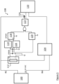
- Premise 22 is typically a residential home, but in some embodiments, could also be a commercial building. Premise 22 is defined by and subdivided into multiple rooms (functionally, the kitchen, bedroom, hallway, etc.) by a plurality of walls 24 . Some walls 24 are interior walls 24 A (including both load-bearing and non-load bearing walls) and some are exterior walls 24 B (thicker load-bearing walls, preferably well insulated). For simplicity, other features of premise 22 such as doors, windows, stairs, etc. have been omitted from FIG. 2 .
- Premise 22 includes a plurality of smart devices, which can be considered either “hub” devices or “remote” devices. While not a strict delineation, hub devices are powered by the premise's 120 VAC electrical wiring (not depicted) and thus can have robust communication and computational abilities such as Wi-Fi and video streaming, whereas remote devices have constrained power, communication and computational abilities. As will be described in greater detail below, remote devices communicate with each other and/or hub devices locally within premise 22 , whereas hub devices are also operable to communicate with remote servers outside of premise 22 via a network 38 . In the present embodiment, hub devices include a smart thermostat 26 , smart camera 28 and a video doorbell system 30 . Remote devices in the present embodiment include remote sensors 32 and contact sensors 34 . Other remote devices such as sirens and leak sensors (neither depicted) are also contemplated. Collectively, the hub and remote devices support a plurality of home automation applications.
- Premise 22 further includes a HVAC system 36 , which may include various heating and cooling systems furnaces, air conditioning systems, fans, heat pumps, humidification/dehumidification systems and the like. HVAC system 36 is preferably controlled by smart thermostat 26 .
- Network 38 can include a local area networks (LAN) as well as connectivity to the Internet via a router (not depicted) or communication over a cellular network.
- Network 38 can also include mesh networks that facilitate communication between hub and remote user devices 40 .
- the remote user devices 40 may communicate with the hub devices (such as smart thermostat 26 or video doorbell system 30 ) directly on same network 38 or indirectly via a remote server 42 across the Internet.
- Remote user devices 40 can include smart phones, smart watches, tablets as well as personal computers. These remote user devices 40 can control hub devices such as smart thermostat 26 or view video content from smart camera 28 or video doorbell system 30 .
- smart thermostat 26 is operable to act as a hub device.
- smart thermostat 26 is a wireless communicating thermostat, such as the ecobee3lite or ecobee Smart Thermostat with Voice.
- smart thermostat 26 is equipped with wireless communication protocols such as Wi-Fi or Bluetooth to connect to the network 38 to provide for remote control of smart thermostat 26 from the remote user device 40 .
- the remote user devices 40 may communicating with smart thermostat 26 directly on same network 38 or indirectly via the remote server 42 across the Internet.
- Smart thermostat 26 is further in wireless communication with a one or more remote sensor(s) 32 , which can provide different sensor readings such as occupancy, temperature, humidity, as well as CO or CO2 values to smart thermostat 26 (via wireless protocols such as 802.11, Bluetooth, Zigbee HA or through a proprietary 900 MHz protocol). Smart thermostat 26 is operable to communicate with remote sensor(s) 32 to provide occupancy and temperature averaging for its readings, and then prioritize temperature values in rooms 12 where occupancy is detected, and/or reduce the usage of HVAC system 36 when no occupancy is detected within premise 22 for an extended period of time. Smart thermostat 26 may also include its own occupancy sensor. Preferably, smart thermostat 26 also includes a touchscreen, a microphone and speaker. In some embodiments, the touchscreen and speakers on smart thermostat 26 can act as an output for video streams provided by smart camera 28 or video doorbell system 30 , or for door chime signals generated by video doorbell system 30 .
- Video doorbell system 30 ( FIG. 3 A ) includes a transformer 100 (located within premise 22 ), a chime 102 (located within premise 22 ) and a video doorbell 104 which is adapted to be installed on the outside of premise 22 on an external wall.
- Transformer 100 , chime 102 and video doorbell 104 are all connected by a standard two-wire interface.
- External hardware components of video doorbell 104 include a weather-proof housing 60 , a doorbell button 70 , a video camera 62 and IR lighting 64 (typically all forward facing).
- Doorbell button 70 is typically a plunger-style actuator operable to generate a door press signal in processor 80 (described below).
- Video doorbell 104 may also include one or more microphone apertures 66 which allow sounds from outside housing 60 to reach one or more internal microphones (described below) and a speaker grate 68 which allows sounds emitted from an internal speaker (discussed below) to exit housing 60 .
- Video doorbell 104 Internal components of video doorbell 104 ( FIG. 3 C ) include includes the processor 80 , which can be a microprocessor, or any other suitable device as will occur to those of skill in the art.
- Video doorbell 104 further includes memory 82 , which can be non-volatile RAM and/or volatile RAM which is accessible by processor 80 .
- memory 82 can be integral with processor 80 , or can be separate discrete devices or components, as desired.
- memory 82 will store one or more programs for execution by processor 80 (such as a camera detection program and local video storage).
- Video doorbell 104 may also include at least one environmental sensor 84 , which at a minimum is a temperature sensor operable to determine the current outdoor temperature, but can also include other environmental sensors, such as a humidity sensor.
- a communication module 86 connected to processor 80 to allow processor 80 to communicate with network 38 (i.e., the Internet) and/or with additional external sensors or computerized devices (not shown).
- communication module 86 is operable to connect to the desired data networks wirelessly, via an antenna 88 , using at least one wireless communication protocol, such as Wi-Fi; Bluetooth; ZigBee; ZWave; Cellular Data, etc.
- Communication module 86 also allows video doorbell 104 to communicate with Internet based services running on remote servers 42 and with applications used remotely on remote user devices 40 . For example, a user remote from video doorbell 104 may access an application executing on a smartphone (remote user device 40 ) or personal computer to watch live streaming from video camera 62 .
- Video doorbell 104 further includes a control block 94 , which is adapted to connect to a standard two-wire interface found within premise 22 .
- Control block 94 provides the power supply and generates control signals across the two-wire interface within video doorbell system 30 , and is described in greater detail below.
- the hardware in video doorbell 104 further includes an audio output subsystem 96 , which is operable in response to signals received from processor 80 , to output an amplified audio signal to a speaker 98 (which is arranged to output sound through speaker grate 68 ).
- Audio output subsystem 96 can be a discrete device, or combination of suitable discrete devices, as desired and is preferably capable of outputting voice signals and/or simulated door chime sounds.
- Transformer 100 is adapted to transform premise 22 's 120 VAC power supply (not depicted) into 16-24 VAC.
- Transformer 100 is connected to chime 102 by a standard two-wire interface.
- Chime 102 includes a chassis 106 (located within premise 22 ). Inside chassis 106 is a chime controller 108 and a chime generator—in the present embodiment a chime solenoid 110 .
- Chime controller 108 is connected to video doorbell 104 via the standard two-wire interface.
- Transformer 100 feeds power to chime controller 108 and to chime solenoid 110 when the doorbell button 70 on the video doorbell 104 is pressed.
- Chime controller 108 provides connectivity to the chime solenoid 110 .
- the chime solenoid 110 When signaling from video doorbell 104 (described in greater detail below) is present (i.e., the doorbell button 70 is pressed), the chime solenoid 110 is energized for one or two seconds, causing an armature to strike a sound plate (neither depicted) to create the chime sound.
- Chime controller 108 further provides connectivity to video doorbell 104 .
- power is continuously provided to video doorbell 104 , regardless of whether the doorbell button 70 is pressed or not.
- video doorbell 104 provides special signaling to chime controller 108 when the doorbell button 70 is pressed.
- the special signalling is decoded by chime controller 108 , which causes chime solenoid 110 to be briefly powered to create the chime sound (described above).
- FIG. 4 A shows a simulation of what happens on the two-wire interface between the video doorbell 104 and chime controller 108 when the doorbell button 70 is pressed and there is a call for a chime (the waveform has been simplified for the purposes of illustration). The voltage is slightly reduced, but only on the negative sinusoid. The positive sinusoid remains intact.
- Video doorbell 104 sees this voltage as acceptable for its operation, although reduced overall amplitude, and still carries AC voltage and current over the two-wire interface.
- FIG. 4 B shows what the current consumption looks like on the two-wire interface during the signalling of a doorbell button 70 press which is a call for chime (waveform has been simplified for the purposes of illustration). The majority of negative current is being sunk at the time there is a call for chime. When there is no chime signaling, the current shown is the normal operating current of the video doorbell 104 .
- Chime controller 108 detects this current envelope and activates the chime solenoid 110 .
- FIG. 5 provides a block diagram of chime controller 108 shows the electrical processing from transformer 100 to chime solenoid 110 .
- transformer 100 transforms the premise's 120 VAC to 16-24 VAC.
- Two wires exit from transformer 100 , RC and RH.
- RC passes through current to voltage detector (12V) 112 .
- RC passes through the current to voltage detection (12V) 112 and then onward to the video doorbell 104 .
- Current to voltage detector (12V) 112 consists of a full wave current rectifier and a filtered current to voltage convertor.
- the output of current to voltage detector (12V) 112 is a voltage level that is representative of the current consumption of the video doorbell 104 with respect to a virtual ground. As the current to the video doorbell 104 increase/decreases so does the Voltage (VRAW) output of the current to voltage detector (12V) 112 .
- VRAW Voltage
- the full wave current rectifier in current to voltage detector (12V) 112 passes current to the video doorbell 104 on the positive and negative current sinusoid.
- Half of the current sinusoid is fully passed to the video doorbell 104 .
- the other half of the current sinusoid is processed to generate a local voltage (VRAW) with a virtual ground and then passed to the video doorbell 104 .
- VRAW local voltage
- the voltage to the video doorbell 104 is slightly altered (as previously shown).
- the output of voltage detector (12V) 112 (VRAW) is filtered into a power domain called OPWR which feeds the rest of the detection circuit.
- VRAW and OPWR feed into time delay circuits, TD 114 and TD 116 respectively before going into a comparator 118 .
- the output of TD 114 goes into the minus of comparator 118 . It has the faster time constant compared to TD 116 (VNODE).
- the difference in time delays is shown in the timing diagram shown in FIG. 6 (voltage waveforms have been simplified for the purposes of illustration). As can be seen, when there is a rapid change in current consumption, TD 114 (VREF) quickly raises to a representative voltage level. Meanwhile TD 116 (VNODE) slowly catches up to TD 114 voltage level.
- TD 114 When TD 114 equals in voltage to TD 116 the hysteresis of comparator 118 kicks in to switch the output polarity.
- the time TD 114 voltage level remains above TD 116 voltage is the duration the chime solenoid 110 is activated. In the illustration shown in FIG. 6 , this is approximately 1.5 seconds. Elements of TD 114 and TD 116 may be adjusted to change the time the chime solenoid 110 is active (and thus, the length of the chime sound).
- the time delay circuits, TD 114 and TD 116 are comprised of resistor and capacitors components (not individually depicted). At start-up, there is no initial voltage on the capacitors. As power is applied to the chime controller 108 , the behavior of TD 114 and TD 116 is indeterminant and will cause the comparator 118 output to oscillate. This in effect will cause the chime solenoid 110 to erratically activate as power stabilizes to the system and initializes all capacitor reference voltages. To disable this start-up erratic behavior, a DWELL circuit 120 is provided that blocks an opto-triac circuit 122 from activation for a certain length of time while system voltages are stabilizing. Once the DWELL circuit 120 achieves the hold off time period, it allows comparator 188 to control opto-triac circuit 122 . In this way any inadvertent chime solenoid 110 activations are blocked as power is connected to the system.
- the opto-triac circuit 122 is an AC switch to turn on and off the chime solenoid 110 .
- Opto-triac circuit 122 is used to provide isolation to the OPWR subsystem while controlling the AC voltage.
- the opto-triac circuit 122 feeds into a power triac 124 to take care of the heavy current demands of the chime solenoid 110 .
- FIG. 7 provides a simplistic block diagram of the control block 94 in video doorbell 104 , showing how the signaling current (call for chime) is created from a press of the doorbell button 70 .
- a processor 80 monitors the doorbell button 70 press as shown on the left side of FIG. 7 . After a doorbell button 70 press detection, processor 80 debounces the doorbell button 70 signal and registers a valid doorbell button 70 press.
- a general input/output signal (GPIO) is then generated to activate an LED 130 in the opto-triac circuit 122 .
- the opto-triac circuit 122 allows half the current sinusoid with the help of a diode 132 to sink current through a resistor 134 .
- FIG. 8 provides a diagram for what is seen through simulation with the situation described above (waveform has been simplified for the purposes of illustration). Further to the block diagram shown in FIG. 7 , there is an option for the doorbell button 70 to directly control the opto-triac circuit 122 . This may happen if somehow processor 80 fails to boot, then video doorbell 104 should still be able to operate chime 102 .
- an inline detection circuit 136 located within must coincide with the same AC line that the video doorbell 104 uses to create the signaling current via a signalling current generator 140 .
- FIG. 9 A (incorrect installation) and FIG. 9 B (correct installation) illustrates the problem.
- the inline detection circuit 136 in chime controller 108 connects to both wires AC 1 and AC 2 .
- a doorbell button 70 press both signaling current generators 140 A and 140 B activate to generate the chime signal, and detection circuit 136 will detect either.
Landscapes
- Physics & Mathematics (AREA)
- Engineering & Computer Science (AREA)
- Multimedia (AREA)
- Signal Processing (AREA)
- Electromagnetism (AREA)
- General Physics & Mathematics (AREA)
- Interconnected Communication Systems, Intercoms, And Interphones (AREA)
Abstract
Description
Claims (5)
Priority Applications (2)
| Application Number | Priority Date | Filing Date | Title |
|---|---|---|---|
| US17/900,211 US12266258B2 (en) | 2021-08-31 | 2022-08-31 | Video doorbell with chime controller |
| US19/070,613 US20250201087A1 (en) | 2021-08-31 | 2025-03-05 | Video doorbell with chime controller |
Applications Claiming Priority (2)
| Application Number | Priority Date | Filing Date | Title |
|---|---|---|---|
| US202163239404P | 2021-08-31 | 2021-08-31 | |
| US17/900,211 US12266258B2 (en) | 2021-08-31 | 2022-08-31 | Video doorbell with chime controller |
Related Child Applications (1)
| Application Number | Title | Priority Date | Filing Date |
|---|---|---|---|
| US19/070,613 Continuation US20250201087A1 (en) | 2021-08-31 | 2025-03-05 | Video doorbell with chime controller |
Publications (2)
| Publication Number | Publication Date |
|---|---|
| US20230066779A1 US20230066779A1 (en) | 2023-03-02 |
| US12266258B2 true US12266258B2 (en) | 2025-04-01 |
Family
ID=85287357
Family Applications (2)
| Application Number | Title | Priority Date | Filing Date |
|---|---|---|---|
| US17/900,211 Active 2042-11-24 US12266258B2 (en) | 2021-08-31 | 2022-08-31 | Video doorbell with chime controller |
| US19/070,613 Pending US20250201087A1 (en) | 2021-08-31 | 2025-03-05 | Video doorbell with chime controller |
Family Applications After (1)
| Application Number | Title | Priority Date | Filing Date |
|---|---|---|---|
| US19/070,613 Pending US20250201087A1 (en) | 2021-08-31 | 2025-03-05 | Video doorbell with chime controller |
Country Status (1)
| Country | Link |
|---|---|
| US (2) | US12266258B2 (en) |
Families Citing this family (1)
| Publication number | Priority date | Publication date | Assignee | Title |
|---|---|---|---|---|
| US20250124771A1 (en) * | 2023-10-16 | 2025-04-17 | Generac Power Systems, Inc. | Video doorbell with chime controller |
Citations (3)
| Publication number | Priority date | Publication date | Assignee | Title |
|---|---|---|---|---|
| US9859741B1 (en) * | 2016-08-10 | 2018-01-02 | Vivint, Inc. | Active power management |
| US20190149775A1 (en) * | 2017-11-15 | 2019-05-16 | Google Llc | Doorbell camera with battery at chime |
| US20230230461A1 (en) * | 2022-01-19 | 2023-07-20 | Wyze Labs, Inc. | System and method for smart doorbell integration |
-
2022
- 2022-08-31 US US17/900,211 patent/US12266258B2/en active Active
-
2025
- 2025-03-05 US US19/070,613 patent/US20250201087A1/en active Pending
Patent Citations (3)
| Publication number | Priority date | Publication date | Assignee | Title |
|---|---|---|---|---|
| US9859741B1 (en) * | 2016-08-10 | 2018-01-02 | Vivint, Inc. | Active power management |
| US20190149775A1 (en) * | 2017-11-15 | 2019-05-16 | Google Llc | Doorbell camera with battery at chime |
| US20230230461A1 (en) * | 2022-01-19 | 2023-07-20 | Wyze Labs, Inc. | System and method for smart doorbell integration |
Also Published As
| Publication number | Publication date |
|---|---|
| US20250201087A1 (en) | 2025-06-19 |
| US20230066779A1 (en) | 2023-03-02 |
Similar Documents
| Publication | Publication Date | Title |
|---|---|---|
| US10869006B2 (en) | Doorbell camera with battery at chime | |
| US10319213B1 (en) | Thermal management in smart doorbells | |
| CN114067794B (en) | Audio-based load control system | |
| US20210239831A1 (en) | Systems and methods of ultrasonic sensing in smart devices | |
| US20160323977A1 (en) | Intelligent lighting control system and method | |
| US8502660B2 (en) | Occupancy sensing with selective emission | |
| CN105005291B (en) | A kind of intelligent home furnishing control method, control device and control system | |
| US20210072378A1 (en) | Systems and methods of ultrasonic sensing in smart devices | |
| US12256038B2 (en) | Smart electronic chime and mechanical chime dehum board | |
| CN108270222A (en) | Electronic system sharing power supply with doorbell and power supply method thereof | |
| US20250201087A1 (en) | Video doorbell with chime controller | |
| JP7373500B2 (en) | Sensor-based lighting system with integrated wireless signal repeater | |
| CN110767225A (en) | Voice interaction method, device and system | |
| US11102457B1 (en) | Audio/video recording and communication doorbell devices | |
| CN110632854A (en) | Voice control method and device, voice control node and system and storage medium | |
| EP3145211B1 (en) | Communication apparatus and wireless communication system including the same | |
| CN114815635A (en) | Computer readable storage medium, intelligent panel and voice interaction method thereof | |
| US20250124771A1 (en) | Video doorbell with chime controller | |
| CN115453892A (en) | Intelligent household system capable of removing fragmentation | |
| WO2016061733A1 (en) | Internet-based cloud visual doorbell system and operation method therefor | |
| KR102075002B1 (en) | Lighting control device | |
| CN115933871A (en) | Intelligent device control method, device, intelligent system and storage medium | |
| CN120126466A (en) | Offline voice interaction control method and device | |
| CN119511899A (en) | Control system and control method based on human presence detection | |
| TW202343390A (en) | Residential safety monitoring system |
Legal Events
| Date | Code | Title | Description |
|---|---|---|---|
| FEPP | Fee payment procedure |
Free format text: ENTITY STATUS SET TO UNDISCOUNTED (ORIGINAL EVENT CODE: BIG.); ENTITY STATUS OF PATENT OWNER: LARGE ENTITY |
|
| AS | Assignment |
Owner name: ECOBEE TECHNOLOGIES ULC, CANADA Free format text: ASSIGNMENT OF ASSIGNORS INTEREST;ASSIGNOR:METSELAAR, JOHN THEODORE;REEL/FRAME:061187/0691 Effective date: 20220920 |
|
| STPP | Information on status: patent application and granting procedure in general |
Free format text: DOCKETED NEW CASE - READY FOR EXAMINATION |
|
| AS | Assignment |
Owner name: GENERAC POWER SYSTEMS, INC., WISCONSIN Free format text: ASSIGNMENT OF ASSIGNORS INTEREST;ASSIGNOR:ECOBEE TECHNOLOGIES ULC;REEL/FRAME:061784/0897 Effective date: 20221107 |
|
| STPP | Information on status: patent application and granting procedure in general |
Free format text: NON FINAL ACTION MAILED |
|
| AS | Assignment |
Owner name: JPMORGAN CHASE BANK, N.A., AS ADMINISTRATIVE AGENT, NEW YORK Free format text: AFTER-ACQUIRED INTELLECTUAL PROPERTY SECURITY AGREEMENT (THIRD SUPPLEMENTAL FILING);ASSIGNOR:GENERAC POWER SYSTEMS, INC.;REEL/FRAME:068283/0215 Effective date: 20240703 |
|
| STPP | Information on status: patent application and granting procedure in general |
Free format text: RESPONSE TO NON-FINAL OFFICE ACTION ENTERED AND FORWARDED TO EXAMINER |
|
| STPP | Information on status: patent application and granting procedure in general |
Free format text: NOTICE OF ALLOWANCE MAILED -- APPLICATION RECEIVED IN OFFICE OF PUBLICATIONS |
|
| STPP | Information on status: patent application and granting procedure in general |
Free format text: PUBLICATIONS -- ISSUE FEE PAYMENT RECEIVED |
|
| STCF | Information on status: patent grant |
Free format text: PATENTED CASE |