US12262488B2 - Display device and fabrication method of display device - Google Patents
Display device and fabrication method of display device Download PDFInfo
- Publication number
- US12262488B2 US12262488B2 US17/964,484 US202217964484A US12262488B2 US 12262488 B2 US12262488 B2 US 12262488B2 US 202217964484 A US202217964484 A US 202217964484A US 12262488 B2 US12262488 B2 US 12262488B2
- Authority
- US
- United States
- Prior art keywords
- rolling member
- display panel
- support member
- rolling
- display device
- Prior art date
- Legal status (The legal status is an assumption and is not a legal conclusion. Google has not performed a legal analysis and makes no representation as to the accuracy of the status listed.)
- Active, expires
Links
Images


Classifications
-
- H—ELECTRICITY
- H05—ELECTRIC TECHNIQUES NOT OTHERWISE PROVIDED FOR
- H05K—PRINTED CIRCUITS; CASINGS OR CONSTRUCTIONAL DETAILS OF ELECTRIC APPARATUS; MANUFACTURE OF ASSEMBLAGES OF ELECTRICAL COMPONENTS
- H05K5/00—Casings, cabinets or drawers for electric apparatus
- H05K5/02—Details
- H05K5/0217—Mechanical details of casings
-
- G—PHYSICS
- G06—COMPUTING OR CALCULATING; COUNTING
- G06F—ELECTRIC DIGITAL DATA PROCESSING
- G06F1/00—Details not covered by groups G06F3/00 - G06F13/00 and G06F21/00
- G06F1/16—Constructional details or arrangements
- G06F1/1613—Constructional details or arrangements for portable computers
- G06F1/1633—Constructional details or arrangements of portable computers not specific to the type of enclosures covered by groups G06F1/1615 - G06F1/1626
- G06F1/1637—Details related to the display arrangement, including those related to the mounting of the display in the housing
- G06F1/1652—Details related to the display arrangement, including those related to the mounting of the display in the housing the display being flexible, e.g. mimicking a sheet of paper, or rollable
-
- G—PHYSICS
- G09—EDUCATION; CRYPTOGRAPHY; DISPLAY; ADVERTISING; SEALS
- G09F—DISPLAYING; ADVERTISING; SIGNS; LABELS OR NAME-PLATES; SEALS
- G09F9/00—Indicating arrangements for variable information in which the information is built-up on a support by selection or combination of individual elements
- G09F9/30—Indicating arrangements for variable information in which the information is built-up on a support by selection or combination of individual elements in which the desired character or characters are formed by combining individual elements
- G09F9/301—Indicating arrangements for variable information in which the information is built-up on a support by selection or combination of individual elements in which the desired character or characters are formed by combining individual elements flexible foldable or roll-able electronic displays, e.g. thin LCD, OLED
-
- H—ELECTRICITY
- H10—SEMICONDUCTOR DEVICES; ELECTRIC SOLID-STATE DEVICES NOT OTHERWISE PROVIDED FOR
- H10K—ORGANIC ELECTRIC SOLID-STATE DEVICES
- H10K50/00—Organic light-emitting devices
- H10K50/80—Constructional details
- H10K50/84—Passivation; Containers; Encapsulations
-
- H—ELECTRICITY
- H10—SEMICONDUCTOR DEVICES; ELECTRIC SOLID-STATE DEVICES NOT OTHERWISE PROVIDED FOR
- H10K—ORGANIC ELECTRIC SOLID-STATE DEVICES
- H10K59/00—Integrated devices, or assemblies of multiple devices, comprising at least one organic light-emitting element covered by group H10K50/00
-
- H—ELECTRICITY
- H10—SEMICONDUCTOR DEVICES; ELECTRIC SOLID-STATE DEVICES NOT OTHERWISE PROVIDED FOR
- H10K—ORGANIC ELECTRIC SOLID-STATE DEVICES
- H10K59/00—Integrated devices, or assemblies of multiple devices, comprising at least one organic light-emitting element covered by group H10K50/00
- H10K59/10—OLED displays
- H10K59/12—Active-matrix OLED [AMOLED] displays
- H10K59/131—Interconnections, e.g. wiring lines or terminals
-
- H—ELECTRICITY
- H10—SEMICONDUCTOR DEVICES; ELECTRIC SOLID-STATE DEVICES NOT OTHERWISE PROVIDED FOR
- H10K—ORGANIC ELECTRIC SOLID-STATE DEVICES
- H10K71/00—Manufacture or treatment specially adapted for the organic devices covered by this subclass
-
- H—ELECTRICITY
- H10—SEMICONDUCTOR DEVICES; ELECTRIC SOLID-STATE DEVICES NOT OTHERWISE PROVIDED FOR
- H10K—ORGANIC ELECTRIC SOLID-STATE DEVICES
- H10K77/00—Constructional details of devices covered by this subclass and not covered by groups H10K10/80, H10K30/80, H10K50/80 or H10K59/80
- H10K77/10—Substrates, e.g. flexible substrates
- H10K77/111—Flexible substrates
-
- H—ELECTRICITY
- H10—SEMICONDUCTOR DEVICES; ELECTRIC SOLID-STATE DEVICES NOT OTHERWISE PROVIDED FOR
- H10K—ORGANIC ELECTRIC SOLID-STATE DEVICES
- H10K2102/00—Constructional details relating to the organic devices covered by this subclass
- H10K2102/301—Details of OLEDs
- H10K2102/311—Flexible OLED
Definitions
- the disclosure generally relates to a display device and a fabrication method of a display device.
- a flexible display device may be implemented as a rollable display device in which a display panel can be rolled with a specific curvature radius.
- Embodiments provide a display device and a fabrication method thereof, which can minimize a defect of pixels included in a display panel by preventing damage which may occur in the display panel.
- a display device may include: a display panel that displays an image; and a roller connected to an end of the display panel.
- the roller may include a rolling member having a single body, the rolling member including a cut-off groove formed on at least a portion of an outer circumferential surface of the rolling member, and at least one support member disposed in an internal empty space of the rolling member.
- the at least one support member may include a first support member supporting a portion of an inner circumferential surface of the rolling member, and a second support member supporting another portion of the inner circumferential surface of the rolling member.
- first support member and the second support member may be in contact with the inner circumferential surface of the rolling member.
- the roller may further include a driving circuit board disposed on the first support member, and a connection circuit board electrically connected to the driving circuit board.
- the end of the display panel may be inserted into the internal empty space of the rolling member through the cut-off groove to be electrically connected to the connection circuit board.
- a thickness of the cut-off groove in an axial direction of the rolling member may be greater than or equal to a thickness of the display panel in a thickness direction of the display panel.
- the roller may further include an auxiliary member disposed on the first support member, the auxiliary member supporting an end portion of the display panel.
- the display panel may roll on the outer circumferential surface of the rolling member.
- the cut-off groove may be an only opening formed on the outer circumferential surface of the rolling member.
- the rolling member may include openings formed at end portions of the rolling member.
- the rolling member may include at least one of metal, plastic, rubber, polyurethane, polyvinyl alcohol, and polyvinyl chloride.
- the roller may further include a cushion layer disposed on the outer circumferential surface of the rolling member.
- the cushion layer may include a fluorine-based resin.
- a method of fabricating a display device may include: providing a display panel; providing a rolling member having a single body, the rolling member including openings formed at end portions of the rolling member; forming a cut-off groove by removing at least a portion of an outer circumferential surface of the rolling member; providing a support member; connecting an end portion of the display panel to the support member; and inserting the support member into an internal empty space of the rolling member through at least one of the openings.
- the cut-off groove may be an only opening formed on the outer circumferential surface of the rolling member.
- the support member may support an inner circumferential surface of the rolling member.
- the support member may be in contact with the inner circumferential surface of the rolling member.
- the method may further include providing a driving circuit board on the support member, and providing a connection circuit board electrically connected to the driving circuit board.
- the connecting of the end portion of the display panel to the support member may include inserting the end portion of the display panel into the internal empty space of the rolling member through the cut-off groove, and electrically connecting the end portion of the display panel to the connection circuit board.
- the method may further include providing an auxiliary member on the support member.
- the connection circuit board may be disposed on the auxiliary member.
- FIG. 1 is a perspective view illustrating a display device in accordance with embodiments of the disclosure.
- FIG. 2 is a perspective view illustrating the display device in accordance with the embodiments of the disclosure.
- FIG. 3 is a view illustrating an embodiment of a roller included in the display device shown in FIG. 1 .
- FIGS. 4 A and 4 B are exploded views illustrating the roller shown in FIG. 3 .
- FIG. 5 is a perspective view illustrating an embodiment of a rolling member included in the roller shown in FIG. 3 .
- FIG. 6 is a schematic cross-sectional view illustrating an embodiment of a roller taken along line A-A′ shown in FIG. 3 .
- FIG. 7 is a schematic cross-sectional view illustrating a state in which a display panel is rolled on the roller shown in FIG. 3 .
- FIGS. 8 A to 8 F are perspective views illustrating a process of fabricating the roller shown in FIG. 3 .
- FIG. 9 is a flowchart illustrating a fabrication method of the display device in accordance with embodiments of the disclosure.
- an expression that an element such as a layer, region, substrate or plate is placed “on” or “above” another element indicates not only a case where the element is placed “directly on” or “just above” the other element but also a case where a further element is interposed between the element and the other element.
- the phrase “at least one of” is intended to include the meaning of “at least one selected from the group of” for the purpose of its meaning and interpretation.
- “at least one of A and B” may be understood to mean “A, B, or A and B.”
- FIG. 1 is a perspective view illustrating a display device in accordance with embodiments of the disclosure.
- FIG. 2 is a perspective view illustrating the display device in accordance with the embodiments of the disclosure.
- the display device 1000 in accordance with the embodiments of the disclosure may include a display panel 100 and a housing 200 accommodating the display panel 100 therein.
- the display panel 100 may exist in a form in which the display panel 100 is rolled with a curvature in the housing 200 (i.e., a rolled state) or exist in a form in which the display panel 100 is unrolled to the outside of the housing 200 from the housing 200 (i.e., an unrolled state).
- the display device 1000 in accordance with the embodiments of the disclosure may be a rollable display device.
- the display device 1000 may further include a roller 300 (shown in FIG. 3 ) disposed inside of the housing 200 .
- the display panel 100 e.g., one end of the display panel 100
- the roller will be described in detail with reference to FIGS. 3 to 7 .
- the display device 1000 may further include a rotating motor (not shown) for rotating the roller.
- the display panel 100 may be implemented as a flexible display panel such as a flexible organic light emitting display panel (flexible OLED panel), a flexible nano-scale LED display panel, or a flexible quantum dot organic light emitting display panel (flexible QD OLED panel).
- a flexible display panel such as a flexible organic light emitting display panel (flexible OLED panel), a flexible nano-scale LED display panel, or a flexible quantum dot organic light emitting display panel (flexible QD OLED panel).
- flexible OLED panel flexible organic light emitting display panel
- a flexible nano-scale LED display panel flexible nano-scale LED display panel
- a flexible quantum dot organic light emitting display panel flexible QD OLED panel
- the display panel 100 may have various planar shapes.
- the display panel 100 may have a closed polygonal shape including linear sides.
- the display panel 100 may have a shape such as a circle or an elliptical, which includes a curved side.
- the display panel 100 may have a shape such as a semicircle or a semi-ellipse, which includes linear and curved sides.
- the display panel 100 may include a display area in which an image is displayed and a non-display area provided at the periphery of the display area.
- the display area may have a shape corresponding to the shape of the display panel 100 .
- the display area may have a closed polygonal shape including linear sides.
- the display area may have a shape such as a circle or an elliptical, which includes a curved side.
- the display area may have a shape such as a semicircle or a semi-ellipse, which includes linear and curved sides.
- the display area may be parallel to a surface defined by a first directional axis (i.e., an axis extending in a first direction DR 1 ) and a second directional axis (i.e., an axis extending in a second direction DR 2 ).
- a normal direction of a display surface, i.e., a thickness direction of the display panel 100 may be defined as a third direction DR 3 .
- first to third directions DR 1 , DR 2 , and DR 3 shown in this embodiment are merely an example.
- the first to third directions DR 1 , DR 2 , and DR 3 are relative concepts, and may be changed into other directions.
- the first to third directions DR 1 , DR 2 , and DR 3 are designated by like reference numerals.
- Each pixel may be any one of a red pixel, a green pixel, a blue pixel, and a white pixel, but the disclosure is not limited thereto.
- each pixel may be any one of a magenta pixel, a cyan pixel, and a yellow pixel.
- the non-display area may be an area in which image is not displayed.
- Various lines, a driving circuit, and the like, which are used for image display, may be disposed in the non-display area.
- the display panel 100 may be slid while moving in the first direction DR 1 or the opposite direction of the first direction DR 1 through a guide groove 220 .
- the display panel 100 in case that the display panel 100 moves in the first direction DR 1 through the guide groove 220 , the display panel 100 which was rolled on the roller inside of the housing 200 (i.e., the rolled state) may be exposed to the outside of the housing 200 while being slid in a direction of an arrow indicated by a dotted line, i.e., the first direction DR 1 by rotation of the roller.
- the display device 1000 in case that power is applied to the display device 1000 or in case that a display function is operated (e.g., in case that the display device 1000 displays an image on the display area of the display panel 100 ), the display device 1000 may rotate the roller to display the image by exposing the display panel 100 to the outside of the housing 200 . Therefore, the display panel 100 may be slid in the first direction DR 1 .
- the display panel 100 in case that the display panel 100 moves in the opposite direction of the first direction DR 1 through the guide groove 220 , the display panel 100 which was unrolled (i.e., the unrolled state) may be inserted into the housing 200 while being slid in a direction of an arrow indicated by a dotted line, i.e., the opposite direction of the first direction DR 1 by rotation of the roller inside of the housing 200 . Therefore, the display panel 100 may be rolled on the roller.
- the display device 1000 may rotate the roller to insert the display panel 100 into the housing 200 . Therefore, the display panel 100 may be slid in the opposite direction of the first direction DR 1 .
- the guide groove 220 may be implemented to correspond to the shape of the display panel 100 .
- a width (or length) of the guide groove 220 in the second direction DR 2 may be equal to or greater than a width (or length) of the display panel 100 in the second direction DR 2 .
- a width (or thickness) of the guide groove 220 in the third direction DR 3 may be equal to or greater than a width (or thickness) of the display panel 100 in the third direction DR 3 so the display panel 100 may be inserted into the housing 200 through the guide groove 200 or may be exposed to the outside of the housing 200 through the guide groove 200 .
- the display device 1000 may further include a rolling stopper ST.
- the rolling stopper ST may be formed extended in the second direction DR 2 at an end portion of the display panel 100 .
- the rolling stopper ST may be formed extended in the second direction DR 2 , corresponding to the non-display area on an outer end portion of the display panel 100 .
- the rolling stopper ST may prevent the whole display panel 100 from being rolled and inserted into the housing 200 in case that the display panel 100 is slid in the opposite direction of the first direction DR 1 . A user may manually unroll the display panel 100 by using this rolling stopper ST.
- FIG. 3 is a view illustrating an embodiment of the roller included in the display device shown in FIG. 1 .
- FIGS. 4 A and 4 B are exploded views illustrating the roller shown in FIG. 3 .
- FIG. 5 is a perspective view illustrating an embodiment of a rolling member included in the roller shown in FIG. 3 .
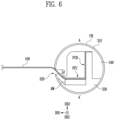
- FIG. 6 is a schematic cross-sectional view illustrating an embodiment of a roller taken along line A-A′ shown in FIG. 3 .
- FIG. 7 is a schematic cross-sectional view illustrating a state in which the display panel is rolled on the roller shown in FIG. 3 .
- the display panel 100 connected to a roller 300 is illustrated together with the roller 300 in FIG. 6 .
- the roller 300 may be disposed inside of the housing 200 to be connected to the display panel 100 (e.g., an end of the display panel 100 ).
- the display panel 100 may be inserted into the housing 200 to be rolled (or wound) on the roller 300 or may be exposed to the outside of the housing to be unrolled from the roller 300 .
- the end of the display panel 100 which is connected to the roller 300 , may correspond to at least a portion of the non-display area of the display 100 described with reference to FIG. 1 .
- the roller 300 may include a rolling member 310 and support members 330 and 340 .
- the rolling member 310 may use, as a center, a rolling axis parallel to the second direction DR 2 , may have a cylindrical shape which is formed to extend in the second direction DR 2 , and may have open end portions.
- the rolling member 310 will be described in more detail with further reference to FIG. 5 .
- the rolling member 310 may serve as a rolling core for rolling the display panel 100 on an outer circumferential surface PH thereof.
- the rolling member 310 may perform a function of a mandrel such that the display panel 100 can be rolled thereon.
- the display panel 100 may be rolled with a curvature radius (e.g., a curvature radius of the rolling member 310 ) in case that the display panel 100 is inserted into the housing 200 to be rolled on the outer circumferential surface PH of the rolling member 310 .
- a curvature radius e.g., a curvature radius of the rolling member 310
- the shape of the rolling member 310 is not limited thereto.
- the rolling member 310 may be implemented in various shapes including a polygonal shape, a semicircular pillar shape, an elliptical pillar shape, or the like.
- the rolling member 310 may have a single body.
- the rolling member 310 may have a single body, and may have a cylindrical shape in which openings OP (e.g., a first opening OPa and a second opening OPb) are formed at both end portions thereof.
- openings OP e.g., a first opening OPa and a second opening OPb
- the openings OP may be areas opened to allow the support members 330 and 340 which will be described later to be coupled to the rolling member 310 by being disposed into an internal empty space of the rolling member 310 .
- a cut-off groove 320 may be formed on at least a portion of the outer circumferential surface PH of the rolling member 310 .
- the cut-off groove 320 obtained by cutting off a portion of the rolling member 310 in the second direction DR 2 may be formed at the outer circumferential surface PH of the rolling member 310 .
- the cut-off groove 320 may be an opening formed at the outer circumferential surface PH of the rolling member 310 such that the display panel 100 is inserted into the rolling member 310 therethrough, in case that a driving circuit board PCB (or connection circuit board FPC) which will be described later and the display panel 100 are electrically connected to each other.
- the rolling member 310 consists of multiple bodies
- a protruding or recessed portion may be formed at a coupling surface of the two semi-cylindrical members.
- An additional protruding or recessed portion may be formed on a groove where a display panel is inserted into.
- the rolling member 310 included in the roller 300 may have a single body as a cylindrical shape.
- any opening or coupling surface is not formed at the outer circumferential surface PH of the rolling member 310 , except an area where the cut-off groove 320 is formed. Therefore, any protruding or recessed area may not be formed at the outer circumferential surface PH of the rolling member 310 . Accordingly, in case that the display panel 100 is rolled (or wound) on the outer circumferential surface PH of the rolling member 310 , damage which may occur in the display panel 100 may be prevented, and thus a defect of pixels may be minimized.
- the rolling member 310 may be formed of a metal material such as aluminum (Al).
- the material of the rolling member 310 is not limited thereto.
- the rolling member 310 may include plastic, rubber, polystyrene, polyvinyl alcohol, polyvinyl chloride, polymethyl methacrylate, polyethersulfone, polyacrylate, polyetherimide, polyethylene naphthalate, polyethylene terephthalate, polyphenylene sulfide, polyarylate, polyimide, polyamide, polycarbonate, triacetate cellulose, cellulose acetate propionate, polypropylene, polyurethane, or a combination thereof.
- a cushion layer (not shown) coated with a fluorine-based resin such as polytetrafluoroethylene (PTFE) may be further disposed on the rolling member 310 so as to reduce friction of the rolling member 310 with the display panel 100 .
- a fluorine-based resin such as polytetrafluoroethylene (PTFE)
- the support members 330 and 340 may include a first support member 330 and a second support member 340 , and may be disposed in the internal empty space of the rolling member 310 to support an inner circumferential surface of the rolling member 310 .
- the support members 330 and 340 may be formed of the substantially same material as the rolling member 310 .
- the material of the support members 330 and 340 is not limited thereto.
- the first support member 330 may be formed to support a portion of the inner circumferential surface of the rolling member 310 .
- the first support member 330 may be in contact with one side surface in the inner circumferential surface of the rolling member 310 , and may support the one side surface.
- the driving circuit board PCB and the connection circuit board FPC for electrically connecting the driving circuit board PCB and the display panel 100 to each other may be disposed on the first support member 330 .
- the first support member 330 may include a protrusion part, and the driving circuit board PCB may be disposed on the protrusion part.
- the driving circuit board PCB may be a board on which driving circuits for providing image data, a control signal, a power voltage, and the like are mounted.
- the driving circuit board PCB may be a flexible wiring board or a rigid wiring board, but the kind of the driving circuit board PCB is not limited thereto.
- connection circuit board FPC may be provided as a film having flexibility, and may be electrically connected to the driving circuit board PCB.
- the connection circuit board FPC may be a flexible printed circuit board (FPCB).
- connection circuit board FPC may be attached to a pad part of the display panel 100 through a film attachment process, to electrically connect the display panel 100 and the driving circuit board PCB to each other.
- An end of the connection circuit board FPC may be electrically connected to the display panel 100 by a conductive adhesive film, and another end of the connection circuit board FPC may be electrically connected to the driving circuit board PCB by the conductive adhesive film.
- the conductive adhesive film may be an anisotropic conductive film (ACF).
- connection circuit board FPC may transfer, to the display panel 100 , the image data, the control signal, the power voltage, and the like, which are supplied from the driving circuit board PCB.
- the display panel 100 may be electrically connected to the connection circuit board FPC in a state that the display panel 100 is inserted into the internal empty space of the rolling member 310 through the cut-off groove 320 of the rolling member 310 .
- a gap (or width) of the cut-off groove 320 of the rolling member 310 may be determined corresponding to the thickness of the display panel 100 .
- a gap d (e.g., a gap or thickness in the third direction DR 3 ) of the cut-off groove 320 may be equal to or greater than the width (or thickness) of the display panel 100 in the third direction DR 3 .
- the gap d (e.g., the gap or thickness in the third direction DR 3 ) of the cut-off groove 320 may be equal to the width (or thickness) of the guide groove 220 in the third direction DR 3 , which is described with reference to FIGS. 1 and 2 .
- An auxiliary member AM may be disposed on the first support member 330 .
- the auxiliary member AM may support an end portion of the display panel 100 where the display panel 100 is electrically connected to the connection circuit board FPC, thereby functioning to fix the display panel 100 .
- the second support member 340 may be formed to support another portion different from the portion supported by the first support member 330 of the inner circumferential surface of the rolling member 310 .
- the second support member 340 may be in contact with the other portion opposite to the portion supported by the first support member 330 of the inner circumferential surface of the rolling member 310 , and may be formed to support the other portion.
- the second support member 340 may be formed to be in contact with the protrusion part of the first support member 330 .
- the first support member 330 and the second support member 340 may be disposed in the internal empty space of the rolling member 310 , to stably support the inner circumferential surface of the rolling member 310 . Thus, an appearance change of the rolling member 310 , and the like may be prevented.
Landscapes
- Engineering & Computer Science (AREA)
- Physics & Mathematics (AREA)
- Theoretical Computer Science (AREA)
- Microelectronics & Electronic Packaging (AREA)
- General Physics & Mathematics (AREA)
- Computer Hardware Design (AREA)
- Optics & Photonics (AREA)
- Human Computer Interaction (AREA)
- General Engineering & Computer Science (AREA)
- Manufacturing & Machinery (AREA)
- Devices For Indicating Variable Information By Combining Individual Elements (AREA)
Abstract
Description
Claims (14)
Applications Claiming Priority (2)
| Application Number | Priority Date | Filing Date | Title |
|---|---|---|---|
| KR1020220002338A KR20230106787A (en) | 2022-01-06 | 2022-01-06 | Display device and fabrication method of display device |
| KR10-2022-0002338 | 2022-01-06 |
Publications (2)
| Publication Number | Publication Date |
|---|---|
| US20230217608A1 US20230217608A1 (en) | 2023-07-06 |
| US12262488B2 true US12262488B2 (en) | 2025-03-25 |
Family
ID=86991460
Family Applications (1)
| Application Number | Title | Priority Date | Filing Date |
|---|---|---|---|
| US17/964,484 Active 2042-12-30 US12262488B2 (en) | 2022-01-06 | 2022-10-12 | Display device and fabrication method of display device |
Country Status (3)
| Country | Link |
|---|---|
| US (1) | US12262488B2 (en) |
| KR (1) | KR20230106787A (en) |
| CN (1) | CN116403479A (en) |
Families Citing this family (1)
| Publication number | Priority date | Publication date | Assignee | Title |
|---|---|---|---|---|
| CN118135901A (en) * | 2024-04-12 | 2024-06-04 | 京东方科技集团股份有限公司 | Display device |
Citations (18)
| Publication number | Priority date | Publication date | Assignee | Title |
|---|---|---|---|---|
| US9098241B1 (en) * | 2014-07-22 | 2015-08-04 | Lg Display Co., Ltd. | Rollable display device |
| KR101570869B1 (en) | 2014-12-31 | 2015-11-23 | 엘지디스플레이 주식회사 | Rollable display apparatus |
| US20160155965A1 (en) * | 2013-06-11 | 2016-06-02 | Empire Technology Development Llc | Display devices and methods of using the same |
| US20170031388A1 (en) * | 2015-07-30 | 2017-02-02 | Lg Display Co., Ltd. | Rollable flexible display device |
| US20170060183A1 (en) * | 2015-08-24 | 2017-03-02 | Apple Inc. | Electronic Devices With Retractable Displays |
| KR101773443B1 (en) | 2014-07-22 | 2017-09-01 | 엘지디스플레이 주식회사 | Rollable display device |
| US20170318688A1 (en) * | 2016-04-29 | 2017-11-02 | Lg Display Co., Ltd. | Rollable Display |
| US20180014415A1 (en) * | 2016-07-06 | 2018-01-11 | Samsung Display Co., Ltd. | Rollable display device |
| US20180070467A1 (en) * | 2016-09-05 | 2018-03-08 | Lg Electronics Inc. | Display device |
| US10362690B2 (en) * | 2016-02-15 | 2019-07-23 | Lg Electronics Inc. | Display apparatus |
| US10535836B2 (en) | 2017-07-31 | 2020-01-14 | Lg Display Co., Ltd. | Display device with rollable display panel |
| US20200107458A1 (en) * | 2018-09-28 | 2020-04-02 | Lg Display Co., Ltd. | Rollable Display Device |
| US20200170114A1 (en) * | 2018-11-28 | 2020-05-28 | Lg Display Co., Ltd. | Display Device |
| US20210272484A1 (en) * | 2020-02-28 | 2021-09-02 | Lg Electronics Inc. | Display device |
| US20210345504A1 (en) * | 2018-09-28 | 2021-11-04 | Sharp Kabushiki Kaisha | Electronic device and container |
| US20220346249A1 (en) * | 2019-07-29 | 2022-10-27 | Lg Electronics Inc. | Rollable display device |
| US20220404872A1 (en) * | 2019-10-25 | 2022-12-22 | Lg Electronics Inc. | Display device |
| US11880240B2 (en) * | 2019-01-25 | 2024-01-23 | Lg Electronics Inc. | Display device |
-
2022
- 2022-01-06 KR KR1020220002338A patent/KR20230106787A/en active Pending
- 2022-10-12 US US17/964,484 patent/US12262488B2/en active Active
-
2023
- 2023-01-05 CN CN202310013940.3A patent/CN116403479A/en active Pending
Patent Citations (20)
| Publication number | Priority date | Publication date | Assignee | Title |
|---|---|---|---|---|
| US20160155965A1 (en) * | 2013-06-11 | 2016-06-02 | Empire Technology Development Llc | Display devices and methods of using the same |
| KR101773443B1 (en) | 2014-07-22 | 2017-09-01 | 엘지디스플레이 주식회사 | Rollable display device |
| US9098241B1 (en) * | 2014-07-22 | 2015-08-04 | Lg Display Co., Ltd. | Rollable display device |
| US9870029B2 (en) | 2014-12-31 | 2018-01-16 | Lg Display Co., Ltd. | Rollable display apparatus |
| KR101570869B1 (en) | 2014-12-31 | 2015-11-23 | 엘지디스플레이 주식회사 | Rollable display apparatus |
| US20170031388A1 (en) * | 2015-07-30 | 2017-02-02 | Lg Display Co., Ltd. | Rollable flexible display device |
| US20170060183A1 (en) * | 2015-08-24 | 2017-03-02 | Apple Inc. | Electronic Devices With Retractable Displays |
| US10362690B2 (en) * | 2016-02-15 | 2019-07-23 | Lg Electronics Inc. | Display apparatus |
| US20170318688A1 (en) * | 2016-04-29 | 2017-11-02 | Lg Display Co., Ltd. | Rollable Display |
| US20180014415A1 (en) * | 2016-07-06 | 2018-01-11 | Samsung Display Co., Ltd. | Rollable display device |
| US20180070467A1 (en) * | 2016-09-05 | 2018-03-08 | Lg Electronics Inc. | Display device |
| US10535836B2 (en) | 2017-07-31 | 2020-01-14 | Lg Display Co., Ltd. | Display device with rollable display panel |
| KR102332810B1 (en) | 2017-07-31 | 2021-11-29 | 엘지디스플레이 주식회사 | Rollable display device |
| US20200107458A1 (en) * | 2018-09-28 | 2020-04-02 | Lg Display Co., Ltd. | Rollable Display Device |
| US20210345504A1 (en) * | 2018-09-28 | 2021-11-04 | Sharp Kabushiki Kaisha | Electronic device and container |
| US20200170114A1 (en) * | 2018-11-28 | 2020-05-28 | Lg Display Co., Ltd. | Display Device |
| US11880240B2 (en) * | 2019-01-25 | 2024-01-23 | Lg Electronics Inc. | Display device |
| US20220346249A1 (en) * | 2019-07-29 | 2022-10-27 | Lg Electronics Inc. | Rollable display device |
| US20220404872A1 (en) * | 2019-10-25 | 2022-12-22 | Lg Electronics Inc. | Display device |
| US20210272484A1 (en) * | 2020-02-28 | 2021-09-02 | Lg Electronics Inc. | Display device |
Also Published As
| Publication number | Publication date |
|---|---|
| KR20230106787A (en) | 2023-07-14 |
| US20230217608A1 (en) | 2023-07-06 |
| CN116403479A (en) | 2023-07-07 |
Similar Documents
| Publication | Publication Date | Title |
|---|---|---|
| CN114627766B (en) | Display device | |
| CN111161633B (en) | Display device | |
| TWI421608B (en) | A device comprising a multilayer structure with a first portion and a second portion | |
| CN107895541B (en) | Display device | |
| CN111462621B (en) | Slidable display device | |
| US9629237B2 (en) | Rollable display device | |
| KR102113963B1 (en) | Expandable mobile device | |
| US9747822B2 (en) | Rollable display device | |
| US12262488B2 (en) | Display device and fabrication method of display device | |
| CN116386458B (en) | Display device | |
| JP2016130853A (en) | Rollable display device | |
| CN113056899A (en) | Scrolling display device for electronic apparatus | |
| CN110164304A (en) | foldable display device | |
| US20210034106A1 (en) | Display device | |
| CN111833751B (en) | Supporting plate, folding display panel and folding display device | |
| CN212256772U (en) | Display device | |
| CN114694499A (en) | Foldable display device | |
| US11806975B2 (en) | Display apparatus | |
| US20240107692A1 (en) | Display device | |
| CN114677915B (en) | Display device | |
| CN116343593A (en) | Display device and method of manufacturing the same | |
| US20240373732A1 (en) | Display device | |
| KR20080008220A (en) | Fine Pattern Film Manufacturing Equipment | |
| CN220020506U (en) | Display device | |
| US12464880B2 (en) | Display device |
Legal Events
| Date | Code | Title | Description |
|---|---|---|---|
| AS | Assignment |
Owner name: SAMSUNG DISPLAY CO., LTD., KOREA, REPUBLIC OF Free format text: ASSIGNMENT OF ASSIGNORS INTEREST;ASSIGNORS:PARK, DONG JIN;SIM, JIN GYU;JIN, BYOUNG JIN;SIGNING DATES FROM 20220630 TO 20220704;REEL/FRAME:061663/0429 |
|
| FEPP | Fee payment procedure |
Free format text: ENTITY STATUS SET TO UNDISCOUNTED (ORIGINAL EVENT CODE: BIG.); ENTITY STATUS OF PATENT OWNER: LARGE ENTITY |
|
| STPP | Information on status: patent application and granting procedure in general |
Free format text: DOCKETED NEW CASE - READY FOR EXAMINATION |
|
| STPP | Information on status: patent application and granting procedure in general |
Free format text: NON FINAL ACTION MAILED |
|
| STPP | Information on status: patent application and granting procedure in general |
Free format text: NON FINAL ACTION MAILED |
|
| STPP | Information on status: patent application and granting procedure in general |
Free format text: RESPONSE TO NON-FINAL OFFICE ACTION ENTERED AND FORWARDED TO EXAMINER |
|
| STPP | Information on status: patent application and granting procedure in general |
Free format text: FINAL REJECTION MAILED |
|
| STPP | Information on status: patent application and granting procedure in general |
Free format text: RESPONSE AFTER FINAL ACTION FORWARDED TO EXAMINER |
|
| STPP | Information on status: patent application and granting procedure in general |
Free format text: NOTICE OF ALLOWANCE MAILED -- APPLICATION RECEIVED IN OFFICE OF PUBLICATIONS |
|
| STPP | Information on status: patent application and granting procedure in general |
Free format text: AWAITING TC RESP., ISSUE FEE NOT PAID |
|
| STPP | Information on status: patent application and granting procedure in general |
Free format text: NOTICE OF ALLOWANCE MAILED -- APPLICATION RECEIVED IN OFFICE OF PUBLICATIONS |
|
| STPP | Information on status: patent application and granting procedure in general |
Free format text: PUBLICATIONS -- ISSUE FEE PAYMENT VERIFIED |
|
| STCF | Information on status: patent grant |
Free format text: PATENTED CASE |