US12259315B2 - Ultrasonic transducer holder, container, and analysis system using same - Google Patents
Ultrasonic transducer holder, container, and analysis system using same Download PDFInfo
- Publication number
- US12259315B2 US12259315B2 US18/015,369 US202018015369A US12259315B2 US 12259315 B2 US12259315 B2 US 12259315B2 US 202018015369 A US202018015369 A US 202018015369A US 12259315 B2 US12259315 B2 US 12259315B2
- Authority
- US
- United States
- Prior art keywords
- ultrasonic transducer
- container
- protective layer
- contact medium
- transducer holder
- Prior art date
- Legal status (The legal status is an assumption and is not a legal conclusion. Google has not performed a legal analysis and makes no representation as to the accuracy of the status listed.)
- Active, expires
Links
Images


Classifications
-
- G—PHYSICS
- G01—MEASURING; TESTING
- G01N—INVESTIGATING OR ANALYSING MATERIALS BY DETERMINING THEIR CHEMICAL OR PHYSICAL PROPERTIES
- G01N21/00—Investigating or analysing materials by the use of optical means, i.e. using sub-millimetre waves, infrared, visible or ultraviolet light
- G01N21/01—Arrangements or apparatus for facilitating the optical investigation
- G01N21/03—Cuvette constructions
-
- G—PHYSICS
- G01—MEASURING; TESTING
- G01N—INVESTIGATING OR ANALYSING MATERIALS BY DETERMINING THEIR CHEMICAL OR PHYSICAL PROPERTIES
- G01N21/00—Investigating or analysing materials by the use of optical means, i.e. using sub-millimetre waves, infrared, visible or ultraviolet light
- G01N21/17—Systems in which incident light is modified in accordance with the properties of the material investigated
- G01N21/25—Colour; Spectral properties, i.e. comparison of effect of material on the light at two or more different wavelengths or wavelength bands
- G01N21/31—Investigating relative effect of material at wavelengths characteristic of specific elements or molecules, e.g. atomic absorption spectrometry
-
- G—PHYSICS
- G01—MEASURING; TESTING
- G01N—INVESTIGATING OR ANALYSING MATERIALS BY DETERMINING THEIR CHEMICAL OR PHYSICAL PROPERTIES
- G01N29/00—Investigating or analysing materials by the use of ultrasonic, sonic or infrasonic waves; Visualisation of the interior of objects by transmitting ultrasonic or sonic waves through the object
- G01N29/02—Analysing fluids
- G01N29/036—Analysing fluids by measuring frequency or resonance of acoustic waves
-
- G—PHYSICS
- G01—MEASURING; TESTING
- G01N—INVESTIGATING OR ANALYSING MATERIALS BY DETERMINING THEIR CHEMICAL OR PHYSICAL PROPERTIES
- G01N29/00—Investigating or analysing materials by the use of ultrasonic, sonic or infrasonic waves; Visualisation of the interior of objects by transmitting ultrasonic or sonic waves through the object
- G01N29/22—Details, e.g. general constructional or apparatus details
- G01N29/222—Constructional or flow details for analysing fluids
-
- G—PHYSICS
- G01—MEASURING; TESTING
- G01N—INVESTIGATING OR ANALYSING MATERIALS BY DETERMINING THEIR CHEMICAL OR PHYSICAL PROPERTIES
- G01N29/00—Investigating or analysing materials by the use of ultrasonic, sonic or infrasonic waves; Visualisation of the interior of objects by transmitting ultrasonic or sonic waves through the object
- G01N29/22—Details, e.g. general constructional or apparatus details
- G01N29/24—Probes
- G01N29/2418—Probes using optoacoustic interaction with the material, e.g. laser radiation, photoacoustics
-
- G—PHYSICS
- G01—MEASURING; TESTING
- G01N—INVESTIGATING OR ANALYSING MATERIALS BY DETERMINING THEIR CHEMICAL OR PHYSICAL PROPERTIES
- G01N21/00—Investigating or analysing materials by the use of optical means, i.e. using sub-millimetre waves, infrared, visible or ultraviolet light
- G01N21/01—Arrangements or apparatus for facilitating the optical investigation
- G01N21/03—Cuvette constructions
- G01N2021/0367—Supports of cells, e.g. pivotable
Definitions
- the present invention relates to an ultrasonic transducer holder, a container, and an analysis system using these.
- JP2019-211235A (PTL 1) describes an analysis cell for accommodating a liquid sample that is detachably replaceable with respect to an analysis unit. Further, PTL 1 describes that an ultrasonic transducer and a wall surface of the analysis cell are brought into close contact with each other via a gel substance.
- An object of the invention is to provide a technique for suppressing deterioration in analysis accuracy in an analysis system in which a container for accommodating a liquid sample is detachable from an ultrasonic transducer holder.
- an ultrasonic transducer holder which is an embodiment, has a detachable container for containing a liquid sample, and transmits an ultrasonic wave.
- the ultrasonic transducer holder includes an ultrasonic transducer that emits an ultrasonic wave, and a protective layer that is fixed to the ultrasonic transducer and transmits the ultrasonic wave to the container.
- the protective layer includes a first surface that is a surface to which the ultrasonic transducer is fixed, and a second surface that is a back surface of the first surface and is designed to fix the container via a contact medium.
- An analysis system which is another embodiment, includes the ultrasonic transducer holder, an oscillator that applies voltage to the ultrasonic transducer, a light source that irradiates the container with a light ray, a light receiving portion that receives a light ray transmitted through the container, and a computer that performs analysis processing of the liquid sample based on the light ray received by the light receiving portion.
- the ultrasonic transducer holder has a detachable container for containing a liquid sample, and transmits an ultrasonic wave.
- the ultrasonic transducer holder includes an ultrasonic transducer that emits an ultrasonic wave, and a protective layer that is fixed to the ultrasonic transducer and transmits the ultrasonic wave to the container.
- the protective layer includes a first surface that is a surface to which the ultrasonic transducer is fixed, and a second surface that is a back surface of the first surface and is designed to fix the container via a contact medium.
- a container which is still another embodiment, is a container that is detachable from the ultrasonic transducer holder.
- the ultrasonic transducer holder has a detachable container for containing a liquid sample, and transmits an ultrasonic wave.
- the ultrasonic transducer holder includes an ultrasonic transducer that emits an ultrasonic wave, and a protective layer that is fixed to the ultrasonic transducer and transmits the ultrasonic wave to the container.
- the protective layer includes a first surface that is a surface to which the ultrasonic transducer is fixed, and a second surface that is a back surface of the first surface and is designed to fix the container via a contact medium.
- the second surface has an application region mark that is a mark indicating an application region of the contact medium.
- the container includes a side surface having a shape corresponding to the application region, an inlet for feeding the liquid sample, and an outlet for discharging the liquid sample.
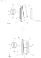
- FIG. 1 is a front view illustrating a state in which a container is attached to an ultrasonic transducer holder that is an embodiment of the present invention.
- FIG. 2 is a side view of the ultrasonic transducer holder illustrated in FIG. 1 as viewed from an ultrasonic transducer side.
- FIG. 3 is a plan view illustrating a first surface of a protective layer illustrated in FIG. 1 .
- FIG. 4 is a front view illustrating an ultrasonic transducer holder having a modification example of the protective layer illustrated in FIG. 1 and a container.
- FIG. 5 is a cross-sectional view illustrating a cross section cut parallel to an X-Y plane along the line A-A illustrated in FIG. 4 .
- FIG. 6 is a plan view illustrating a second surface of the protective layer illustrated in FIG. 3 .
- FIG. 7 is a plan view illustrating a second surface of a protective layer of the ultrasonic transducer holder which is a modification example to FIG. 6 .
- FIG. 8 is an explanatory view illustrating steps of fixing the container to the ultrasonic transducer holder provided with the protective layer illustrated in FIG. 7 .
- FIG. 10 is a front view illustrating a configuration example of an ultrasonic transducer holder that is a modification example to FIGS. 8 and 9 .
- FIG. 14 is a front view illustrating a modification example to FIG. 12 .
- FIG. 15 is a top view schematically illustrating how a contact medium is supplied to a recess of a protective layer illustrated in FIG. 14 .
- FIG. 19 is a side view of the ultrasonic transducer holder illustrated in FIG. 18 as viewed from an ultrasonic transducer side.
- FIG. 20 is an explanatory view illustrating a process flow of an analysis method using the analysis system illustrated in FIGS. 18 and 19 .
- the protective layer 11 is interposed between the container 13 and the ultrasonic transducer 10 .
- the protective layer 11 is fixed to the ultrasonic transducer 10 .
- the protective layer 11 is not attached or detached from the ultrasonic transducer 10 . Therefore, contact or collision between the container 13 and the ultrasonic transducer 10 can be avoided during attachment/detachment work. Therefore, risks such as wear and damage of the ultrasonic transducer 10 can be avoided.
- the contact medium 12 is applied not to the ultrasonic transducer 10 but to the protective layer 11 .
- the protective layer 11 has a function of transmitting the ultrasonic waves output by the ultrasonic transducer 10 to the container 13 . As a result, ultrasonic waves can be applied to the container 13 without bringing the ultrasonic transducer 10 and the container 13 into direct contact with each other.
- first surface 11 A and the second surface 11 B of the protective layer 11 are preferably parallel to each other.
- one or both of the first surface 11 A and the second surface 11 B of the protective layer 11 may not be planar.
- the first surface 11 A and the second surface 11 B of the protective layer 11 may not be arranged in parallel.
- a constituent material of the container 13 for containing the liquid sample 201 is desirably one that easily transmits a light ray used in spectroscopic analysis. Moreover, it is more desirable that the constituent material of the container 13 is chemically stable and has mechanical strength and heat resistance.
- a spectroscopic analysis cell or cuvette is used as the container 13 .
- constituent materials for the cell and cuvette include quartz, glass, acrylic resin, polystyrene resin, and polycarbonate resin, and from these materials, a suitable material can be selected according to the type of the liquid sample 201 from the viewpoint of the above-described light transmittance, chemical stability, mechanical strength, heat resistance, and the like. In the example illustrated in FIG.
- the container 13 has a side surface 13 A facing the second surface 11 B of the protective layer 11 .
- the side surface 13 A is a surface that is pressed against the protective layer 11 via the contact medium 12 , and is typically a flat surface (a non-curved surface).
- the second surface 11 B of the protective layer 11 and the side surface 13 A of the container 13 are each flat and face each other, the transmission characteristics of ultrasonic waves from the protective layer 11 to the container 13 can be improved.
- the thickness (for details, the thickness of the fixing region 11 R 1 in a direction of the extension of the attachment surface 10 A of the ultrasonic transducer in the normal direction of the protective layer 11 ) of the protective layer 11 is preferably 0.5 times or more and 10 times or less of the half wavelength of the ultrasonic wave in the protective layer 11 .
- the transmission characteristics of ultrasonic waves in the protective layer 11 are more affected by the thickness of the fixing region 11 R 1 than the thickness of the peripheral region 11 R 2 . Therefore, a structure in which the fixing region 11 R 1 , which has a large influence on the transmission characteristics of the ultrasonic waves, is selectively thin in the protective layer 11 , and the peripheral region 11 R 2 (see FIG. 3 ), which requires high rigidity as a support structure, is thicker than the fixing region 11 R 1 is preferable.
- the pressing structure 14 has a mechanism for pressing the pressed surface 13 B of the container 13 in the direction (hereinafter referred to as the ⁇ Y direction) opposite to the Y direction.
- the container 13 pressed by the pressing structure 14 is pressed against the second surface 11 B of the protective layer 11 via the contact medium 12 .
- the side surface 13 A of the container 13 pressed against the protective layer 11 is typically planar.
- the fixing structure for fixing the container 13 to the protective layer 11 via the contact medium 12 must make the container detachable. Therefore, this fixing structure does not adhere and fix the protective layer 11 and the container 13 with the adhesive 15 , but fixes the container 13 so that it is not displaced during use.
- a metal plate, a metal block, a metal rod, a spring, a bolt, a rubber plate, a resin plate, a resin block, a resin rod, and the like can be exemplified as the pressing structure 14 as an example of the fixing structure.
- a structure obtained by combining the members described above can be used as the pressing structure 14 .
- the following method can be exemplified.
- the pressing structure 14 formed of a metal plate, a metal block, a metal rod, a spring, a bolt, a rubber plate, a resin plate, a resin block, a resin rod, and the like is brought into contact with the container 13 and the container 13 is pressed and fixed against the protective layer 11 using the elasticity of the material forming the pressing structure 14 or the reaction of force.
- a driving force for pressing the pressing structure 14 against the container 13 include air pressure, water pressure, hydraulic pressure, and electromagnetic force.
- the fixing structure for fixing the container 13 includes various modification examples other than the pressing structure 14 illustrated in FIG. 1 .
- the fixing structure should be able to bring the container 13 and the ultrasonic transducer holder 101 into close contact and separate them.
- the protective layer 11 and the ultrasonic transducer 10 of the ultrasonic transducer holder 101 and the container 13 are independently held and independently transportable by a transport mechanism portion.
- the container 13 and the ultrasonic transducer holder 101 can be brought into close contact with each other by operating the transport mechanism portion, and can be separated from each other, so that it can be used as a fixing structure.
- FIG. 4 is a front view of an ultrasonic transducer holder having a modification example of the protective layer illustrated in FIG. 1 and a container.
- FIG. 5 is a cross-sectional view illustrating a cross section cut parallel to the X-Y plane along the line A-A illustrated in FIG. 4 .
- the modification example differs from the embodiment illustrated in FIG. 1 in that a thickness 11 T 1 (see FIG. 4 ) of the fixing region 11 R 1 of the protective layer 11 is thinner than a thickness 11 T 2 of the peripheral region 11 R 2 .
- the protective layer 11 has a recess portion (groove, hole) 11 H formed at a position overlapping the fixing region 11 R 1 .
- the recess portion 11 H is a hole dug from the first surface 11 A side of the protective layer 11 toward the second surface 11 B side.
- the recess portion 11 H does not penetrate the protective layer 11 in a thickness direction (a direction from one of the first surface 11 A and the second surface 11 B to the other).
- a bottom surface 11 G of the recess portion 11 H is typically flat. At least a part of the ultrasonic transducer 10 is inserted into the recess portion 11 H and adhered and fixed to the bottom surface 11 G of the recess portion 11 H via the adhesive 15 (see FIG. 4 ).
- the bottom surface 11 G can be regarded as a part of the first surface 11 A of the protective layer 11 .
- the thickness 11 T 1 (see FIG. 4 ) of a portion interposed between the bottom surface 11 G and the second surface 11 B is thinner than the thickness 11 T 2 of a portion belonging to the peripheral region 11 R 2 .
- the portion interposed between the bottom surface 11 G and the second surface 11 B includes the entirety of the fixing region 11 R 1 .
- the fixing region 11 R 1 is defined as a region that extends the attachment surface 10 A of the ultrasonic transducer 10 in the normal direction.
- the bottom surface 11 G includes the entirety of the fixing region 11 R 1 and a part of the peripheral region 11 R 2 .
- an area of the portion belonging to the peripheral region 11 R 2 is so small that it can be ignored compared to an area of the portion belonging to the fixing region 11 R 1 . Therefore, substantially, the bottom surface 11 G of the recess portion 11 H can be regarded as belonging to the fixing region 11 R 1 .
- the thickness 11 T 1 (see FIG. 4 ) of the fixing region 11 R 1 that contributes to the transmission of ultrasonic waves is thinner than the thickness of the peripheral region 11 R 2 , so the degree of attenuation of ultrasonic waves by the protective layer 11 can be reduced.
- the thickness 11 T 2 of the peripheral region 11 R 2 of the protective layer 11 can be increased.
- the peripheral region 11 R 2 of the protective layer 11 is arranged like a frame around the ultrasonic transducer 10 . As a result, the rigidity of the entirety of the ultrasonic transducer holder 101 including the ultrasonic transducer 10 and the protective layer 11 can be increased.
- the surface condition of the bottom surface 11 G to which the ultrasonic transducer 10 is attached is preferably a flattened surface.
- the adhesive 15 see FIG. 4
- the adhesive 15 since the adhesive 15 is embedded even when there is some surface roughness, it is possible to suppress deterioration in the transmission characteristics of ultrasonic waves due to the rough surface condition.
- FIG. 6 is a plan view illustrating the second surface of the protective layer illustrated in FIG. 3 .
- FIG. 6 is a plan view illustrating the second surface 11 B of the protective layer 11 .
- a region (a region corresponding to the fixing region 11 R 1 in FIG.
- each of the fixing region 11 R 1 and the peripheral region 11 R 2 is defined not as a plane but as a three-dimensional portion extending in the Y direction illustrated in FIG. 1 , but the region 11 R 3 is defined as a surface of the region 11 R 1 that intersects the second surface 11 B.
- the application region 12 R is a region to which the contact medium 12 is to be supplied, and a slight error is allowed between it and a region where the contact medium 12 is actually arranged.
- the second surface 11 B of the protective layer 11 is provided with an application region mark 20 that is a mark indicating the application region 12 R of the contact medium 12 (see FIG. 1 ). Since the protective layer 11 is provided with the application region mark 20 , when a supply position of the contact medium 12 is displaced, it is possible to visually (optically when using an image sensor, or the like) detect the occurrence of the displacement and the degree of the displacement.
- the application region mark 20 can be visually (optically) recognized when the supply position of the contact medium 12 is displaced.
- a method of thinly shaving the second surface 11 B of the protective layer 11 along an outer edge of the application region 12 R to form a marking line can be exemplified.
- a method of forming the application region mark 20 by printing it on the second surface 11 B may be applied.
- the unevenness of the second surface 11 B of the protective layer 11 can be kept small, so it is preferable from the viewpoint of suppressing the deterioration of the transmission characteristics of ultrasonic waves.
- FIG. 6 illustrates an example in which the application region mark 20 having a frame shape is formed along the outer edge of the application region 12 R.
- the application region mark 20 may be partially formed along the outer edge of the application region 12 R.
- a method of forming the application region mark 20 at least at two or more diagonal corners of four corners of the quadrangle, a method of forming the application region mark 20 on each of the four sides, or a method of forming the application region marks 20 on, in addition to the four corners, each side between adjacent corners can be exemplified.
- the contact medium 12 illustrated in FIGS. 1 and 4 is applied within a range of the application region mark 20 illustrated in FIG. 6 .
- an application method for example, there is a method in which the contact medium 12 (see FIG. 1 ) is spread and applied onto the second surface 11 B of the protective layer 11 using an application jig such as a brush, a cotton swab, a cloth, or a roller.
- the contact medium 12 may be applied by flowing or spraying it from a nozzle (not illustrated).
- there is a method or transferring the contact medium 12 by attaching a plate-shaped transfer jig having a transfer surface pre-coated with the contact medium 12 to the application region 12 R.
- a sponge impregnated with the contact medium 12 may be used as the transfer jig described above.
- the application region 12 R is a region that includes the region 11 R 3 where the space obtained by extending the ultrasonic transducer 10 (see FIG. 1 ; the attachment surface 10 A of the ultrasonic transducer 10 for details) in the normal direction and the second surface 11 B intersect.
- Ultrasonic waves are transmitted from the fixing region 11 R 1 (see FIG. 3 ) and transmitted from the protective layer 11 to the container 13 (see FIG. 1 ) via the application region 12 R. Therefore, as illustrated in FIG. 6 , by arranging the application region 12 R at a position that includes the fixing region 11 R 3 , which is the surface opposite to the fixing region 11 R 1 , the transmission path of the ultrasonic waves can be arranged linearly.
- FIG. 6 As a modification example to FIG.
- a part of the fixing region 11 R 3 may not be included in the application region 12 R.
- the configuration illustrated in FIG. 6 can be expressed as follows. That is, the application region 12 R is a region that includes a region (fixing region 11 R 3 ) where the space extending the ultrasonic transducer 10 (see FIG. 1 ) and the second surface 11 B intersect in the traveling direction of ultrasonic waves.
- the transmission path of the ultrasonic waves can be arranged linearly, so that the transmission of the ultrasonic waves can be made more efficient.
- FIG. 7 is a plan view illustrating a second surface of a protective layer of the ultrasonic transducer holder which is a modification example to FIG. 6 .
- FIG. 8 is an explanatory view illustrating steps of fixing the container to the ultrasonic transducer holder provided with the protective layer illustrated in FIG. 7 .
- FIG. 9 is an explanatory view illustrating steps that are a modification example to FIG. 8 .
- an ultrasonic transducer holder 101 A differs from the ultrasonic transducer holder 101 illustrated in FIGS. 1 and 4 in that it has a guide member 21 that guides the fixing of the container 13 (see FIGS. 8 and 9 ) to the application region 12 R (see FIG. 7 ).
- illustration of the inlet 131 and the outlet 132 illustrated in FIG. 1 is omitted.
- the liquid sample 201 illustrated in FIG. 1 is not illustrated because the container 13 is fixed before the liquid sample 201 illustrated in FIG. 1 is supplied into the container 13 .
- the contact medium 12 is applied in advance on the second surface 11 B of the protective layer 11 as illustrated in FIG. 8 , for example. Then, the container 13 is pressed against the protective layer 11 along the guide member 21 .
- the contact medium 12 is applied in advance onto the side surface 13 A of the container 13 . Then, the container. 13 is pressed against the protective layer 11 along the guide member 21 .
- the container 13 it is preferable that the container 13 have an application region mark.
- the method of applying the contact medium 12 to the container 13 is the same as the method of applying the contact medium 12 to the application region 12 R of the protective layer 11 described with reference to FIG. 6 .
- the guide member 21 is fixed to the protective layer 11 . Since the ultrasonic transducer holder 101 is provided with the guide member 21 , it is possible to improve the accuracy of the position to which the container is pressed, thereby preventing displacement of the container 13 due to repeated mounting work. In addition, when the guide member 21 is used, there is no need for visual trial and error in the work of pressing the container 13 . Therefore, the work of pressing the container 13 can be made more efficient.
- the guide member 21 is an L-shaped metal fitting.
- the guide member 21 is made of a material that can guide the position of the container 13 when the container 13 is pressed against the protective layer 11 .
- a pin having a shape such as a U shape, a cylindrical shape, or a prism shape can be exemplified.
- the fixing positions of the guide members 21 it is preferable that at least one or more guide members 21 be fixed around the application region 12 R illustrated in FIG. 7 .
- a plurality of guide members 21 be formed around the application region 12 R.
- the number of portions of which positions are restricted by the guide members 21 is small. Therefore, for example, as illustrated in FIG. 7 , when the application region 12 R forms a quadrangle in a plan view, for example, a structure in which the guide members 21 are respectively fixed to the corners at both ends of one side of the quadrangle and the guide members 21 are not fixed to an opposite side is also conceivable. In this case, the degree of freedom in selecting the container 13 is improved.
- FIGS. 10 and 11 illustrate a modification example of the guide member 21 .
- FIG. 10 is a front view illustrating a configuration example of an ultrasonic transducer holder that is a modification example to FIGS. 8 and 9 .
- FIG. 11 is a cross-sectional view illustrating a cross-section cut parallel to the X-Y plane along line A-A of FIG. 10 .
- the ultrasonic transducer holder 101 B illustrated in FIG. 10 is different from the ultrasonic transducer holder 101 A illustrated in FIG. 8 in that the guide member 21 includes a recess portion 21 A formed from the second surface 11 B of the protective layer 11 toward the first surface 11 A, and a convex portion 21 B formed on the side surface 13 A of the container 13 .
- the recess portion 21 A and the convex portion 21 B have mutually corresponding shapes (shapes that can be engaged with a clearance that allows the convex portion 21 B to be inserted into the recess portion 21 A).
- the side surface 13 A of the container 13 is pushed toward the second surface 11 B or the protective layer 11 , as schematically illustrated with an arrow in FIG. 11 , the convex portion 21 B is inserted into the recess portion 21 A.
- the container 13 and the protective layer 11 can be aligned with high accuracy in the same manner as the guide member 21 described with reference to FIGS. 8 and 9 .
- alignment work can be performed efficiently.
- the modification example illustrated in FIGS. 10 and 11 can be expressed as follows. That is, the container 13 has a shape (convex portion 21 B) corresponding to the shape of the guide member (recess portion 21 A).
- FIGS. 10 and 11 an example in which the rectangular parallelepiped convex portion 21 B is formed on the container 13 and the rectangular parallelepiped recess portion 21 A formed on the protective layer 11 is described, but there are various modification examples of the method of positioning the container 13 according to the shapes of the container 13 and the protective layer 11 .
- the convex portion 21 B and the recess portion 21 A may have various shapes such as a rectangular parallelepiped shape, a prism, a cylinder, a pyramid, and a hemisphere.
- the convex portion 21 B may be formed on the second surface 11 B side of the protective layer 11 and the recess portion 21 A corresponding to the convex portion 21 B may be formed on the side surface 13 A side of the container 13 .
- each of the second surface 11 B of the protective layer 11 and the side surface 13 A of the container 13 is a flat surface, it can be considered as one aspect indicating that the shape of the side surface 13 A of the container 13 is a shape corresponding to the shape of the application region 12 R of the protective layer 11 .
- the recess portion 21 A may be formed on the pressing structure 14 side.
- the contact medium 12 (see FIGS. 8 to 11 ) can be reliably interposed between the application region 12 R (see FIGS. 6 and 7 ) of the protective layer 11 and the container 13 .
- the entirety of the side surface 13 A of the container 13 be fixed to the application region 12 R, when at least a part of the side surface 13 A is fixed to the application region 12 R, ultrasonic waves are transmitted into the container 13 through the part fixed to the application region 12 R.
- FIG. 12 is a front view illustrating a protective layer provided in a modification example of the ultrasonic transducer holder illustrated in FIG. 1 and a container fixed in a vicinity of the protective layer.
- FIG. 13 is a top view schematically illustrating how a contact medium is supplied to a recess of the protective layer illustrated in FIG. 12 .
- FIG. 14 is a front view illustrating a modification example to FIG. 12 .
- FIG. 15 is a top view schematically illustrating how a contact medium is supplied to a recess of a protective layer illustrated in FIG. 14 .
- an outline of a recess 31 formed in the second surface 11 B of the protective layer 11 and a plurality of pores 32 communicating from the surface of the protective layer 11 to the recess 31 are indicated by dotted lines.
- Each of an ultrasonic transducer holder 101 C illustrated in FIGS. 12 and 13 and an ultrasonic transducer holder 101 D illustrated in FIGS. 14 and 15 differs from the ultrasonic transducer holder 101 illustrated in FIG. 1 in that it has the recess 31 and the pores 32 for supplying the contact medium 12 .
- Each of the ultrasonic transducer holder 101 C and the ultrasonic transducer holder 101 D has a first pore 32 A (see FIGS. 13 to 15 ) for filling the contact medium 12 (see FIGS. 13 and 14 ), and the recess 31 in contact with the second surface 11 B of the protective layer 11 and designed to be filled with the contact medium 12 as the application region 12 R.
- each of the ultrasonic transducer holder 101 C and the ultrasonic transducer holder 101 D has a second pore 32 B for discharging the air (gas) or contact medium 12 remaining in the recess.
- the second pore 32 B as a discharge port in addition to the first pore 32 A as a supply port, the generation of air bubbles in a space surrounded by the recess 31 and the container 13 can be suppressed.
- FIGS. 12 to 15 show examples in which the contact medium 12 is supplied after the container 13 is pressed. However, as a modification example, the container 13 may be pressed after the recess 31 is filled with the contact medium 12 .
- the protective layer 11 provided in each of the ultrasonic transducer holder 101 C and the ultrasonic transducer holder 101 D has a third surface (side surface) 11 C continuous with the second surface 11 B, a fourth surface (side surface) 11 D opposite to the third surface, the second surface 11 B, a fifth surface (upper surface) 11 E continuous with the third surface 11 C and the fourth surface 11 D, and a sixth surface (lower surface) 11 F opposite to the fifth surface 11 E.
- the recess 31 is a recess portion provided on the second surface 11 B of the protective layer 11 . It is preferable that an opening area (an area of the opening in the second surface 11 B) of the recess 31 be equal to or larger than an area of a region in the container 13 where it is desired to form an aggregation layer by ultrasonic waves.
- the container 13 is a cell for spectroscopic analysis
- an outer thickness (a length of the container 13 in the X direction, in other words, a distance from a position where a light beam from a light source is incident on the container 13 to a position where the light beam is emitted from the container 13 ) of the container 13 is 3 mm
- a total height is 45 mm
- an optical path length (a distance that the light beam from the light source passes through the liquid sample 201 in the container 13 ) is 1 mm
- a length of the aggregation layer in the container 13 in the Z direction (height direction) is 10 mm.
- an opening portion of the recess 31 preferably has a width (length in the X direction) of 1 mm to 3 mm and a length in a height direction (Z direction) of 10 mm to 45 mm. Further, a depth (length in the Y direction) of the recess 31 is preferably as shallow as possible within a range where the contact medium 12 can flow. For example, the depth of the recess 31 is preferably in a range of 0.01 mm to 0.5 mm.
- a pore size of each of the plurality of pores 32 including the first pore 32 A and the second pore 32 B can be determined in consideration of the workability of forming pores and the fluidity of the contact medium 12 .
- the pore size of each of the plurality of pores 32 is within a range of 0.1 mm to 1 mm.
- the ultrasonic waves radiated from the ultrasonic transducer 10 into the container 13 are reflected on the plane of the container 13 .
- a standing wave is formed in the container 13 when the frequency of the ultrasonic wave is adjusted to a specific frequency.
- the suspended matters in the liquid sample 201 are gathered at the nodes or antinodes of the standing wave by an acoustic radiation force of the ultrasonic waves, and an aggregation layer 56 is periodically formed.
Landscapes
- Physics & Mathematics (AREA)
- Immunology (AREA)
- Health & Medical Sciences (AREA)
- Chemical & Material Sciences (AREA)
- Analytical Chemistry (AREA)
- Biochemistry (AREA)
- General Health & Medical Sciences (AREA)
- Life Sciences & Earth Sciences (AREA)
- Pathology (AREA)
- General Physics & Mathematics (AREA)
- Spectroscopy & Molecular Physics (AREA)
- Acoustics & Sound (AREA)
- Optics & Photonics (AREA)
- Investigating Or Analyzing Materials By The Use Of Ultrasonic Waves (AREA)
- Optical Measuring Cells (AREA)
- Investigating Or Analysing Materials By Optical Means (AREA)
Abstract
Description
-
- PTL 1: JP2019-211235A
-
- 10: ultrasonic transducer
- 10A: attachment surface
- 11: protective layer
- 11A: first surface
- 11B: second surface
- 11C: third surface (side surface)
- 11D: fourth surface (side surface)
- 11E: fifth surface (upper surface)
- 11F: sixth surface (lower surface)
- 11G: bottom surface
- 11H: recess portion (groove, hole)
- 11R1, 11R3: fixing region
- 11R2: peripheral region
- 11T1, 11T2: thickness
- 12: contact medium
- 12R: application region
- 13: container
- 13A: side surface
- 13B: pressed surface
- 14: pressing structure (pressing member)
- 15: adhesive
- 20: application region mark
- 20: application region
- 21: guide member
- 21A: recess portion
- 21B: convex portion
- 31: recess
- 32: pore
- 32A: first pore
- 32B: second pore
- 33: injector (syringe)
- 34: pressure sensor
- 35: pipe
- 41: roller
- 42: nozzle
- 50: oscillator
- 51: light source
- 52: light receiving portion
- 53: computer
- 54: spectroscopic analysis portion
- 55: light beam
- 56: aggregation layer
- 57: display device
- 101, 101A, 101B, 101C, 101D: ultrasonic transducer holder
- 131: inlet
- 132: outlet
- 201: liquid sample
- 300: analysis system
- S101 to S110, S101A, S101B, S101C, S103A, S103B, S201, S202, S202A, S202B: step
Claims (15)
Applications Claiming Priority (1)
| Application Number | Priority Date | Filing Date | Title |
|---|---|---|---|
| PCT/JP2020/028731 WO2022024190A1 (en) | 2020-07-27 | 2020-07-27 | Ultrasonic transducer holder, container, and analysis system using same |
Publications (2)
| Publication Number | Publication Date |
|---|---|
| US20230324280A1 US20230324280A1 (en) | 2023-10-12 |
| US12259315B2 true US12259315B2 (en) | 2025-03-25 |
Family
ID=80037838
Family Applications (1)
| Application Number | Title | Priority Date | Filing Date |
|---|---|---|---|
| US18/015,369 Active 2041-01-26 US12259315B2 (en) | 2020-07-27 | 2020-07-27 | Ultrasonic transducer holder, container, and analysis system using same |
Country Status (4)
| Country | Link |
|---|---|
| US (1) | US12259315B2 (en) |
| JP (1) | JP7372471B2 (en) |
| TW (1) | TWI780794B (en) |
| WO (1) | WO2022024190A1 (en) |
Families Citing this family (1)
| Publication number | Priority date | Publication date | Assignee | Title |
|---|---|---|---|---|
| WO2025100330A1 (en) * | 2023-11-10 | 2025-05-15 | 国立大学法人大阪大学 | Ultrasonic wave irradiation apparatus |
Citations (12)
| Publication number | Priority date | Publication date | Assignee | Title |
|---|---|---|---|---|
| JPS6070351A (en) | 1983-09-28 | 1985-04-22 | Hitachi Ltd | Ultrasonic flaw detection of columnar matter |
| JPS60220856A (en) | 1984-04-17 | 1985-11-05 | Tokyo Keiki Co Ltd | Oblique probe device |
| JPH0989851A (en) | 1995-09-19 | 1997-04-04 | Ishikawajima Harima Heavy Ind Co Ltd | Ultrasonic probe |
| JP2005037244A (en) | 2003-07-15 | 2005-02-10 | Jfe Steel Kk | Ultrasonic probe |
| TW200613715A (en) | 2004-08-05 | 2006-05-01 | Universal Bio Research Co Ltd | Reaction vessel, liquid introduction device of reaction vessel, device for detecting the introduced reaction liquid, and liquid introudction device |
| JP2008151599A (en) | 2006-12-15 | 2008-07-03 | Hitachi Engineering & Services Co Ltd | Ultrasonic probe |
| JP4613145B2 (en) | 2006-04-26 | 2011-01-12 | パナソニック株式会社 | Liquid storage container |
| US20120086938A1 (en) | 2009-07-13 | 2012-04-12 | Foss Analytical A/S | Analysis of an Acoustically Separated Liquid |
| US20180172584A1 (en) * | 2016-12-15 | 2018-06-21 | Hitachi, Ltd. | Optical Analysis System and Optical Analysis Method |
| US20190299129A1 (en) * | 2018-03-29 | 2019-10-03 | Hitachi, Ltd. | Turbid matter separating apparatus, turbid matter separating method, and turbid matter separating system |
| US20190368999A1 (en) * | 2018-05-31 | 2019-12-05 | Hitachi, Ltd. | Analysis Cell and Analysis Unit |
| US20200182751A1 (en) * | 2018-12-11 | 2020-06-11 | Hitachi, Ltd. | Analysis Sample Pretreatment Apparatus, Analysis Sample Pretreatment Method, and Analysis Sample Pretreatment System |
-
2020
- 2020-07-27 JP JP2022539811A patent/JP7372471B2/en active Active
- 2020-07-27 US US18/015,369 patent/US12259315B2/en active Active
- 2020-07-27 WO PCT/JP2020/028731 patent/WO2022024190A1/en not_active Ceased
-
2021
- 2021-06-28 TW TW110123508A patent/TWI780794B/en active
Patent Citations (14)
| Publication number | Priority date | Publication date | Assignee | Title |
|---|---|---|---|---|
| JPS6070351A (en) | 1983-09-28 | 1985-04-22 | Hitachi Ltd | Ultrasonic flaw detection of columnar matter |
| JPS60220856A (en) | 1984-04-17 | 1985-11-05 | Tokyo Keiki Co Ltd | Oblique probe device |
| JPH0989851A (en) | 1995-09-19 | 1997-04-04 | Ishikawajima Harima Heavy Ind Co Ltd | Ultrasonic probe |
| JP2005037244A (en) | 2003-07-15 | 2005-02-10 | Jfe Steel Kk | Ultrasonic probe |
| US7727480B2 (en) | 2004-08-05 | 2010-06-01 | Universal Bio Research Co., Ltd. | Reaction vessel, reaction vessel liquid introducing device, liquid introducing and reaction measuring device, and liquid introducing device |
| TW200613715A (en) | 2004-08-05 | 2006-05-01 | Universal Bio Research Co Ltd | Reaction vessel, liquid introduction device of reaction vessel, device for detecting the introduced reaction liquid, and liquid introudction device |
| JP4613145B2 (en) | 2006-04-26 | 2011-01-12 | パナソニック株式会社 | Liquid storage container |
| JP2008151599A (en) | 2006-12-15 | 2008-07-03 | Hitachi Engineering & Services Co Ltd | Ultrasonic probe |
| US20120086938A1 (en) | 2009-07-13 | 2012-04-12 | Foss Analytical A/S | Analysis of an Acoustically Separated Liquid |
| US20180172584A1 (en) * | 2016-12-15 | 2018-06-21 | Hitachi, Ltd. | Optical Analysis System and Optical Analysis Method |
| US20190299129A1 (en) * | 2018-03-29 | 2019-10-03 | Hitachi, Ltd. | Turbid matter separating apparatus, turbid matter separating method, and turbid matter separating system |
| US20190368999A1 (en) * | 2018-05-31 | 2019-12-05 | Hitachi, Ltd. | Analysis Cell and Analysis Unit |
| JP2019211235A (en) | 2018-05-31 | 2019-12-12 | 株式会社日立製作所 | Analyzing cell and analyzing unit |
| US20200182751A1 (en) * | 2018-12-11 | 2020-06-11 | Hitachi, Ltd. | Analysis Sample Pretreatment Apparatus, Analysis Sample Pretreatment Method, and Analysis Sample Pretreatment System |
Non-Patent Citations (4)
| Title |
|---|
| Office Action mailed Feb. 17, 2022 in Taiwanese Patent Application No. 110123508. |
| Rattay hans "System For Detective Gas Bubbles Or Other Inclusions In Fluid Pipe Flows", Apr. 11, 1996, DE 4435594 A1 (Year: 1996). * |
| Search Report mailed Oct. 6, 2022 in International Application No. PCT/JP2020/028731. |
| Written Opinion mailed Oct. 6, 2022 in International Application No. PCT/JP2020/028731. |
Also Published As
| Publication number | Publication date |
|---|---|
| TW202204874A (en) | 2022-02-01 |
| JP7372471B2 (en) | 2023-10-31 |
| TWI780794B (en) | 2022-10-11 |
| US20230324280A1 (en) | 2023-10-12 |
| WO2022024190A1 (en) | 2022-02-03 |
| JPWO2022024190A1 (en) | 2022-02-03 |
Similar Documents
| Publication | Publication Date | Title |
|---|---|---|
| US7803626B2 (en) | Automatic analyzer and method for determining abnormality in dispensing of dispensing system | |
| JP5545233B2 (en) | Inspection system | |
| CN110476068B (en) | Method for washing aspiration probe of in vitro diagnostic system, in vitro diagnostic method and in vitro diagnostic system | |
| US20060257290A1 (en) | Fluid dispenser, fluid dispensing method and assay apparatus for assay in utilizing attenuated total reflection | |
| CN101449168A (en) | Cleaning device and automatic analysis device | |
| US12259315B2 (en) | Ultrasonic transducer holder, container, and analysis system using same | |
| JP6638721B2 (en) | Detection method and reaction device | |
| CN101178413A (en) | Droplet discharge head, inspection device, and method of using the inspection device | |
| JP6617374B2 (en) | Liquid feeding method, liquid feeding device and analyzer | |
| WO2016132945A1 (en) | Reaction method and reaction device | |
| CN110088631B (en) | Ultrasonic cleaner and automatic analyzer using the same | |
| JP4910727B2 (en) | Inspection device | |
| CN110072641A (en) | Ultrasonic cleaner and automatic analyzer using the same | |
| WO2011093347A1 (en) | Automatic analyzing device | |
| EP3413056B1 (en) | Liquid delivery method, and detection system using said method | |
| JP6627580B2 (en) | Microchip electrophoresis device | |
| US20230069194A1 (en) | Optical detection device | |
| EP3410125B1 (en) | Liquid feeding method, and detection system for carrying out said method | |
| JP4740010B2 (en) | Liquid feeding device, liquid feeding method thereof, and measuring device using total reflection attenuation | |
| JPWO2018150943A1 (en) | Liquid feeding system, inspection system and liquid feeding method | |
| US20070248300A1 (en) | Optical Coupling Device and Method | |
| US20100098584A1 (en) | Clinical analysis apparatus | |
| JP2007093444A (en) | Liquid feeding device, biosensor, and liquid feeding method | |
| JP2025089728A (en) | Ultrasonic cleaner, method for injecting liquid into liquid storage section of ultrasonic cleaner, and automatic analyzer | |
| US20060292686A1 (en) | Analyte recovering device, and analyte recovering method |
Legal Events
| Date | Code | Title | Description |
|---|---|---|---|
| AS | Assignment |
Owner name: HITACHI HIGH-TECH CORPORATION, JAPAN Free format text: ASSIGNMENT OF ASSIGNORS INTEREST;ASSIGNORS:NOGUCHI, TOSHIMITSU;KAMBAYASHI, TAKUYA;NOJIMA, AKIHIRO;SIGNING DATES FROM 20221128 TO 20221209;REEL/FRAME:062326/0924 |
|
| FEPP | Fee payment procedure |
Free format text: ENTITY STATUS SET TO UNDISCOUNTED (ORIGINAL EVENT CODE: BIG.); ENTITY STATUS OF PATENT OWNER: LARGE ENTITY |
|
| STPP | Information on status: patent application and granting procedure in general |
Free format text: DOCKETED NEW CASE - READY FOR EXAMINATION |
|
| AS | Assignment |
Owner name: HITACHI HIGH-TECH CORPORATION, JAPAN Free format text: ASSIGNMENT OF ASSIGNORS INTEREST;ASSIGNOR:KONO, SHUNSUKE;REEL/FRAME:064511/0469 Effective date: 20230118 |
|
| STPP | Information on status: patent application and granting procedure in general |
Free format text: NON FINAL ACTION MAILED |
|
| STPP | Information on status: patent application and granting procedure in general |
Free format text: RESPONSE TO NON-FINAL OFFICE ACTION ENTERED AND FORWARDED TO EXAMINER |
|
| STPP | Information on status: patent application and granting procedure in general |
Free format text: NOTICE OF ALLOWANCE MAILED -- APPLICATION RECEIVED IN OFFICE OF PUBLICATIONS |
|
| STPP | Information on status: patent application and granting procedure in general |
Free format text: NOTICE OF ALLOWANCE MAILED -- APPLICATION RECEIVED IN OFFICE OF PUBLICATIONS |
|
| STPP | Information on status: patent application and granting procedure in general |
Free format text: PUBLICATIONS -- ISSUE FEE PAYMENT VERIFIED |
|
| STCF | Information on status: patent grant |
Free format text: PATENTED CASE |