US12257904B2 - Hybrid driving module - Google Patents
Hybrid driving module Download PDFInfo
- Publication number
- US12257904B2 US12257904B2 US18/259,478 US202118259478A US12257904B2 US 12257904 B2 US12257904 B2 US 12257904B2 US 202118259478 A US202118259478 A US 202118259478A US 12257904 B2 US12257904 B2 US 12257904B2
- Authority
- US
- United States
- Prior art keywords
- hub
- drive module
- fluid
- clutch pack
- accommodation space
- Prior art date
- Legal status (The legal status is an assumption and is not a legal conclusion. Google has not performed a legal analysis and makes no representation as to the accuracy of the status listed.)
- Active
Links
Images


Classifications
-
- H—ELECTRICITY
- H02—GENERATION; CONVERSION OR DISTRIBUTION OF ELECTRIC POWER
- H02K—DYNAMO-ELECTRIC MACHINES
- H02K7/00—Arrangements for handling mechanical energy structurally associated with dynamo-electric machines, e.g. structural association with mechanical driving motors or auxiliary dynamo-electric machines
- H02K7/10—Structural association with clutches, brakes, gears, pulleys or mechanical starters
- H02K7/108—Structural association with clutches, brakes, gears, pulleys or mechanical starters with friction clutches
-
- B—PERFORMING OPERATIONS; TRANSPORTING
- B60—VEHICLES IN GENERAL
- B60K—ARRANGEMENT OR MOUNTING OF PROPULSION UNITS OR OF TRANSMISSIONS IN VEHICLES; ARRANGEMENT OR MOUNTING OF PLURAL DIVERSE PRIME-MOVERS IN VEHICLES; AUXILIARY DRIVES FOR VEHICLES; INSTRUMENTATION OR DASHBOARDS FOR VEHICLES; ARRANGEMENTS IN CONNECTION WITH COOLING, AIR INTAKE, GAS EXHAUST OR FUEL SUPPLY OF PROPULSION UNITS IN VEHICLES
- B60K6/00—Arrangement or mounting of plural diverse prime-movers for mutual or common propulsion, e.g. hybrid propulsion systems comprising electric motors and internal combustion engines
- B60K6/20—Arrangement or mounting of plural diverse prime-movers for mutual or common propulsion, e.g. hybrid propulsion systems comprising electric motors and internal combustion engines the prime-movers consisting of electric motors and internal combustion engines, e.g. HEVs
- B60K6/22—Arrangement or mounting of plural diverse prime-movers for mutual or common propulsion, e.g. hybrid propulsion systems comprising electric motors and internal combustion engines the prime-movers consisting of electric motors and internal combustion engines, e.g. HEVs characterised by apparatus, components or means specially adapted for HEVs
- B60K6/26—Arrangement or mounting of plural diverse prime-movers for mutual or common propulsion, e.g. hybrid propulsion systems comprising electric motors and internal combustion engines the prime-movers consisting of electric motors and internal combustion engines, e.g. HEVs characterised by apparatus, components or means specially adapted for HEVs characterised by the motors or the generators
-
- B—PERFORMING OPERATIONS; TRANSPORTING
- B60—VEHICLES IN GENERAL
- B60K—ARRANGEMENT OR MOUNTING OF PROPULSION UNITS OR OF TRANSMISSIONS IN VEHICLES; ARRANGEMENT OR MOUNTING OF PLURAL DIVERSE PRIME-MOVERS IN VEHICLES; AUXILIARY DRIVES FOR VEHICLES; INSTRUMENTATION OR DASHBOARDS FOR VEHICLES; ARRANGEMENTS IN CONNECTION WITH COOLING, AIR INTAKE, GAS EXHAUST OR FUEL SUPPLY OF PROPULSION UNITS IN VEHICLES
- B60K6/00—Arrangement or mounting of plural diverse prime-movers for mutual or common propulsion, e.g. hybrid propulsion systems comprising electric motors and internal combustion engines
- B60K6/20—Arrangement or mounting of plural diverse prime-movers for mutual or common propulsion, e.g. hybrid propulsion systems comprising electric motors and internal combustion engines the prime-movers consisting of electric motors and internal combustion engines, e.g. HEVs
- B60K6/22—Arrangement or mounting of plural diverse prime-movers for mutual or common propulsion, e.g. hybrid propulsion systems comprising electric motors and internal combustion engines the prime-movers consisting of electric motors and internal combustion engines, e.g. HEVs characterised by apparatus, components or means specially adapted for HEVs
- B60K6/38—Arrangement or mounting of plural diverse prime-movers for mutual or common propulsion, e.g. hybrid propulsion systems comprising electric motors and internal combustion engines the prime-movers consisting of electric motors and internal combustion engines, e.g. HEVs characterised by apparatus, components or means specially adapted for HEVs characterised by the driveline clutches
- B60K6/387—Actuated clutches, i.e. clutches engaged or disengaged by electric, hydraulic or mechanical actuating means
-
- B—PERFORMING OPERATIONS; TRANSPORTING
- B60—VEHICLES IN GENERAL
- B60K—ARRANGEMENT OR MOUNTING OF PROPULSION UNITS OR OF TRANSMISSIONS IN VEHICLES; ARRANGEMENT OR MOUNTING OF PLURAL DIVERSE PRIME-MOVERS IN VEHICLES; AUXILIARY DRIVES FOR VEHICLES; INSTRUMENTATION OR DASHBOARDS FOR VEHICLES; ARRANGEMENTS IN CONNECTION WITH COOLING, AIR INTAKE, GAS EXHAUST OR FUEL SUPPLY OF PROPULSION UNITS IN VEHICLES
- B60K6/00—Arrangement or mounting of plural diverse prime-movers for mutual or common propulsion, e.g. hybrid propulsion systems comprising electric motors and internal combustion engines
- B60K6/20—Arrangement or mounting of plural diverse prime-movers for mutual or common propulsion, e.g. hybrid propulsion systems comprising electric motors and internal combustion engines the prime-movers consisting of electric motors and internal combustion engines, e.g. HEVs
- B60K6/22—Arrangement or mounting of plural diverse prime-movers for mutual or common propulsion, e.g. hybrid propulsion systems comprising electric motors and internal combustion engines the prime-movers consisting of electric motors and internal combustion engines, e.g. HEVs characterised by apparatus, components or means specially adapted for HEVs
- B60K6/40—Arrangement or mounting of plural diverse prime-movers for mutual or common propulsion, e.g. hybrid propulsion systems comprising electric motors and internal combustion engines the prime-movers consisting of electric motors and internal combustion engines, e.g. HEVs characterised by apparatus, components or means specially adapted for HEVs characterised by the assembly or relative disposition of components
- B60K6/405—Housings
-
- F—MECHANICAL ENGINEERING; LIGHTING; HEATING; WEAPONS; BLASTING
- F16—ENGINEERING ELEMENTS AND UNITS; GENERAL MEASURES FOR PRODUCING AND MAINTAINING EFFECTIVE FUNCTIONING OF MACHINES OR INSTALLATIONS; THERMAL INSULATION IN GENERAL
- F16D—COUPLINGS FOR TRANSMITTING ROTATION; CLUTCHES; BRAKES
- F16D13/00—Friction clutches
- F16D13/58—Details
- F16D13/72—Features relating to cooling
-
- F—MECHANICAL ENGINEERING; LIGHTING; HEATING; WEAPONS; BLASTING
- F16—ENGINEERING ELEMENTS AND UNITS; GENERAL MEASURES FOR PRODUCING AND MAINTAINING EFFECTIVE FUNCTIONING OF MACHINES OR INSTALLATIONS; THERMAL INSULATION IN GENERAL
- F16D—COUPLINGS FOR TRANSMITTING ROTATION; CLUTCHES; BRAKES
- F16D25/00—Fluid-actuated clutches
- F16D25/06—Fluid-actuated clutches in which the fluid actuates a piston incorporated in, i.e. rotating with the clutch
- F16D25/062—Fluid-actuated clutches in which the fluid actuates a piston incorporated in, i.e. rotating with the clutch the clutch having friction surfaces
- F16D25/063—Fluid-actuated clutches in which the fluid actuates a piston incorporated in, i.e. rotating with the clutch the clutch having friction surfaces with clutch members exclusively moving axially
- F16D25/0635—Fluid-actuated clutches in which the fluid actuates a piston incorporated in, i.e. rotating with the clutch the clutch having friction surfaces with clutch members exclusively moving axially with flat friction surfaces, e.g. discs
- F16D25/0638—Fluid-actuated clutches in which the fluid actuates a piston incorporated in, i.e. rotating with the clutch the clutch having friction surfaces with clutch members exclusively moving axially with flat friction surfaces, e.g. discs with more than two discs, e.g. multiple lamellae
-
- H—ELECTRICITY
- H02—GENERATION; CONVERSION OR DISTRIBUTION OF ELECTRIC POWER
- H02K—DYNAMO-ELECTRIC MACHINES
- H02K7/00—Arrangements for handling mechanical energy structurally associated with dynamo-electric machines, e.g. structural association with mechanical driving motors or auxiliary dynamo-electric machines
- H02K7/006—Structural association of a motor or generator with the drive train of a motor vehicle
-
- H—ELECTRICITY
- H02—GENERATION; CONVERSION OR DISTRIBUTION OF ELECTRIC POWER
- H02K—DYNAMO-ELECTRIC MACHINES
- H02K7/00—Arrangements for handling mechanical energy structurally associated with dynamo-electric machines, e.g. structural association with mechanical driving motors or auxiliary dynamo-electric machines
- H02K7/10—Structural association with clutches, brakes, gears, pulleys or mechanical starters
-
- B—PERFORMING OPERATIONS; TRANSPORTING
- B60—VEHICLES IN GENERAL
- B60K—ARRANGEMENT OR MOUNTING OF PROPULSION UNITS OR OF TRANSMISSIONS IN VEHICLES; ARRANGEMENT OR MOUNTING OF PLURAL DIVERSE PRIME-MOVERS IN VEHICLES; AUXILIARY DRIVES FOR VEHICLES; INSTRUMENTATION OR DASHBOARDS FOR VEHICLES; ARRANGEMENTS IN CONNECTION WITH COOLING, AIR INTAKE, GAS EXHAUST OR FUEL SUPPLY OF PROPULSION UNITS IN VEHICLES
- B60K6/00—Arrangement or mounting of plural diverse prime-movers for mutual or common propulsion, e.g. hybrid propulsion systems comprising electric motors and internal combustion engines
- B60K6/20—Arrangement or mounting of plural diverse prime-movers for mutual or common propulsion, e.g. hybrid propulsion systems comprising electric motors and internal combustion engines the prime-movers consisting of electric motors and internal combustion engines, e.g. HEVs
- B60K6/42—Arrangement or mounting of plural diverse prime-movers for mutual or common propulsion, e.g. hybrid propulsion systems comprising electric motors and internal combustion engines the prime-movers consisting of electric motors and internal combustion engines, e.g. HEVs characterised by the architecture of the hybrid electric vehicle
- B60K6/48—Parallel type
- B60K2006/4825—Electric machine connected or connectable to gearbox input shaft
-
- B—PERFORMING OPERATIONS; TRANSPORTING
- B60—VEHICLES IN GENERAL
- B60Y—INDEXING SCHEME RELATING TO ASPECTS CROSS-CUTTING VEHICLE TECHNOLOGY
- B60Y2200/00—Type of vehicle
- B60Y2200/90—Vehicles comprising electric prime movers
- B60Y2200/92—Hybrid vehicles
-
- B—PERFORMING OPERATIONS; TRANSPORTING
- B60—VEHICLES IN GENERAL
- B60Y—INDEXING SCHEME RELATING TO ASPECTS CROSS-CUTTING VEHICLE TECHNOLOGY
- B60Y2400/00—Special features of vehicle units
- B60Y2400/42—Clutches or brakes
- B60Y2400/424—Friction clutches
-
- B—PERFORMING OPERATIONS; TRANSPORTING
- B60—VEHICLES IN GENERAL
- B60Y—INDEXING SCHEME RELATING TO ASPECTS CROSS-CUTTING VEHICLE TECHNOLOGY
- B60Y2400/00—Special features of vehicle units
- B60Y2400/42—Clutches or brakes
- B60Y2400/426—Hydrodynamic couplings, e.g. torque converters
-
- Y—GENERAL TAGGING OF NEW TECHNOLOGICAL DEVELOPMENTS; GENERAL TAGGING OF CROSS-SECTIONAL TECHNOLOGIES SPANNING OVER SEVERAL SECTIONS OF THE IPC; TECHNICAL SUBJECTS COVERED BY FORMER USPC CROSS-REFERENCE ART COLLECTIONS [XRACs] AND DIGESTS
- Y02—TECHNOLOGIES OR APPLICATIONS FOR MITIGATION OR ADAPTATION AGAINST CLIMATE CHANGE
- Y02T—CLIMATE CHANGE MITIGATION TECHNOLOGIES RELATED TO TRANSPORTATION
- Y02T10/00—Road transport of goods or passengers
- Y02T10/60—Other road transportation technologies with climate change mitigation effect
- Y02T10/62—Hybrid vehicles
Definitions
- the present invention relates to a hybrid drive module, and more particularly, to a hybrid drive module, which is capable of reducing, through a simple structure, operating pressure of a lock-up clutch disposed in a space to which fluid pressure of a torque converter is applied, the hybrid drive module having a small number of components and being capable of being easily assembled.
- a drive module used for a hybrid vehicle has a structure configured to transmit a force of a motor and a force of an engine to a transmission.
- a hybrid drive module includes an input member configured to receive the force of the engine, a motor, an engine clutch configured to connect the input member and the motor, an output member configured to receive the force of the motor and/or the engine and transmit the force to the transmission, and a power transmission part configured to connect the motor and the output member.
- the power transmission part may be structured to directly connect the motor and the output member or structured to include a torque converter and a lock-up clutch.
- the stator is installed in a housing. Further, the input member, the rotor hub, the output member, and the like, which may rotate relative to one another, are installed to be rotatable relative to the housing.
- the torque converter and the lock-up clutch which are included in the power transmission part and connected in parallel between the motor and the output member, are accommodated in a space filled with a fluid for operating the torque converter. Further, a piston plate, which serves to press or release the lock-up clutch, is also accommodated in the space.
- fluid pressure in the space is greatly increased by an operational principle of the torque converter. Therefore, pressure in an operation chamber of the piston plate installed to press the piston plate toward the lock-up clutch needs to be higher than pressure of the fluid in the space. For example, in case that the pressure in the space is about 4 bar, the pressure of the operation chamber needs to be about 11 bar so that torque applied to the lock-up clutch may be about 7 bar.
- pressure around the piston plate, which is disposed in the space in which the piston plate for pressing the lock-up clutch is installed may be referred to as pressure in the compensation chamber of the piston plate.
- the pressure in the compensation chamber is formed by the fluid for operating the torque converter, the pressure, which needs to be applied to the operation chamber to that extent, needs to be high. For this reason, there is a problem in that fuel economy inevitably deteriorates.
- the present invention has been made in an effort to solve the above-mentioned problem, and an object of the present invention is to provide a hybrid drive module, which is capable of ensuring sufficient pressure to be applied to a lock-up clutch even though pressure in an operation chamber in which a piston plate presses a lock-up clutch is set to be low under a condition of fluid pressure in a space in which a torque converter (fluid clutch) is embedded.
- Another object of the present invention is to provide a hybrid drive module that may be simply assembled and minimize an increase in number of components.
- the present invention may be applied to a hybrid drive module disposed between an engine and a transmission of a power system and having a motor configured to provide power to the transmission.
- the hybrid drive module may include a housing in which the stator is fixed, and a rotor hub disposed in the housing so that the rotor of the motor is installed on the rotor hub.
- the power transmission part may include a fluid clutch connected to the rotor hub, and a first clutch pack connected to the rotor hub.
- a first piston plate configured to press or release the first clutch pack is installed in the first accommodation space.
- the first piston plate has a shape extending in the radial direction and has a first surface directed toward any one side in the axial direction, and a second surface directed toward a side opposite to one side. That is, the first surface and the second surface are opposite to (face away from) each other.
- the first surface faces the first compensation chamber filled with the fluid with the pressure lower than the pressure of the fluid in the first accommodation space.
- the first compensation chamber is provided as described above, it is possible to further reduce operating pressure for operating the first piston plate in comparison with a case in which the first compensation chamber is not present.
- the second surface faces the first operation chamber filled with the fluid with the pressure for moving the first piston plate to the first clutch pack.
- the presence of the first compensation chamber may reduce the pressure of the fluid stored in the first operation chamber.
- the first compensation chamber may be disposed between the rotor hub and the first piston plate in the axial direction.
- the first compensation chamber may be defined by the first surface and a first guide cylinder disposed to face the first surface in the axial direction.
- the first guide cylinder may be connected to the rotor hub.
- a radial inner end of the first guide cylinder may be connected to the rotor hub at a side positioned radially inward of the first clutch pack.
- a first return spring may be installed in the first compensation chamber.
- the first return spring provides elasticity in the axial direction.
- One side of the first return spring may be supported by the first guide cylinder, and the other side of the first return spring may be supported by the first piston plate. That is, the first return spring may elastically press the first piston plate in a direction in which the first piston plate moves away from the first guide cylinder in the axial direction.
- the first piston plate may be disposed between the rotor hub and the first operation chamber in the axial direction.
- the first operation chamber may be defined by the second surface and a support cylinder disposed to face the second surface in the axial direction.
- the support cylinder may be connected to the rotor hub.
- a radial inner end of the support cylinder may be connected to the rotor hub at a side positioned radially inward of the first clutch pack.
- the rotor hub may have a rotor holder extending in the axial direction so that the rotor is fixed to the rotor holder, and a hub plate extending from the rotor holder to the radial inner side.
- the hub plate may extend in the radial direction while traversing an internal space of the hybrid drive module and divide the internal space of the hybrid drive module into the first accommodation space and the second accommodation space in the axial direction.
- the first piston plate may be disposed so that the first surface faces the hub plate.
- a second clutch pack may be accommodated in the second accommodation space.
- the fluid for cooling the second clutch pack may fill the second accommodation space and flow.
- the fluid in the second accommodation space may fill the first compensation chamber through the rotor hub.
- the first compensation chamber may be filled with the fluid with pressure lower than pressure in the first accommodation space only by simply supplying the fluid in the second accommodation space to the first compensation chamber through the first compensation hole provided in the rotor hub without adding a separate flow path or component.
- a second piston plate configured to press or release the second clutch pack may be installed in the second accommodation space.
- the second piston plate may have a third surface facing the second clutch pack in the axial direction, and a fourth surface opposite to the third surface in the axial direction.
- the third surface may face a second compensation chamber filled with the fluid in the second accommodation space.
- the fourth surface may face a second operation chamber filled with the fluid that generates pressure for moving the second piston plate toward the second clutch pack.
- a hub ridge is connected to a front side of the rotor holder, and the second piston plate may be slidably installed on the hub ridge in the axial direction.
- the hub ridge and the fourth surface may define the second operation chamber.
- a second guide cylinder may be connected to the hub ridge, and the second piston plate may be disposed between the hub ridge and the second guide cylinder in the axial direction.
- the third surface and the second guide cylinder may define the second compensation chamber.
- a second return spring may be installed in the second compensation chamber.
- the second return spring provides elasticity in the axial direction.
- One side of the second return spring may be supported by the second guide cylinder, and the other side of the second return spring may be supported by the second piston plate. That is, the second return spring may elastically press the second piston plate in a direction in which the second piston plate moves away from the second guide cylinder in the axial direction.
- the hybrid drive module may have an output member configured to transmit an output of the motor or the engine to the transmission.
- the rotor hub may be connected to the first clutch pack at a radial inner side of the first clutch pack.
- the output member may be connected to the first clutch pack at a radial outer side of the first clutch pack. Therefore, it is possible to further simplify the structure and method of assembling the first compensation chamber, the first operation chamber, and the first piston plate.
- the impeller may be connected to the rotor hub, and the turbine may be connected to the output member.
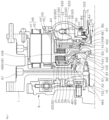
- the housing 1 has a first flow path A 1 that communicates with the second operation hole 461 . That is, as illustrated in FIG. 3 , the fluid to be supplied to the second operation chamber 25 is supplied to the second operation chamber 25 through the first flow path A 1 and the second operation hole 461 .
- a radial inner side of the first clutch pack 62 is connected to the rotor hub 43 .
- a lock-up input member 459 is provided at a radial inner side of the first clutch pack 62 , and the lock-up input member 459 is connected to the hub plate 45 of the rotor hub 43 .
- a support cylinder 633 is disposed rearward of the first piston plate 61 .
- a radial inner end of the support cylinder 633 is fixed to the hub plate 45 of the rotor hub 43 at a side positioned radially inward of the first clutch pack 62 . Further, a radial outer end of the first piston plate 61 slidably adjoins the support cylinder 633 .
- a first compensation hole 457 is formed in the hub plate 45 and disposed between the portion where the hub plate 45 is connected to the first guide cylinder 632 and the portion where the hub plate 45 adjoins the first piston plate 61 . Further, the first compensation hole 457 is formed such that the first compensation chamber 67 and the second accommodation space R 2 communicate with each other. Therefore, as illustrated in FIG. 2 , the fluid, which fills the second accommodation space R 2 through the second flow path A 2 , may be introduced into the first compensation chamber 67 .
- a first operation hole 458 is formed in the hub plate 45 and disposed between the portion where the hub plate 45 adjoins the first piston plate 61 and the portion where the hub plate 45 is connected to the support cylinder 633 .
- the first operation hole 458 is formed such that the first operation chamber 66 and the hollow portion of the output member 70 communicate with each other. Therefore, as illustrated in FIG. 4 , the transmission oil supplied through the third flow path A 3 may be introduced into the first operation chamber 66 through the first operation hole 458 .
- a space between the fixed end 75 and the output member 70 may define a fourth flow path A 4 for supplying the fluid from the transmission to the torque converter.
- the fluid when the fluid is supplied through the fourth flow path A 4 , the fluid may flow to the second space through the second circulation flow path hole 71 of the output member 70 and flow from the second space in a centrifugal direction.
- a part of the fluid which has flown to the second space through the second circulation flow path hole 71 , may flow to the first space through the first circulation flow path hole 451 and flow from the first space in the centrifugal direction.
- the pressure of the fluid stored in the first accommodation space R 1 is maintained as high pressure because of the characteristics of the torque converter.
- the pressure of the fluid stored in the first compensation chamber 67 just corresponds to the pressure of the fluid stored in the second accommodation space R 2 .
- the fluid stored in the second accommodation space R 2 has the pressure that generates a flow of fluid that cools or lubricates the bearings B 1 , B 2 , and B 3 and the second clutch pack 22 .
- the first surface of the first piston plate 61 faces the first compensation chamber 67 filled with the fluid with the pressure lower than the pressure of the fluid in the first accommodation space R 1 . Further, the second surface faces the first operation chamber 66 filled with the fluid with the pressure for moving the first piston plate 61 to the first clutch pack 62 .
- the present invention it is not necessary to configure a separate oil flow path or add a separate component to configure the first compensation chamber 67 and fill the first compensation chamber 67 with oil. Further, it is possible to fill the first compensation chamber 67 with the oil in the second accommodation space R 2 only by simply forming the first compensation hole 457 in the hub plate 45 that defines the boundary with the first compensation chamber 67 .
- the rotor hub 43 is connected to the first clutch pack 62 at the radial inner side of the first clutch pack 62
- the output member 70 is connected to the first clutch pack 62 at the radial outer side of the first clutch pack 62 .
- This may more simply configure the structures of and methods of assembling the first compensation chamber 67 , the first operation chamber 66 , and the first piston plate 61 in the structure according to the present invention in which the first piston plate 61 is disposed rearward of the first clutch pack 62 from the hub plate 45 .
Landscapes
- Engineering & Computer Science (AREA)
- Mechanical Engineering (AREA)
- Chemical & Material Sciences (AREA)
- Combustion & Propulsion (AREA)
- Transportation (AREA)
- General Engineering & Computer Science (AREA)
- Power Engineering (AREA)
- Hydraulic Clutches, Magnetic Clutches, Fluid Clutches, And Fluid Joints (AREA)
- Hybrid Electric Vehicles (AREA)
Abstract
Description
-
- 1: Housing
- 9: Spring damper (torsional damper)
- 10: Input member
- 102: Spline
- 104: First flow path hole
- 12: Input plate
- 122: Second flow path hole
- 20: Engine clutch
- 21: Second piston plate
- 22: Second clutch pack
- 24: Second compensation chamber
- 25: Second operation chamber
- 26: Second return spring
- 27: Second guide cylinder
- 40: Motor
- 41: Stator
- 42: Rotor
- 43: Rotor hub
- 44: Rotor holder
- 45: Hub plate
- 450: Central axis extension portion
- 452: Axial extension portion
- 451: First circulation flow path hole
- 457: First compensation hole
- 458: First operation hole
- 459: Lock-up input member
- 46: Hub ridge
- 460: Hub coupling portion
- 461: Second operation hole
- 462: Second compensation hole
- 464: Piston installation portion
- 50: Torque converter (fluid clutch)
- 51: Impeller
- 52: Back cover
- 522: Pump drive hub
- 54: Turbine
- 55: Turbine plate
- 56: Reactor
- 57: One-way clutch
- 60: Lock-up clutch
- 61: First piston plate
- 62: First clutch pack
- 632: First guide cylinder
- 633: Support cylinder
- 64: Lock-up output member
- 65: First return spring
- 66: First operation chamber
- 67: First compensation chamber
- 70: Output member
- 71: Second circulation flow path hole
- 75: Fixed end
- S1: Sealing member
- B1, B2, B3, B4, B5: Bearing
- A1: First flow path
- A2: Second flow path
- A3: Third flow path
- A4: Fourth flow path
- R1: First accommodation space
- R2: Second accommodation space
Claims (14)
Applications Claiming Priority (5)
| Application Number | Priority Date | Filing Date | Title |
|---|---|---|---|
| KR20200189835 | 2020-12-31 | ||
| KR10-2020-0189835 | 2020-12-31 | ||
| KR10-2021-0167615 | 2021-11-29 | ||
| KR1020210167615A KR102680620B1 (en) | 2020-12-31 | 2021-11-29 | Hybrid drive module |
| PCT/KR2021/020243 WO2022146065A1 (en) | 2020-12-31 | 2021-12-30 | Hybrid drive module |
Publications (2)
| Publication Number | Publication Date |
|---|---|
| US20240066972A1 US20240066972A1 (en) | 2024-02-29 |
| US12257904B2 true US12257904B2 (en) | 2025-03-25 |
Family
ID=82259530
Family Applications (1)
| Application Number | Title | Priority Date | Filing Date |
|---|---|---|---|
| US18/259,478 Active US12257904B2 (en) | 2020-12-31 | 2021-12-30 | Hybrid driving module |
Country Status (3)
| Country | Link |
|---|---|
| US (1) | US12257904B2 (en) |
| EP (1) | EP4230454B1 (en) |
| WO (1) | WO2022146065A1 (en) |
Families Citing this family (2)
| Publication number | Priority date | Publication date | Assignee | Title |
|---|---|---|---|---|
| KR102292260B1 (en) * | 2020-02-04 | 2021-08-20 | 주식회사 카펙발레오 | Hybrid drive module |
| DE102022201014A1 (en) * | 2022-02-01 | 2023-08-03 | Zf Friedrichshafen Ag | vehicle transmission |
Citations (15)
| Publication number | Priority date | Publication date | Assignee | Title |
|---|---|---|---|---|
| WO2004104439A1 (en) * | 2003-05-24 | 2004-12-02 | Dr. Ing. H.C. F. Porsche Aktiengesellschaft | Clutch device, in particular a multiplate clutch for a double-clutch gearbox |
| US20050133328A1 (en) | 2003-12-18 | 2005-06-23 | Fuji Jukogyo Kabushiki Kaisha | Torque converter |
| US20080072586A1 (en) | 2006-09-26 | 2008-03-27 | Hammond Matthew D | Drive unit for hybrid electric vehicle |
| CN101153635A (en) * | 2006-09-29 | 2008-04-02 | 本田技研工业株式会社 | dual clutch transmission |
| US20130056319A1 (en) | 2011-09-04 | 2013-03-07 | Schaeffler Technologies AG & Co. KG | Torque converter clutch with low back pressure |
| JP2013217452A (en) | 2012-04-10 | 2013-10-24 | Exedy Corp | Lock-up device for torque converter |
| US20160017971A1 (en) | 2014-07-16 | 2016-01-21 | Schaeffler Technologies AG & Co. KG | Torque converter clutch with reduced back pressure |
| EP2998603A1 (en) * | 2014-09-18 | 2016-03-23 | Valeo Embrayages | Dual wet clutch mechanism for a transmission system |
| US20180313409A1 (en) | 2017-04-27 | 2018-11-01 | Honda Motor Co., Ltd. | Hybrid vehicle drive apparatus |
| US20190309806A1 (en) * | 2018-04-10 | 2019-10-10 | Jtekt Corporation | Driving force distribution apparatus |
| US20200039496A1 (en) | 2018-08-02 | 2020-02-06 | Schaeffler Technologies AG & Co. KG | Hybrid module |
| KR20210029141A (en) | 2018-08-02 | 2021-03-15 | 섀플러 테크놀로지스 아게 운트 코. 카게 | Hybrid module configuration |
| US11121605B2 (en) | 2017-08-07 | 2021-09-14 | Schaeffler Technologies AG & Co. KG | Hybrid module with clutch balance chamber |
| US20220219524A1 (en) * | 2019-05-24 | 2022-07-14 | Exedy Globalparts Corporation | Integrated torque converter and p2 module |
| US20220242216A1 (en) * | 2019-09-27 | 2022-08-04 | Aisin Corporation | Vehicle drive device |
-
2021
- 2021-12-30 WO PCT/KR2021/020243 patent/WO2022146065A1/en not_active Ceased
- 2021-12-30 EP EP21915862.3A patent/EP4230454B1/en active Active
- 2021-12-30 US US18/259,478 patent/US12257904B2/en active Active
Patent Citations (23)
| Publication number | Priority date | Publication date | Assignee | Title |
|---|---|---|---|---|
| WO2004104439A1 (en) * | 2003-05-24 | 2004-12-02 | Dr. Ing. H.C. F. Porsche Aktiengesellschaft | Clutch device, in particular a multiplate clutch for a double-clutch gearbox |
| US20050133328A1 (en) | 2003-12-18 | 2005-06-23 | Fuji Jukogyo Kabushiki Kaisha | Torque converter |
| US20080072586A1 (en) | 2006-09-26 | 2008-03-27 | Hammond Matthew D | Drive unit for hybrid electric vehicle |
| CN101153635A (en) * | 2006-09-29 | 2008-04-02 | 本田技研工业株式会社 | dual clutch transmission |
| US9309956B2 (en) | 2011-09-04 | 2016-04-12 | Schaeffler Technologies AG & Co. KG | Torque converter clutch with low back pressure |
| US20130056319A1 (en) | 2011-09-04 | 2013-03-07 | Schaeffler Technologies AG & Co. KG | Torque converter clutch with low back pressure |
| US9494221B2 (en) | 2011-09-04 | 2016-11-15 | Schaeffler Technologies AG & Co. KG | Torque converter clutch with low back pressure |
| US20160178042A1 (en) | 2011-09-04 | 2016-06-23 | Schaeffler Technologies AG & Co. KG | Torque converter clutch with low back pressure |
| JP2013217452A (en) | 2012-04-10 | 2013-10-24 | Exedy Corp | Lock-up device for torque converter |
| US9303747B2 (en) | 2012-04-10 | 2016-04-05 | Exedy Corporation | Lock-up device for torque converter |
| US20150008086A1 (en) | 2012-04-10 | 2015-01-08 | Exedy Corporation | Lock-up device for torque converter |
| US20160017971A1 (en) | 2014-07-16 | 2016-01-21 | Schaeffler Technologies AG & Co. KG | Torque converter clutch with reduced back pressure |
| US9810302B2 (en) | 2014-07-16 | 2017-11-07 | Schaeffler Technologies AG & Co. KG | Torque converter clutch with reduced back pressure |
| EP2998603A1 (en) * | 2014-09-18 | 2016-03-23 | Valeo Embrayages | Dual wet clutch mechanism for a transmission system |
| JP2018184136A (en) | 2017-04-27 | 2018-11-22 | 本田技研工業株式会社 | Drive device for hybrid vehicle |
| US20180313409A1 (en) | 2017-04-27 | 2018-11-01 | Honda Motor Co., Ltd. | Hybrid vehicle drive apparatus |
| US10704614B2 (en) | 2017-04-27 | 2020-07-07 | Honda Motor Co., Ltd. | Hybrid vehicle drive apparatus |
| US11121605B2 (en) | 2017-08-07 | 2021-09-14 | Schaeffler Technologies AG & Co. KG | Hybrid module with clutch balance chamber |
| US20190309806A1 (en) * | 2018-04-10 | 2019-10-10 | Jtekt Corporation | Driving force distribution apparatus |
| US20200039496A1 (en) | 2018-08-02 | 2020-02-06 | Schaeffler Technologies AG & Co. KG | Hybrid module |
| KR20210029141A (en) | 2018-08-02 | 2021-03-15 | 섀플러 테크놀로지스 아게 운트 코. 카게 | Hybrid module configuration |
| US20220219524A1 (en) * | 2019-05-24 | 2022-07-14 | Exedy Globalparts Corporation | Integrated torque converter and p2 module |
| US20220242216A1 (en) * | 2019-09-27 | 2022-08-04 | Aisin Corporation | Vehicle drive device |
Non-Patent Citations (3)
| Title |
|---|
| Extended European Search Report issued Mar. 19, 2024, in corresponding European Patent Application No. 21915862.3 citing documents 1-3 therein, 7 pages. |
| International Search Report issued Apr. 11, 2022 in PCT/KR2021/020243 filed on Dec. 30, 2021 citing documents 1-11 & 15-17 therein 2 pages. |
| Office Action issued Jun. 25, 2024, in corresponding Korean Patent Application No. 10-2021-0167615, 6 pages. |
Also Published As
| Publication number | Publication date |
|---|---|
| US20240066972A1 (en) | 2024-02-29 |
| WO2022146065A1 (en) | 2022-07-07 |
| EP4230454A1 (en) | 2023-08-23 |
| EP4230454B1 (en) | 2025-04-16 |
| EP4230454A4 (en) | 2024-04-17 |
Similar Documents
| Publication | Publication Date | Title |
|---|---|---|
| US8757305B2 (en) | Hybrid drive arrangement | |
| US7114604B2 (en) | Torque converter | |
| US8836187B2 (en) | Vehicle drive device | |
| CN114787534B (en) | Hybrid drive module | |
| CN202228629U (en) | Hydraulic torque converter | |
| US12257904B2 (en) | Hybrid driving module | |
| US20140027231A1 (en) | Starting device | |
| US10637329B2 (en) | Hybrid motor assembly with rotor cooling and method thereof | |
| JP2007309516A (en) | Clutch structure | |
| CN115135523A (en) | Hybrid module including a torque converter inside an electric motor and having a distal compensation chamber | |
| EP4606611A1 (en) | Hybrid driving module | |
| US20240408954A1 (en) | Hybrid drive module | |
| KR102876353B1 (en) | Hybrid drive module | |
| KR102680620B1 (en) | Hybrid drive module | |
| JPH10159902A (en) | Friction facing and lockup clutch using it | |
| US12494690B2 (en) | Hybrid driving module | |
| US7980370B2 (en) | Lockup device and hydraulic torque transmission device provided with the same | |
| JPH10148249A (en) | Torque converter | |
| JP4303406B2 (en) | Fluid coupling | |
| US6286648B1 (en) | Lockup device of a torque converter | |
| US11331998B2 (en) | System for a hybrid torque converter with e-motor on an output | |
| KR20220097286A (en) | Hybrid drive module | |
| KR102616855B1 (en) | Hybrid drive module | |
| CN116457230A (en) | Hybrid power driving module | |
| CN119489676A (en) | Hybrid Transmission Module |
Legal Events
| Date | Code | Title | Description |
|---|---|---|---|
| AS | Assignment |
Owner name: VALEO KAPEC CO., LTD., KOREA, REPUBLIC OF Free format text: ASSIGNMENT OF ASSIGNORS INTEREST;ASSIGNOR:KIM, JUNG-WOO;REEL/FRAME:064082/0241 Effective date: 20230522 |
|
| FEPP | Fee payment procedure |
Free format text: ENTITY STATUS SET TO UNDISCOUNTED (ORIGINAL EVENT CODE: BIG.); ENTITY STATUS OF PATENT OWNER: LARGE ENTITY |
|
| STPP | Information on status: patent application and granting procedure in general |
Free format text: DOCKETED NEW CASE - READY FOR EXAMINATION |
|
| STPP | Information on status: patent application and granting procedure in general |
Free format text: NON FINAL ACTION MAILED |
|
| STPP | Information on status: patent application and granting procedure in general |
Free format text: RESPONSE TO NON-FINAL OFFICE ACTION ENTERED AND FORWARDED TO EXAMINER |
|
| STPP | Information on status: patent application and granting procedure in general |
Free format text: NOTICE OF ALLOWANCE MAILED -- APPLICATION RECEIVED IN OFFICE OF PUBLICATIONS |
|
| STPP | Information on status: patent application and granting procedure in general |
Free format text: PUBLICATIONS -- ISSUE FEE PAYMENT RECEIVED |
|
| STPP | Information on status: patent application and granting procedure in general |
Free format text: PUBLICATIONS -- ISSUE FEE PAYMENT VERIFIED |
|
| STCF | Information on status: patent grant |
Free format text: PATENTED CASE |