US12257079B2 - Intraocular pressure sensor - Google Patents
Intraocular pressure sensor Download PDFInfo
- Publication number
- US12257079B2 US12257079B2 US17/971,060 US202217971060A US12257079B2 US 12257079 B2 US12257079 B2 US 12257079B2 US 202217971060 A US202217971060 A US 202217971060A US 12257079 B2 US12257079 B2 US 12257079B2
- Authority
- US
- United States
- Prior art keywords
- film component
- iop
- reflective film
- iop sensor
- resonance chamber
- Prior art date
- Legal status (The legal status is an assumption and is not a legal conclusion. Google has not performed a legal analysis and makes no representation as to the accuracy of the status listed.)
- Active, expires
Links
Images


Classifications
-
- A—HUMAN NECESSITIES
- A61—MEDICAL OR VETERINARY SCIENCE; HYGIENE
- A61B—DIAGNOSIS; SURGERY; IDENTIFICATION
- A61B5/00—Measuring for diagnostic purposes; Identification of persons
- A61B5/68—Arrangements of detecting, measuring or recording means, e.g. sensors, in relation to patient
- A61B5/6846—Arrangements of detecting, measuring or recording means, e.g. sensors, in relation to patient specially adapted to be brought in contact with an internal body part, i.e. invasive
- A61B5/6847—Arrangements of detecting, measuring or recording means, e.g. sensors, in relation to patient specially adapted to be brought in contact with an internal body part, i.e. invasive mounted on an invasive device
-
- A—HUMAN NECESSITIES
- A61—MEDICAL OR VETERINARY SCIENCE; HYGIENE
- A61B—DIAGNOSIS; SURGERY; IDENTIFICATION
- A61B3/00—Apparatus for testing the eyes; Instruments for examining the eyes
- A61B3/10—Objective types, i.e. instruments for examining the eyes independent of the patients' perceptions or reactions
- A61B3/16—Objective types, i.e. instruments for examining the eyes independent of the patients' perceptions or reactions for measuring intraocular pressure, e.g. tonometers
-
- A—HUMAN NECESSITIES
- A61—MEDICAL OR VETERINARY SCIENCE; HYGIENE
- A61B—DIAGNOSIS; SURGERY; IDENTIFICATION
- A61B2562/00—Details of sensors; Constructional details of sensor housings or probes; Accessories for sensors
- A61B2562/16—Details of sensor housings or probes; Details of structural supports for sensors
- A61B2562/168—Fluid filled sensor housings
Definitions
- the present disclosure relates to the technical field of medical devices, in particular to an intraocular pressure (IOP) sensor.
- IOP intraocular pressure
- Intraocular pressure is always an important indicator for glaucoma condition, which is of vital importance to the diagnosis and postoperative observation by doctors.
- the measurement of IOP is mainly indirect measurement, which is used to measure corneal deformation mainly by utilizing various sensing principles, such as Imbert-Fick principle, electromagnetic induction probe rebound principle and PASCAL principle and then obtain the value of IOP by utilizing the relationship between corneal deformation and IOP.
- various sensing principles such as Imbert-Fick principle, electromagnetic induction probe rebound principle and PASCAL principle
- GAT Goldmann applanation tonometer
- ICare rebound tonometer is a popular handheld tonometer in the market, which is newly developed based on the theory of inductive rebound proposed by Antti Kontiola.
- RBT ICare rebound tonometer
- NCT is one of the most widely used tonometers in clinical practice in China, which, together with GAT, falls into the scope of applanation tonometers.
- NCT is suitable for large-scale census and outpatient owing to simple operation, good repeatability for repeated measurements and easy acceptance by patients.
- IOP in patients with high astigmatism, corneal opacity and poor fixation, and patients having received corneal transplantation.
- studies have shown that the stability of NCT in the measurement of high IOP area is low, and since NCT is a large bench device, patients can only be measured in sitting position. Therefore, NCT is not suitable for patients with mobility difficulties and elderly patients.
- Triggerfish CLS is a contact-type IOP sensor.
- IOP of human When IOP of human is changed, the corneal curvature will be changed, which is the physiological characteristic of human eye serving as the basis for the design of Triggerfish CLS.
- the biggest advantage of Triggerfish CLS is non-invasive continuous monitoring for simple, fast and convenient operation. However, it also has the significant disadvantage that it can only provide the relative change of IOP but not the absolute IOP, which causes inconvenience for the diagnosis of doctors.
- Triggerfish CLS has a certain impact on the field of view when being worn for the presence of built-in induction coil, chip, etc.
- the present disclosure provides an IOP sensor intended to be implanted into the anterior chamber of eyes for continuous detection of IOP, with direct measurement method and high measurement accuracy, which solves the problem that tonometers in the prior art can be only used for single measurement, and improves the accuracy of measurement results.
- the IOP sensor includes a transmission film component, which is in direct contact with intraocular aqueous humor and configured to sense pressure fluctuations in the intraocular aqueous humor; a reflective film component set on an inner side of the transmission film component; and an adhesion layer component set on an inner layer of the reflective film component and configured to connect to an attachment device.
- An enclosed space formed by the reflective film component and the transmission film component constitutes a resonance chamber, which is filled with a filling medium.
- the transmission film component When a pressure in the intraocular aqueous humor is changed, the transmission film component is deformed, resulting in a change in a near-infrared (NIR) spectrum reflected by the reflective film component; the IOP is detected according to the change of the NIR spectrum.
- NIR near-infrared
- the transmission film component, the reflective film component and the adhesion layer component are made of light curing materials.
- the outer surface of the transmission film component has a surface plasmon structure.
- the surface plasmon structure is a lattice or boss structure.
- the reflective film component is provided with a total reflection structure.
- the total reflection structure is in pyramid array.
- the reflective film component is made of the material with high refractive index greater than 1.5.
- the material with high refractive index is doped with inorganic nanoparticles.
- the inorganic nanoparticles are selected from at least one of Ge, Bi, SiN and SiO 2 .
- the filling medium is liquid or gas.
- the liquid is selected from any one of uncured light curing material (i.e., a light curing material that has not been cured) or glycerin;
- the gas is selected from any one of air, oxygen and inert gas.
- the adhesion layer component when the filling medium is not made of the uncured light curing material, the adhesion layer component is provided with a blocked drainage hole.
- the IOP sensor provided by the present disclosure is simple in structure and convenient in operation, and has the ability of continuous non-invasive detection of IOP.
- the sensor is intended to be implanted into the anterior chamber of patients' eyes to directly measure the pressure of anterior aqueous humor by utilizing the principle of multibeam interference according to the change in pressure difference between the aqueous humor and the filling medium, which, on the one hand, reflects the real IOP of patients and improves the accuracy of measurement results, and on the other hand, enables patients to conduct self-detection at any time without the operation of doctors and solves the problem that tonometers in the prior art can be only used for single measurement, thus improving the comprehensive performance of the IOP sensor.
- FIG. 1 is the structural diagram I of the IOP sensor in the present disclosure
- FIG. 2 is the size diagram I of the IOP sensor in Embodiment 1 of the present disclosure
- FIG. 3 is the size diagram II of the IOP sensor in Embodiment 1 of the present disclosure.
- FIG. 4 is the structural diagram II of the IOP sensor in the present disclosure.
- FIG. 5 is the size diagram of the IOP sensor in Embodiment 2 of the present disclosure.
- FIG. 6 is the detection process diagram of the IOP sensor in the present disclosure.
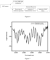
- FIG. 7 is the detection spectrum obtained in the detection example of the present disclosure.
- FIG. 8 is the characteristic wave of the detection spectrum in the detection example of the present disclosure.
- FIG. 9 is the characteristic spectrum of the detection spectrum in the detection example of the present disclosure.
- FIG. 10 illustrates structural diagrams of an IOP sensor containing a drainage hole in accordance with an embodiment of the present disclosure, including a front view, a side view, and a perspective view of the IOP sensor.
- the IOP sensor includes: a transmission film component 102 , which is in direct contact with intraocular aqueous humor for sensing the pressure fluctuations of the intraocular aqueous humor and has a transmission film body on which a cladding layer can be arranged to increase transmissivity; a reflective film component 104 , which is set on the inner side of the transmission film component 102 and has a reflective film body of either a printed layer mirror with strong reflectivity or a flat mirror with zero curvature corresponding to the shape of the transmission film component 102 ; and an adhesion layer component 106 , which is set on the inner layer of the reflective film component 104 configured to connect to an attachment device that can be a medical device that performs a specific function, such as a drainage tube for the treatment of glaucoma.
- the enclosed space formed by the reflective film component 102 which is in direct contact with intraocular aqueous humor for sensing the pressure fluctuations of the intraocular aqueous humor and has a transmission film body on which a cla
- the IOP sensor can be implanted into the anterior chamber of the patient's eye to make the transmission film component 102 come into contact with the aqueous humor in the eye, so that the intraocular aqueous humor and the filling medium are located on both sides of the transmission film component 102 .
- the pressure difference between the filling medium in the resonance chamber 110 and the aqueous humor in the eye will also be changed due to the constant pressure of the filling medium in the chamber, which causes deformation of the transmission film component 102 , thus resulting in the change of the thickness of the resonance chamber 110 , that is, the distance between the transmission film component 102 and the reflective film component 104 and the change of reflection spectrum.
- the deformation of the transmission film component results in the change of the NIR spectrum as reflected by the reflective film component 104 .
- the external receiver receives the reflection spectrum to analyze the characteristic wave and IOP value for the purpose of the detection of IOP according to the change of the NIR spectrum.
- the preferred wavelength range of the NIR light is 800 nm to 2000 nm for the present disclosure.
- the transmission film component 102 constitutes the external profile of the IOP sensor, and the transmission film component 102 , reflective film component 104 and adhesion layer component 106 are all of annular structure.
- the adhesion layer component 106 has an internal columnar cavity 108 . The specific structure and size can be set according to demand.
- the IOP sensor provided by the present disclosure is simple in structure and convenient in operation, and has the ability of continuous non-invasive detection of IOP.
- the sensor is intended to be implanted into the anterior chamber of the patient's eye to directly measure the pressure of anterior aqueous humor by utilizing the principle of multibeam interference according to the change in pressure difference between aqueous humor and a filling medium, which, on the one hand, reflects the real IOP of patients and improves the accuracy of measurement results, and on the other hand, enables patients to conduct self-detection at any time without the operation of doctors and solves the problem that tonometers in the prior art can be only used for single measurement, thus improving the comprehensive performance of the IOP sensor.
- the existing Triggerfish CLS can also be used for continuous monitoring of IOP, it cannot be implanted and may affect patients' field of view when being worn.
- the IOP sensor is used for measuring IOP according to the change of corneal curvature with the change of the IOP, which cannot be used for direct measurement of IOP, with low accuracy of measurement results.
- the IOP sensor provided by the present disclosure can be used not only for continuous measurement but also for direct measurement of IOP, which improves the accuracy of measurement results, thereby improving the comprehensive performance of the IOP sensor.
- the IOP sensor provided by the present disclosure can be manufactured by such methods as light curing micro-nano printing, gas phase precipitation, mold forming, and two-photon printing, which is preferred for integrated printing molding for the present disclosure.
- the transmission film component 102 , the reflective film component 104 and the adhesion layer component 106 are preferably made of light curing material, which can be any light curing material in the prior art suitable for implantation in the patient's eye, such as the material made by curing with light-cured resin, the material made by curing with light-cured resin and monomer, or the material made by curing with various light-cured resins.
- the external surface of the preferred transmission film component 102 is of surface plasmon structure for the present disclosure to increase the amplitude of reflected light.
- the surface plasmon structure is a lattice or boss structure which can be nano-gold lattice formed by gold printing.
- the diameter range of each dot in the lattice structure preferred for the present disclosure is 300 nm to 800 nm, and the lattice range corresponds to the position of the reflective film component 104 .
- the reflective film component 104 preferred for the present disclosure is designed with a total reflection structure to enhance the reflection ability, so as to improve the sensitivity of detection.
- the total reflection structure preferred for the present disclosure is in pyramid array.
- the refractive index of the reflective film component 104 can also be increased by choosing a material with high refractive index for it, so as to improve the sensitivity of detection.
- the material with high refractive index for the present disclosure refers to the material whose refractive index is greater than 1.5.
- the material doped with inorganic nanoparticles is preferred for the reflective film component 104 in the present disclosure, and the material doped with inorganic nanoparticles with high refractive index is more preferred.
- the inorganic nanoparticles can be selected from at least one of Ge, Bi, SiN and SiO 2 .
- the filling medium in the resonance chamber 110 in the present disclosure can be any liquid or gas that can exist stably in the resonance chamber 110 for the convenience of measuring the change of aqueous humor pressure in the eye.
- the liquid When the filling medium is a liquid, the liquid may be selected from either an uncured light-curing material or glycerol; when the filling medium is a gas, the gas can be selected from any one of the air, oxygen and inert gas.
- the uncured light-curing material can be an uncured light-curing material for printing the overall structure of the IOP sensor, that is, a printed material.
- a certain amount of printing material may be retained in the resonance chamber 110 in the printing process of the IOP sensor.
- the printing material is the uncured light curing material, which can directly serve as the filling medium.
- a fluid other than the printing material such as glycerin, air or inert gas
- a drainage hole for example, drainage hole 210 as shown in FIG. 10
- the diameter range of the drainage hole preferred for the present disclosure is 10 ⁇ m to 50 ⁇ m.
- the drainage hole can be blocked by making a cylinder matching the inner cavity of the adhesion layer component 106 and externally painted with a photosensitive adhesive to be inserted into the inner cavity 108 of the adhesion layer component 106 and fitted closely with the inner cavity 108 of the adhesion layer component 106 by aid of light.
- the cylinder inserted into the adhesion layer component 106 can be extended axially beyond the IOP sensor, while the extended part can be secured on the tissue.
- the overall structure of the IOP sensor in the present disclosure can be of prism, cylinder and other geometric structure.
- One structure for the IOP sensor is as follows: the front segment 208 is cylindrical, with a diameter of 250 ⁇ m to 500 ⁇ m, a wall thickness of 50 ⁇ m to 100 ⁇ m, and a length of 250 ⁇ m to 1000 ⁇ m; the middle segment 204 is polyhedral or cylindrical, with the envelope of polyhedral edge 206 located in the external profile of the front segment 208 and spaced 2 ⁇ m to 20 ⁇ m apart; the end segment 202 is of round table structure with a certain gradient, whose large end is in contact with the middle segment 204 , with a wall thickness of 50 ⁇ m to 100 ⁇ m, a height of 250 ⁇ m to 1000 ⁇ m, and a slope of 5° to 30°; the reflective film component 104 is polygonal with single feature or of a closed structure formed by feature polygons.
- Another structure for the IOP sensor is as follows: The IOP
- the IOP sensor provided by the present disclosure is small in size and can be implanted into the eye through minimally invasive surgery with little damage to human body.
- EYEMATE is an implantable IOP sensor for in situ measurement.
- the sensor is equipped with a special integrated chip (MEMS-ASIC) and integrated with an antenna, an induction coil, etc., which can directly sense IOP through the pressure sensor and wirelessly transmit the IOP data.
- MEMS-ASIC mobile electronic circuitry
- the sensor power supply powers the sensor under the principle of magnetic induction.
- the encapsulated EYEMATE has an inner diameter of 7 mm and outer diameters of 11.3 mm, 11.7 mm and 12.1 mm.
- ASIC has a thickness of 0.9 mm, or otherwise 0.5 mm around the microcoil. Its surface is in lenticular round shape for smoothly accommodating the curved sclera shape.
- the second-generation EYEMATE is structurally improved compared with the first-generation EYEMATE, with the size of 7.5 ⁇ 3.3 mm, the peripheral thickness of 0.9 mm, and the central thickness of 2.2 mm. Due to its large size, EYEMATE needs to be surgically implanted, which brings a certain risk of infection and inconvenience for replacement and maintenance if it's damaged.
- the IOP sensor provided by the present disclosure is reduced in size by 1 to 2 orders of magnitude, which can be implanted into the eye by minimally invasive method to reduce the harm to human body.
- the IOP sensor provided by the present disclosure can also be connected with a drainage device with the function of drainage of aqueous humor through the attachment device to make the IOP sensor highly scalable.
- the embodiment provides an IOP sensor suitable for minimally invasive implantation into the anterior chamber of the patient's eye, as shown in FIG. 1 .
- the IOP sensor has an overall shape of square column and internal shape of column. As shown in FIGS. 2 and 3 , the IOP sensor has an appearance size of 0.2 ⁇ 0.2 ⁇ 0.31 mm, with the height of 0.31 mm composed of 0.005 mm for upper and lower parts of the resonance cavity cover respectively and 0.3 mm for the intermediate part of the effective detection region.
- the IOP sensor has an inner round cavity diameter of 0.15 mm, which is also the diameter of the inner cavity of the adhesion layer component 106 , whose size mainly depends on the size of the attachment device and can be adjusted as appropriate according to it.
- the IOP sensor has a film thickness of 0.002 mm, which is also the thickness of the transmission film component 102 .
- the resonance chamber 110 has an inner cavity thickness of 0.015 mm, and the reflective film component 104 has a thickness of 0.008 mm.
- the transmission film component 102 , the resonance chamber 110 and the reflective film component 104 have an overall thickness of 0.025 mm.
- the cover has a thickness of 0.023 mm.
- the IOP sensor in the embodiment is printed integrally by two-photon printing technology, and the filling medium in the resonance chamber 110 is printing material, with no need for drainage hole.
- the embodiment provides an IOP sensor suitable for minimally invasive implantation into the anterior chamber of the patient's eye, as shown in FIG. 4 .
- the TOP sensor has an overall appearance of cylinder, with an internal structure of round cylinder.
- the IOP sensor has an overall height of 1.25 mm, an outer diameter of 0.3 mm and an inner diameter of 0.22 mm.
- the transmission film component 102 has a thickness of 0.002 mm, and the resonance chamber 110 has a thickness of 0.007 mm.
- the adhesion layer component 106 is provided with a drainage hole connected with the resonance chamber 110 .
- the IOP sensor provided in Embodiment 1 is used for detection according to the detection method shown in FIG. 6 .
- the detection spectrum shown in FIG. 7 contains the comprehensive spectrum of the resonance cavity thickness.
- the amount of characteristic waves is analyzed by fast Fourier transform to obtain the spectrum as shown in FIG. 8 .
- the detection spectrum is subject to filtering processing according to analyzed characteristic waves to obtain the characteristic spectrum as shown in FIG. 9 .
- the thickness of the resonance chamber 110 is calculated according to the characteristic spectrum, and the IOP is further calculated according to the thickness.
- fsr is the distance between two troughs
- ⁇ is the mean wavelength between two troughs
- n is the refractive index of the filling medium
- L is the thickness of the resonance cavity.
- the characteristic cavity thickness of the resonance cavity is calculated according to the spectral analysis results in FIG. 9 .
- the transmission film component 102 is deformed to a certain degree, while the aqueous humor pressure changes proportionally with the decrease of the cavity thickness.
- the patient's intraocular aqueous humor pressure (namely IOP) is obtained.
Landscapes
- Life Sciences & Earth Sciences (AREA)
- Health & Medical Sciences (AREA)
- General Health & Medical Sciences (AREA)
- Molecular Biology (AREA)
- Veterinary Medicine (AREA)
- Engineering & Computer Science (AREA)
- Biomedical Technology (AREA)
- Heart & Thoracic Surgery (AREA)
- Medical Informatics (AREA)
- Biophysics (AREA)
- Surgery (AREA)
- Animal Behavior & Ethology (AREA)
- Physics & Mathematics (AREA)
- Public Health (AREA)
- Ophthalmology & Optometry (AREA)
- Pathology (AREA)
- Eye Examination Apparatus (AREA)
Abstract
Description
Claims (12)
Applications Claiming Priority (2)
| Application Number | Priority Date | Filing Date | Title |
|---|---|---|---|
| CN202210432869.8 | 2022-04-24 | ||
| CN202210432869.8A CN114569063B (en) | 2022-04-24 | 2022-04-24 | Intraocular pressure sensor |
Publications (2)
| Publication Number | Publication Date |
|---|---|
| US20230337983A1 US20230337983A1 (en) | 2023-10-26 |
| US12257079B2 true US12257079B2 (en) | 2025-03-25 |
Family
ID=81784124
Family Applications (1)
| Application Number | Title | Priority Date | Filing Date |
|---|---|---|---|
| US17/971,060 Active 2042-10-30 US12257079B2 (en) | 2022-04-24 | 2022-10-21 | Intraocular pressure sensor |
Country Status (2)
| Country | Link |
|---|---|
| US (1) | US12257079B2 (en) |
| CN (1) | CN114569063B (en) |
Families Citing this family (1)
| Publication number | Priority date | Publication date | Assignee | Title |
|---|---|---|---|---|
| CN116965771B (en) * | 2023-06-25 | 2024-10-18 | 明澈生物科技(苏州)有限公司 | Optical microscopic system for intraocular pressure measurement |
Citations (19)
| Publication number | Priority date | Publication date | Assignee | Title |
|---|---|---|---|---|
| US5343861A (en) * | 1989-04-10 | 1994-09-06 | Herman Wesley K | Disposable tonometer cover with fluorescein dye |
| US20040254438A1 (en) | 2003-01-09 | 2004-12-16 | The Regents Of The University Of California | Implantable devices and methods for measuring intraocular, subconjunctival or subdermal pressure and/or analyte concentration |
| WO2012137067A2 (en) | 2011-04-07 | 2012-10-11 | Oculox Technology | Intraocular pressure monitoring device and methods |
| US20120302861A1 (en) | 2011-04-27 | 2012-11-29 | Istar Medical | Device and method for glaucoma management and treatment |
| WO2013059195A1 (en) | 2011-10-17 | 2013-04-25 | Elenza, Inc. | Methods, apparatus, and system for triggering an accommodative implantable ophthalmic device based on changes in intraocular pressure |
| US20130150777A1 (en) * | 2011-12-12 | 2013-06-13 | Sebastian Böhm | Glaucoma Drainage Devices Including Vario-Stable Valves and Associated Systems and Methods |
| US20160007851A1 (en) * | 2013-03-07 | 2016-01-14 | The Board Of Trustees Of The Leland Stanford Junior University | Implantable Pressure Sensors for Telemetric Measurements through Bodily Tissues |
| US20170127941A1 (en) | 2014-06-27 | 2017-05-11 | Implandata Ophthalmic Products Gmbh | Implant for determining intraocular pressure |
| US20170209045A1 (en) | 2016-01-26 | 2017-07-27 | California Institute Of Technology | System and method for intraocular pressure sensing |
| WO2017137911A1 (en) | 2016-02-12 | 2017-08-17 | VALTRIANI, Massimiliano | Intraocular lens comprising a tonometer |
| US20170251921A1 (en) * | 2014-10-20 | 2017-09-07 | The Regents Of The University Of California | Optical intraocular sensor and sensing method |
| CN107432733A (en) | 2016-05-27 | 2017-12-05 | 深圳硅基传感科技有限公司 | Implanted intraocular pressure monitor |
| WO2018090330A1 (en) * | 2016-11-18 | 2018-05-24 | 深圳先进技术研究院 | Implantable device and preparation method therefor |
| CN108634929A (en) | 2018-05-16 | 2018-10-12 | 沈阳工业大学 | A kind of continuous Monitoring and control system of implanted intraocular pressure |
| US20190380578A1 (en) * | 2018-06-17 | 2019-12-19 | John Naber | Ocular System and Method |
| US10687704B2 (en) | 2009-12-30 | 2020-06-23 | The University Of Kentucky Research Foundation | System, device, and method for determination of intraocular pressure |
| WO2020210322A1 (en) * | 2019-04-10 | 2020-10-15 | Smartlens, Inc. | Intraocular pressure monitoring devices and methods of using the same |
| WO2020232015A1 (en) * | 2019-05-13 | 2020-11-19 | Verily Life Sciences Llc | Systems, devices and methods for optical interrogation of an implantable intraocular pressure sensor |
| US20210353145A1 (en) * | 2020-05-15 | 2021-11-18 | Icahn School Of Medicine At Mount Sinai | Methods, devices, and systems for monitoring intraocular pressure |
-
2022
- 2022-04-24 CN CN202210432869.8A patent/CN114569063B/en active Active
- 2022-10-21 US US17/971,060 patent/US12257079B2/en active Active
Patent Citations (20)
| Publication number | Priority date | Publication date | Assignee | Title |
|---|---|---|---|---|
| US5343861A (en) * | 1989-04-10 | 1994-09-06 | Herman Wesley K | Disposable tonometer cover with fluorescein dye |
| US20040254438A1 (en) | 2003-01-09 | 2004-12-16 | The Regents Of The University Of California | Implantable devices and methods for measuring intraocular, subconjunctival or subdermal pressure and/or analyte concentration |
| US10687704B2 (en) | 2009-12-30 | 2020-06-23 | The University Of Kentucky Research Foundation | System, device, and method for determination of intraocular pressure |
| WO2012137067A2 (en) | 2011-04-07 | 2012-10-11 | Oculox Technology | Intraocular pressure monitoring device and methods |
| US20120302861A1 (en) | 2011-04-27 | 2012-11-29 | Istar Medical | Device and method for glaucoma management and treatment |
| WO2013059195A1 (en) | 2011-10-17 | 2013-04-25 | Elenza, Inc. | Methods, apparatus, and system for triggering an accommodative implantable ophthalmic device based on changes in intraocular pressure |
| US20130150777A1 (en) * | 2011-12-12 | 2013-06-13 | Sebastian Böhm | Glaucoma Drainage Devices Including Vario-Stable Valves and Associated Systems and Methods |
| US20160007851A1 (en) * | 2013-03-07 | 2016-01-14 | The Board Of Trustees Of The Leland Stanford Junior University | Implantable Pressure Sensors for Telemetric Measurements through Bodily Tissues |
| US20170127941A1 (en) | 2014-06-27 | 2017-05-11 | Implandata Ophthalmic Products Gmbh | Implant for determining intraocular pressure |
| US20170251921A1 (en) * | 2014-10-20 | 2017-09-07 | The Regents Of The University Of California | Optical intraocular sensor and sensing method |
| US20170209045A1 (en) | 2016-01-26 | 2017-07-27 | California Institute Of Technology | System and method for intraocular pressure sensing |
| WO2017137911A1 (en) | 2016-02-12 | 2017-08-17 | VALTRIANI, Massimiliano | Intraocular lens comprising a tonometer |
| CN107432733A (en) | 2016-05-27 | 2017-12-05 | 深圳硅基传感科技有限公司 | Implanted intraocular pressure monitor |
| WO2018090330A1 (en) * | 2016-11-18 | 2018-05-24 | 深圳先进技术研究院 | Implantable device and preparation method therefor |
| CN108634929A (en) | 2018-05-16 | 2018-10-12 | 沈阳工业大学 | A kind of continuous Monitoring and control system of implanted intraocular pressure |
| US20190380578A1 (en) * | 2018-06-17 | 2019-12-19 | John Naber | Ocular System and Method |
| WO2020210322A1 (en) * | 2019-04-10 | 2020-10-15 | Smartlens, Inc. | Intraocular pressure monitoring devices and methods of using the same |
| WO2020232015A1 (en) * | 2019-05-13 | 2020-11-19 | Verily Life Sciences Llc | Systems, devices and methods for optical interrogation of an implantable intraocular pressure sensor |
| CN113795188A (en) | 2019-05-13 | 2021-12-14 | 二十-二十治疗有限责任公司 | Systems, devices and methods for optical interrogation of implantable intraocular pressure sensors |
| US20210353145A1 (en) * | 2020-05-15 | 2021-11-18 | Icahn School Of Medicine At Mount Sinai | Methods, devices, and systems for monitoring intraocular pressure |
Also Published As
| Publication number | Publication date |
|---|---|
| US20230337983A1 (en) | 2023-10-26 |
| CN114569063B (en) | 2022-08-19 |
| CN114569063A (en) | 2022-06-03 |
Similar Documents
| Publication | Publication Date | Title |
|---|---|---|
| KR100411363B1 (en) | A tonometer system for measuring intraocular pressure by applanation and/or indentation | |
| US20170209045A1 (en) | System and method for intraocular pressure sensing | |
| JPH09509334A (en) | Device for monitoring intraocular pressure and blood pressure | |
| Piso et al. | Modern monitoring intraocular pressure sensing devices based on application specific integrated circuits | |
| US12257079B2 (en) | Intraocular pressure sensor | |
| Nuyen et al. | Detecting IOP fluctuations in glaucoma patients | |
| Eklund et al. | An applanation resonator sensor for measuring intraocular pressure using combined continuous force and area measurement | |
| CN116269200A (en) | A continuous intraocular pressure monitoring sensor and intraocular pressure measurement method | |
| Xu et al. | Recent progress of continuous intraocular pressure monitoring | |
| AU2014353861B2 (en) | Device for determining an intraocular pressure of an eye | |
| CN112190229A (en) | Intraocular pressure monitoring device for external rigid-internal soft double-layer corneal contact lens | |
| CN112450877A (en) | Intelligent contact lens with full-cornea fiber grating sensors arranged in series | |
| Kanngiesser et al. | Simulation of dynamic contour tonometry compared to in vitro study revealing minimal influence of corneal radius and astigmatism. The theoretical foundations of dynamic contour tonometry | |
| WO2017167670A1 (en) | A contact lens, a system and a method of measuring a physiological characteristic of an eye of a subject | |
| Yolcu et al. | Conventional intraocular pressure measurement techniques | |
| Brusini et al. | Intraocular pressure and its measurement | |
| AU758525B2 (en) | A tonometer system for measuring intraocular pressure by applanation and/or indentation | |
| US20230111664A1 (en) | Hand-held radar system to measure intraocular pressure and to assess eye diseases and method therefor | |
| CN223284015U (en) | High-frequency ultrasonic indentation device for in vitro measurement of corneal biomechanical properties | |
| US20240382091A1 (en) | System for measurement of an intraocular implant | |
| CN121421444A (en) | Scleral endoscope device, monitoring method and system for non-invasive monitoring of aqueous humor outflow coefficient | |
| MXPA99002157A (en) | A tonometer system for measuring intraocular pressure by applanation and/or indentation | |
| Guozhen | Development of Contact Lens Sensor and Wireless Sensing System for Intraocular Pressure Monitoring | |
| Amigo | The Maklakoff applanation tonometer | |
| Schneider et al. | Dynamic contour tonometry |
Legal Events
| Date | Code | Title | Description |
|---|---|---|---|
| AS | Assignment |
Owner name: MINGCHE BIOTECHNOLOGY CO., LTD, CHINA Free format text: ASSIGNMENT OF ASSIGNORS INTEREST;ASSIGNORS:REN, DONGNI;WANG, FULE;WANG, KEMIN;AND OTHERS;REEL/FRAME:061499/0752 Effective date: 20220926 |
|
| FEPP | Fee payment procedure |
Free format text: ENTITY STATUS SET TO UNDISCOUNTED (ORIGINAL EVENT CODE: BIG.); ENTITY STATUS OF PATENT OWNER: MICROENTITY |
|
| FEPP | Fee payment procedure |
Free format text: ENTITY STATUS SET TO MICRO (ORIGINAL EVENT CODE: MICR); ENTITY STATUS OF PATENT OWNER: MICROENTITY |
|
| STPP | Information on status: patent application and granting procedure in general |
Free format text: FINAL REJECTION MAILED |
|
| STPP | Information on status: patent application and granting procedure in general |
Free format text: ADVISORY ACTION MAILED |
|
| STPP | Information on status: patent application and granting procedure in general |
Free format text: DOCKETED NEW CASE - READY FOR EXAMINATION |
|
| STPP | Information on status: patent application and granting procedure in general |
Free format text: NON FINAL ACTION MAILED |
|
| STPP | Information on status: patent application and granting procedure in general |
Free format text: NOTICE OF ALLOWANCE MAILED -- APPLICATION RECEIVED IN OFFICE OF PUBLICATIONS |
|
| STPP | Information on status: patent application and granting procedure in general |
Free format text: PUBLICATIONS -- ISSUE FEE PAYMENT VERIFIED |
|
| STCF | Information on status: patent grant |
Free format text: PATENTED CASE |