US12255032B2 - Maintenance-free gas density relay and cross-checking method therefor - Google Patents
Maintenance-free gas density relay and cross-checking method therefor Download PDFInfo
- Publication number
- US12255032B2 US12255032B2 US17/640,773 US202017640773A US12255032B2 US 12255032 B2 US12255032 B2 US 12255032B2 US 202017640773 A US202017640773 A US 202017640773A US 12255032 B2 US12255032 B2 US 12255032B2
- Authority
- US
- United States
- Prior art keywords
- gas density
- value
- pressure
- temperature
- gas
- Prior art date
- Legal status (The legal status is an assumption and is not a legal conclusion. Google has not performed a legal analysis and makes no representation as to the accuracy of the status listed.)
- Active, expires
Links
- 238000000034 method Methods 0.000 title claims abstract description 38
- 238000001514 detection method Methods 0.000 claims abstract description 187
- 238000012544 monitoring process Methods 0.000 claims abstract description 123
- 238000004891 communication Methods 0.000 claims abstract description 49
- 238000012423 maintenance Methods 0.000 claims abstract description 38
- 230000001105 regulatory effect Effects 0.000 claims description 82
- 230000007246 mechanism Effects 0.000 claims description 75
- 230000002159 abnormal effect Effects 0.000 claims description 42
- 230000008859 change Effects 0.000 claims description 20
- 239000000256 polyoxyethylene sorbitan monolaurate Substances 0.000 claims description 19
- 230000009471 action Effects 0.000 claims description 14
- 238000005516 engineering process Methods 0.000 claims description 14
- 101500000959 Bacillus anthracis Protective antigen PA-20 Proteins 0.000 claims description 6
- 102100038968 WAP four-disulfide core domain protein 1 Human genes 0.000 claims description 6
- 235000014676 Phragmites communis Nutrition 0.000 claims description 4
- QSHDDOUJBYECFT-UHFFFAOYSA-N mercury Chemical compound [Hg] QSHDDOUJBYECFT-UHFFFAOYSA-N 0.000 claims description 4
- 229910052753 mercury Inorganic materials 0.000 claims description 4
- 238000012806 monitoring device Methods 0.000 description 83
- 238000010438 heat treatment Methods 0.000 description 32
- 229910018503 SF6 Inorganic materials 0.000 description 30
- SFZCNBIFKDRMGX-UHFFFAOYSA-N sulfur hexafluoride Chemical compound FS(F)(F)(F)(F)F SFZCNBIFKDRMGX-UHFFFAOYSA-N 0.000 description 30
- 229960000909 sulfur hexafluoride Drugs 0.000 description 30
- 230000005540 biological transmission Effects 0.000 description 13
- 238000010586 diagram Methods 0.000 description 12
- 238000012360 testing method Methods 0.000 description 12
- 230000000903 blocking effect Effects 0.000 description 11
- XLYOFNOQVPJJNP-UHFFFAOYSA-N water Substances O XLYOFNOQVPJJNP-UHFFFAOYSA-N 0.000 description 9
- 238000006073 displacement reaction Methods 0.000 description 8
- 238000009413 insulation Methods 0.000 description 8
- 238000010295 mobile communication Methods 0.000 description 8
- 238000005070 sampling Methods 0.000 description 8
- 238000007726 management method Methods 0.000 description 6
- 230000033228 biological regulation Effects 0.000 description 5
- 230000036760 body temperature Effects 0.000 description 5
- 239000010453 quartz Substances 0.000 description 5
- 238000005057 refrigeration Methods 0.000 description 5
- VYPSYNLAJGMNEJ-UHFFFAOYSA-N silicon dioxide Inorganic materials O=[Si]=O VYPSYNLAJGMNEJ-UHFFFAOYSA-N 0.000 description 5
- 238000004458 analytical method Methods 0.000 description 4
- 238000011161 development Methods 0.000 description 4
- 230000000694 effects Effects 0.000 description 4
- 230000005489 elastic deformation Effects 0.000 description 4
- 230000006698 induction Effects 0.000 description 4
- 230000008569 process Effects 0.000 description 4
- 229920002379 silicone rubber Polymers 0.000 description 4
- XUIMIQQOPSSXEZ-UHFFFAOYSA-N Silicon Chemical compound [Si] XUIMIQQOPSSXEZ-UHFFFAOYSA-N 0.000 description 3
- 230000005856 abnormality Effects 0.000 description 3
- 238000013500 data storage Methods 0.000 description 3
- 238000012545 processing Methods 0.000 description 3
- 238000004092 self-diagnosis Methods 0.000 description 3
- 239000004065 semiconductor Substances 0.000 description 3
- 229910052710 silicon Inorganic materials 0.000 description 3
- 239000010703 silicon Substances 0.000 description 3
- 238000009530 blood pressure measurement Methods 0.000 description 2
- QVFWZNCVPCJQOP-UHFFFAOYSA-N chloralodol Chemical compound CC(O)(C)CC(C)OC(O)C(Cl)(Cl)Cl QVFWZNCVPCJQOP-UHFFFAOYSA-N 0.000 description 2
- 230000006378 damage Effects 0.000 description 2
- 238000007405 data analysis Methods 0.000 description 2
- 238000003745 diagnosis Methods 0.000 description 2
- 238000005485 electric heating Methods 0.000 description 2
- 229910052751 metal Inorganic materials 0.000 description 2
- 239000002184 metal Substances 0.000 description 2
- 230000004048 modification Effects 0.000 description 2
- 238000012986 modification Methods 0.000 description 2
- 230000006855 networking Effects 0.000 description 2
- 230000002093 peripheral effect Effects 0.000 description 2
- 238000007639 printing Methods 0.000 description 2
- 238000013473 artificial intelligence Methods 0.000 description 1
- 230000009286 beneficial effect Effects 0.000 description 1
- 238000009529 body temperature measurement Methods 0.000 description 1
- 239000000919 ceramic Substances 0.000 description 1
- 230000001276 controlling effect Effects 0.000 description 1
- 230000004069 differentiation Effects 0.000 description 1
- 238000006460 hydrolysis reaction Methods 0.000 description 1
- 238000007689 inspection Methods 0.000 description 1
- 230000010354 integration Effects 0.000 description 1
- 230000003993 interaction Effects 0.000 description 1
- 239000004973 liquid crystal related substance Substances 0.000 description 1
- 238000004519 manufacturing process Methods 0.000 description 1
- 239000000463 material Substances 0.000 description 1
- 238000005259 measurement Methods 0.000 description 1
- 238000005065 mining Methods 0.000 description 1
- 239000013307 optical fiber Substances 0.000 description 1
- 230000000737 periodic effect Effects 0.000 description 1
- 230000003449 preventive effect Effects 0.000 description 1
- 230000001915 proofreading effect Effects 0.000 description 1
- 230000002787 reinforcement Effects 0.000 description 1
- 229910052594 sapphire Inorganic materials 0.000 description 1
- 239000010980 sapphire Substances 0.000 description 1
- 238000006467 substitution reaction Methods 0.000 description 1
- LSJNBGSOIVSBBR-UHFFFAOYSA-N thionyl fluoride Chemical compound FS(F)=O LSJNBGSOIVSBBR-UHFFFAOYSA-N 0.000 description 1
Images


Classifications
-
- G—PHYSICS
- G01—MEASURING; TESTING
- G01L—MEASURING FORCE, STRESS, TORQUE, WORK, MECHANICAL POWER, MECHANICAL EFFICIENCY, OR FLUID PRESSURE
- G01L7/00—Measuring the steady or quasi-steady pressure of a fluid or a fluent solid material by mechanical or fluid pressure-sensitive elements
- G01L7/02—Measuring the steady or quasi-steady pressure of a fluid or a fluent solid material by mechanical or fluid pressure-sensitive elements in the form of elastically-deformable gauges
- G01L7/04—Measuring the steady or quasi-steady pressure of a fluid or a fluent solid material by mechanical or fluid pressure-sensitive elements in the form of elastically-deformable gauges in the form of flexible, deformable tubes, e.g. Bourdon gauges
- G01L7/041—Construction or mounting of deformable tubes
-
- G—PHYSICS
- G01—MEASURING; TESTING
- G01K—MEASURING TEMPERATURE; MEASURING QUANTITY OF HEAT; THERMALLY-SENSITIVE ELEMENTS NOT OTHERWISE PROVIDED FOR
- G01K15/00—Testing or calibrating of thermometers
-
- G—PHYSICS
- G01—MEASURING; TESTING
- G01L—MEASURING FORCE, STRESS, TORQUE, WORK, MECHANICAL POWER, MECHANICAL EFFICIENCY, OR FLUID PRESSURE
- G01L27/00—Testing or calibrating of apparatus for measuring fluid pressure
-
- G—PHYSICS
- G01—MEASURING; TESTING
- G01L—MEASURING FORCE, STRESS, TORQUE, WORK, MECHANICAL POWER, MECHANICAL EFFICIENCY, OR FLUID PRESSURE
- G01L7/00—Measuring the steady or quasi-steady pressure of a fluid or a fluent solid material by mechanical or fluid pressure-sensitive elements
- G01L7/02—Measuring the steady or quasi-steady pressure of a fluid or a fluent solid material by mechanical or fluid pressure-sensitive elements in the form of elastically-deformable gauges
- G01L7/04—Measuring the steady or quasi-steady pressure of a fluid or a fluent solid material by mechanical or fluid pressure-sensitive elements in the form of elastically-deformable gauges in the form of flexible, deformable tubes, e.g. Bourdon gauges
- G01L7/043—Measuring the steady or quasi-steady pressure of a fluid or a fluent solid material by mechanical or fluid pressure-sensitive elements in the form of elastically-deformable gauges in the form of flexible, deformable tubes, e.g. Bourdon gauges with mechanical transmitting or indicating means
-
- G—PHYSICS
- G01—MEASURING; TESTING
- G01N—INVESTIGATING OR ANALYSING MATERIALS BY DETERMINING THEIR CHEMICAL OR PHYSICAL PROPERTIES
- G01N9/00—Investigating density or specific gravity of materials; Analysing materials by determining density or specific gravity
- G01N9/26—Investigating density or specific gravity of materials; Analysing materials by determining density or specific gravity by measuring pressure differences
-
- H—ELECTRICITY
- H01—ELECTRIC ELEMENTS
- H01H—ELECTRIC SWITCHES; RELAYS; SELECTORS; EMERGENCY PROTECTIVE DEVICES
- H01H35/00—Switches operated by change of a physical condition
- H01H35/24—Switches operated by change of fluid pressure, by fluid pressure waves, or by change of fluid flow
- H01H35/26—Details
-
- H—ELECTRICITY
- H02—GENERATION; CONVERSION OR DISTRIBUTION OF ELECTRIC POWER
- H02B—BOARDS, SUBSTATIONS OR SWITCHING ARRANGEMENTS FOR THE SUPPLY OR DISTRIBUTION OF ELECTRIC POWER
- H02B13/00—Arrangement of switchgear in which switches are enclosed in, or structurally associated with, a casing, e.g. cubicle
- H02B13/02—Arrangement of switchgear in which switches are enclosed in, or structurally associated with, a casing, e.g. cubicle with metal casing
- H02B13/035—Gas-insulated switchgear
- H02B13/065—Means for detecting or reacting to mechanical or electrical defects
-
- H—ELECTRICITY
- H01—ELECTRIC ELEMENTS
- H01H—ELECTRIC SWITCHES; RELAYS; SELECTORS; EMERGENCY PROTECTIVE DEVICES
- H01H2300/00—Orthogonal indexing scheme relating to electric switches, relays, selectors or emergency protective devices covered by H01H
- H01H2300/02—Application transmission, e.g. for sensing the position of a gear selector or automatic transmission
-
- H—ELECTRICITY
- H01—ELECTRIC ELEMENTS
- H01H—ELECTRIC SWITCHES; RELAYS; SELECTORS; EMERGENCY PROTECTIVE DEVICES
- H01H2300/00—Orthogonal indexing scheme relating to electric switches, relays, selectors or emergency protective devices covered by H01H
- H01H2300/052—Controlling, signalling or testing correct functioning of a switch
-
- H—ELECTRICITY
- H01—ELECTRIC ELEMENTS
- H01H—ELECTRIC SWITCHES; RELAYS; SELECTORS; EMERGENCY PROTECTIVE DEVICES
- H01H33/00—High-tension or heavy-current switches with arc-extinguishing or arc-preventing means
- H01H33/02—Details
- H01H33/53—Cases; Reservoirs, tanks, piping or valves, for arc-extinguishing fluid; Accessories therefor, e.g. safety arrangements, pressure relief devices
- H01H33/56—Gas reservoirs
- H01H33/563—Gas reservoirs comprising means for monitoring the density of the insulating gas
-
- H—ELECTRICITY
- H01—ELECTRIC ELEMENTS
- H01H—ELECTRIC SWITCHES; RELAYS; SELECTORS; EMERGENCY PROTECTIVE DEVICES
- H01H35/00—Switches operated by change of a physical condition
- H01H35/24—Switches operated by change of fluid pressure, by fluid pressure waves, or by change of fluid flow
- H01H35/26—Details
- H01H35/28—Compensation for variation of ambient pressure or temperature
Definitions
- the pressure sensor 2 , the temperature transducer 3 , the valve 4 and the pressure regulating mechanism 5 are connected to the intelligent control unit 7 separately.
- the pressure regulating mechanism 5 in the this embodiment mainly consists of an air chamber 57 , a heating element 58 , a heat insulation element 59 and a temperature transducer (not shown in the figure).
- the heating element 58 is arranged outside (or inside) the air chamber 57 , and a temperature change is caused by heating, thereby completing pressure rise and fall.
- the intelligent control unit 7 may upload the abnormity to a far end (a monitoring room, a background monitoring platform, etc.) by means of an alarm contact signal of the gas density relay body 1 , and a notice may further be displayed locally.
- a result of abnormal check may be uploaded by means of an alarm signal line and may be uploaded according to a certain rule, for example, during abnormity, and a contact is connected in parallel to an alarm signal contact and is regularly closed and opened to obtain the condition by means of analysis; or the result is uploaded by means of an independent check signal line.
- the result may be uploaded in an optimal state, uploaded in a wrong state, uploaded by means of the independent check signal line, uploaded by means of field display and field alarming, wirelessly uploaded, or uploaded by networking with a smart phone.
- the communication mode of the gas density relay includes a wire communication mode or a wireless communication mode, where the wire communication mode may be industrial buses of RS232, RS485, controller area network (CAN)-BUS, etc., optical fiber Ethernet, 4-20 mA, Hart, an Inter-integrated circuit (IIC), a serial peripheral interface (SPI), Wire, a coaxial cable, a power line carrier (PLC), etc.; and the wireless communication mode may be 2th generation mobile communication technology (2G)/3th generation mobile communication technology (3G)/4th generation mobile communication technology (4G)/5th generation mobile communication technology (5G), WIFI, Bluetooth, Lora, Lorawan, Zigbee, infrared, ultrasonic, sound wave, satellite, light wave, quantum communication, sonar, a 5G/narrow band Internet of Things (NB-IOT) communication module (for example, 5G, NB-IOT) arranged in a sensor, etc.
- NB-IOT Internet of Things
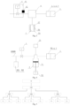
- FIG. 4 is a structural schematic diagram of a maintenance-free gas density relay for a high-voltage electrical apparatus or a gas density monitoring device in embodiment 4 of the present disclosure.
- the maintenance-free gas density relay or the gas density monitoring device of embodiment 4 of the present disclosure includes a gas density relay body 1 , a pressure sensor 21 , a pressure sensor 22 , a temperature transducer 31 , a temperature transducer 32 , a valve 4 , a pressure regulating mechanism 5 , an online check contact signal sampling unit 6 , an intelligent control unit 7 and an apparatus connecting joint 1010 .
- one end of the apparatus connecting joint 1010 is in sealed connection with a gas insulation electrical apparatus, and the other end of the apparatus connecting joint 1010 is in communication with the valve 4 ; and the other end of the valve 4 is in communication with the pressure regulating mechanism 5 .
- the gas density relay body 1 , the temperature transducer 31 , the online check contact signal sampling unit 6 and the intelligent control unit 7 are arranged together and are arranged on the pressure regulating mechanism 5 ; and the pressure sensor 21 is arranged on the pressure regulating mechanism 5 .
- the pressure sensor 22 and the temperature transducer 32 are arranged on the side of the apparatus connecting joint 1010 side (the side of the valve 4 connected to the apparatus connecting joint 1010 ).
- the pressure sensor 21 and a pressure detector of the gas density relay body 1 are in communication with the pressure regulating mechanism 5 on gas paths; the pressure sensor 21 , the pressure sensor 22 , the temperature transducer 31 and the temperature transducer 32 are connected to the intelligent control unit 7 ; the valve 4 is connected to the intelligent control unit 7 ; and the pressure regulating mechanism 5 is connected to the intelligent control unit 7 .
- the two pressure sensors are arranged and are the pressure sensor 21 and the pressure sensor 22 respectively; the two temperature transducers are arranged and are the temperature transducer 31 and the temperature transducer 32 respectively.
- the temperature transducer 32 may be omitted in this case.
- the maintenance-free gas density relay or the gas density monitoring device of embodiment 4 of the present disclosure is provided with several pressure sensors and several temperature transducers.
- a mutual self-check unit consists of two gas density detection sensors A and B. Specifically, pressure values PA and PB respectively detected by gas density detection sensors A and B (the pressure sensor 21 , the pressure sensor 22 , the temperature transducer 31 and the temperature transducer 32 ) are utilized for comparison, temperature values T A and T B are utilized for comparison, and if consistency of the pressure values is optimal, it is indicated that an online monitoring part of the gas density relay or the gas density monitoring device works normally without maintenance.
- the maintenance-free gas density relay for a gas insulation high-voltage electrical apparatus or the gas density monitoring device provided by embodiment 4 of the present disclosure has a safety protection function, which is specifically as follows: 1) no matter according to the pressure sensor 21 and the temperature transducer 31 , or according to the pressure sensor 22 and the temperature transducer 32 , as long as a monitored density value is lower than a set value, the gas density relay automatically does not check the gas density relay body 1 any more and sends out a notification signal; For example, when the gas density value of the apparatus is less than the set value, check is not carried out. Only when the gas density value of the apparatus ⁇ (blocking pressure+0.02 MPa), check may be carried out. A contact alarm has status indication.
- the gas density relay automatically no longer checks the gas density relay body 1 and sends out the notification signal (gas leakage). For example, when the gas density value of the apparatus is less than the set value (blocking pressure+0.02 MPa), check is not carried out.
- the set value may be set as required.
- the gas density relay further has mutual check of the plurality of pressure sensors and the plurality of temperature sensors, and mutual check of the pressure sensors, the temperature transducers and the gas density relay body 1 , so as to ensure normal work of the gas density relay.
- the gas density relay may compare error performance of the gas density relay at different temperatures in different time periods. That is, the performance of the electrical apparatus and the performance of the gas density relay are determined by means of comparison in different periods and at the same temperature range.
- the gas density relay has comparison of each period of the history and comparison of the history and the present, and may further be examined.
- the gas density relay may be repeatedly checked for multiple times (for example, 2-3 times), and according to a check result each time, average values of the check results may be computed. In necessary, the density relay may be checked online at any time.
- the types of the pressure sensors include absolute pressure sensors, relative pressure sensors, or absolute pressure sensors and relative pressure sensors, and the several pressure sensors may be arranged.
- the pressure sensors may be in the form of diffused silicon pressure sensors, micro electro mechanical system (MEMS) pressure sensors, chip type pressure sensors, coil induction pressure sensors (for example, pressure measurement sensors having Bourdon tubes attached with induction coils), resistance pressure sensors (for example, pressure measurement sensors having Bourdon tubes attached with slide wire resistors), and may be analog quantity pressure sensors, or digital quantity pressure sensors.
- MEMS micro electro mechanical system
- Pressure acquisition is various pressure sensing elements of the pressure sensors, pressure transmitters, etc., for example, a diffused silicon type, a sapphire type, a piezoelectric type and a strain gauge type (a resistance strain gauge type and a ceramic strain gauge type).
- the temperature transducers may be thermocouples, thermistors, and semiconductor types, may be a contact type and a non-contact type, and may be thermal resistors and the thermocouples.
- various temperature sensing elements of the temperature transducers, temperature transmitters, etc. may be used for temperature acquisition.
- the gas density relay body includes a density relay having indication (a pointer display density relay, a digital display density relay, or a liquid crystal display density relay) and a density relay without indication (that is, a density switch).
- the gas density relay has pressure, temperature measurement and software conversion functions. On the premise that safe operation of the electrical apparatus is not affected, alarming and/or blocking contact action values and/or return values of the gas density relay may be detected online. Of course, the return values of alarming and/or blocking contact signals may not need to be tested as required.
- the intelligent control unit 7 mainly completes valve control, control of the pressure regulating mechanism and signal acquisition. That is, the basic requirements or functions of the intelligent control unit 7 are as follows: control over the valve 4 , control over the pressure regulating mechanism 5 and signal acquisition are completed by means of the intelligent control unit 7 .
- the pressure values and the temperature values when a contact signal of the gas density relay body acts may be detected and converted into pressure values P 20 (density values) corresponding to 20° C., that is, contact action values P D20 of the gas density relay may be detected to complete check work of the gas density relay body.
- the density values P D20 when the contact signal of the gas density relay body acts may be directly detected to complete check work of the gas density relay body, which is the most basic requirement.
- the intelligent control unit 7 may further achieve: test data storage; and/or test data export; and/or test data printing; and/or may be in data communication with an upper computer; and/or may input analog or digital quantity information.
- the intelligent control unit 7 further includes a communication module, where long-distance transmission of information of test data, and/or check results, etc. is achieved by means of the communication module.
- a rated pressure value of the gas density relay body outputs a signal
- the intelligent control unit 7 acquires a current density value at the same time to complete check of the rated pressure value of the gas density relay.
- the gas density relay may automatically perform comparison and determination, and if an error difference is large, an abnormal prompt is sent out: the pressure detector or the pressure sensors, the temperature transducers, etc.
- the gas density relay may complete a mutual check function of the pressure detector, the pressure sensors, the temperature transducers, a density transmitter, etc. of the gas density relay, and may complete mutual check of the pressure detector, the pressure sensors, the temperature transducers, etc. of the gas density relay.
- the gas density relay completes check of the gas density relay, mutual comparison judgment is automatically carried out, and if the error difference is large, an abnormal prompt is sent out that a pressure detector or a pressure sensor, a temperature transducer and the like of the gas density relay have problems. That is, the gas density relay may complete mutual check functions of the pressure detector, or the pressure sensors, the temperature transducers, or the density transmitter of the gas density relay.
Landscapes
- Physics & Mathematics (AREA)
- General Physics & Mathematics (AREA)
- Fluid Mechanics (AREA)
- Chemical & Material Sciences (AREA)
- Pathology (AREA)
- Analytical Chemistry (AREA)
- Biochemistry (AREA)
- General Health & Medical Sciences (AREA)
- Health & Medical Sciences (AREA)
- Immunology (AREA)
- Life Sciences & Earth Sciences (AREA)
- Engineering & Computer Science (AREA)
- Power Engineering (AREA)
- Gas-Insulated Switchgears (AREA)
- Measuring Fluid Pressure (AREA)
- Switches Operated By Changes In Physical Conditions (AREA)
- Testing And Monitoring For Control Systems (AREA)
Abstract
Description
-
- 1, application No. being 201910830162.0 (title of invention: maintenance-free gas density relay) filed on Sep. 4, 2019; and
- 2, application No. being 202010416678.3 (title of invention: maintenance-free gas density relay) filed on May 15, 2020.
-
- a first aspect of the present disclosure discloses a maintenance-free gas density relay (or the gas density monitoring device), including: a gas density relay body, first gas density detection sensors and an intelligent control unit, where
- the first gas density detection sensors are in communication with the gas density relay body on gas paths and are used for acquiring pressure values and temperature values, and/or gas density values; the intelligent control unit is connected to the gas density relay body and/or the first gas density detection sensors, and receives and/or computes data monitored by the gas density relay body and the first gas density detection sensors;
- the intelligent control unit compares and checks a first pressure value and a second pressure value acquired at the same gas pressure; and/or the intelligent control unit compares and checks a first temperature value and a second temperature value acquired at the same gas temperature; or the intelligent control unit compares and checks a first density value and a second density value acquired at the same gas density to acquire a current working state of a monitoring part of the gas density relay; or,
- the intelligent control unit uploads received data to a background, and the background compares and checks the first pressure value and the second pressure value acquired at the same gas pressure; and/or the background compares and checks the first temperature value and the second temperature value acquired at the same gas temperature; or the background compares and checks the first density value and the second density value acquired at the same gas density to acquire the current working state of the monitoring part of the gas density relay,
- one or both of the first pressure value and the second pressure value being from the first gas density detection sensors or the gas density relay body, one or both of the first temperature value and the second temperature value being from the first gas density detection sensors or the gas density relay body, and one or both of the first density value and the second density value being from the first gas density detection sensors or the gas density relay body.
-
- the pressure values acquired by the pressure sensors and the temperature values acquired by the temperature transducers are fully permutated and combined, the combinations are converted into a plurality of pressure values corresponding to 20° C., that is, gas density values according to gas pressure-temperature characteristics, and the gas density values are compared to complete mutual check of the pressure sensors and the temperature transducers; or,
- the plurality of gas density values, the plurality of pressure values and the plurality of temperature values obtained by the pressure sensors and the temperature transducers are compared to complete mutual check of the gas density relay body, the pressure sensors and the temperature transducers. What is described above is completed by the background or the intelligent control unit.
-
- the temperature regulating mechanism includes a heating element, a heat insulation element, a temperature controller, a temperature detector and a temperature regulating mechanism outer shell. Or,
- the temperature regulating mechanism includes a heating element and a temperature controller; or,
- the temperature regulating mechanism includes a heating element, a heating power regulator and a temperature controller; or,
- the temperature regulating mechanism includes a heating element, a refrigeration element, a heating power regulator and a temperature controller; or,
- the temperature regulating mechanism includes a heating element, a heating power regulator and a thermostatic controller; or,
- the temperature regulating mechanism includes a heating element, a controller and a temperature detector; or,
- the temperature regulating mechanism is a heating element, and the heating element is arranged near the temperature compensation element of the gas density relay body; or,
- the temperature regulating mechanism is a miniature constant temperature box.
-
- the temperature controller is connected to the heating element and is used for controlling a heating temperature of the heating element, and the temperature controller includes, but not limited to, one of a proportion integration differentiation (PID) controller, a PID and fuzzy control combined controller, an inverter controller and a programmable logic controller (PLC).
-
- the pressure regulating mechanism is a cavity having an opening at one end, and the other end of the cavity is in communication with the gas density relay body; a piston is arranged in the cavity, one end of the piston is connected to a regulating rod, the outer end of the regulating rod is connected to a drive part, the other end of the piston extends into the opening and makes sealed contact with an inner wall of the cavity, and the drive part drives the regulating rod to drive the piston to move in the cavity; or,
- the pressure regulating mechanism is a closed air chamber, a piston is arranged inside the closed air chamber, the piston makes sealed contact with an inner wall of the closed air chamber, a drive part is arranged outside the closed air chamber, and the drive part pushes the piston to move in the cavity by means of an electromagnetic force; or,
- the pressure regulating mechanism is an airbag of which one end is connected to a drive part, the volume of the airbag is changed under the driving of the drive part, and the airbag is in communication with the gas density relay body; or,
- the pressure regulating mechanism is a bellow, one end of the bellow is in communication with the gas density relay body, and the other end of the corrugated pipe extends under the driving of the drive part; or,
- the pressure regulating mechanism is a deflation valve, and the deflation valve is a solenoid valve, a valve with electrically motorized operation or other deflation valves implemented in an electric or pneumatic mode; or,
- the pressure regulating mechanism is a compressor; or,
- the pressure regulating mechanism is a pump, and the pump includes, but not limited to, one of a pressure pump, a booster pump, an electrical gas pump and an electromagnetic gas pump.
-
- the gas density relay body further has a comparison pressure value output signal, and the comparison annunciator outputs the comparison pressure value output signal when gas pressure of the gas density relay body monitored by the pressure detector rises or falls to a set gas pressure value, and the comparison pressure value output signal is connected with the intelligent control unit; and/or,
- the gas density relay body further has a comparison density value output signal, and the comparison annunciator outputs the comparison density value output signal when gas density of the gas density relay body monitored by the pressure detector and the temperature compensation element rises or falls to a set gas density value, and the comparison density value output signal is connected to the intelligent control unit.
-
- setting a temperature interval step length within the set time interval, and computing an average value of the density values corresponding to N different temperature values acquired within all temperature ranges to obtain a gas density value; or,
- setting a pressure interval step length within the set time interval, and computing an average value of density values corresponding to N different pressure values acquired within all pressure change ranges to obtain a gas density value,
- where N is a positive integer greater than or equal to 1.
-
- the intelligent control unit acquires the pressure values and the temperature values acquired by the first gas density detection sensors when the gas density relay body is subjected to contact action or switching, and converts the pressure values and the temperature values into pressure values corresponding to 20° C., that is, gas density values according to gas pressure-temperature characteristics, so as to complete online check of the gas density relay (or the gas density monitoring device).
-
- communicating first gas density detection sensors with a gas density relay body on gas paths;
- connecting an intelligent control unit to the gas density relay body and/or the first gas density detection sensors; and
- comparing and checking, by the intelligent control unit, a first pressure value and a second pressure value acquired at the same gas pressure; and/or comparing and checking, by the intelligent control unit, a first temperature value and a second temperature value acquired at the same gas temperature; or comparing and checking, by the intelligent control unit, a first density value and a second density value acquired at the same gas density to acquire a current working state of a monitoring part of the gas density relay; or,
- uploading, by the intelligent control unit, received data to a background, and comparing and checking, by the background, the first pressure value and the second pressure value acquired at the same gas pressure; and/or comparing and checking, by the background, the first temperature value and the second temperature value acquired at the same gas temperature; or comparing and checking, by the background, the first density value and the second density value acquired at the same gas density to acquire the current working state of the monitoring part of the gas density relay,
- where one or both of the first pressure value and the second pressure value are from the first gas density detection sensors or the gas density relay body, one or both of the first temperature value and the second temperature value are from the first gas density detection sensors or the gas density relay body, and one or both of the first density value and the second density value are from the first gas density detection sensors or the gas density relay body.
-
- with a pressure value acquired by the pressure sensor of any one of the first gas density detection sensors and the second gas density detection sensors being a first pressure value PA, a temperature value acquired by the temperature transducer of any one of the first gas density detection sensors and the second gas density detection sensors being a first temperature value TA, a pressure value acquired by the pressure sensor of any another one of the first gas density detection sensors and the second gas density detection sensors being a second pressure value PB, and a temperature value acquired by the temperature transducer of any another one of the first gas density detection sensors and the second gas density detection sensors being a second temperature value TB, comparing, by the intelligent control unit or the background, the first pressure value PA with the second pressure value PB to acquire a pressure difference |PA−PB|, and comparing, by the intelligent control unit or the background, the first temperature value TA with the second temperature value TB to acquire a temperature difference |TA−TB|; and determining the current working state of the monitoring part of the gas density relay as a normal working state under the condition that the pressure difference |PA−PB| and/or the temperature difference |TA−TB| are/is within preset thresholds of the pressure difference and the temperature difference, and otherwise, determining the current working state of the monitoring part of the gas density relay as an abnormal working state; or,
- with a gas density value acquired by any one of the first gas density detection sensors and the second gas density detection sensors being a first density value PA20, and a gas density value acquired by any another one of the first gas density detection sensors and the second gas density detection sensors being a second density value PB20, comparing, by the intelligent control unit and/or the background, the first density value PA20 with the second density value PB20 to acquire a density difference |PA20−PB20|; and determining the current working state of the monitoring part of the gas density relay as the normal working state under the condition that the density difference |PA20−PB20| is within a preset threshold of the density difference, and otherwise, determining the current working state of the monitoring part of the gas density relay as the abnormal working state.
-
- with a temperature value acquired by any one of the temperature transducers being a first temperature value TA, and an ambient temperature value being a second temperature value TB, comparing, by the intelligent control unit and/or the background, the first temperature value TA with the second temperature value TB to acquire a temperature difference |TA−TB|; and determining the current working state of the monitoring part of the gas density relay as a normal working state without maintenance under the condition that the temperature difference |TA−TB| is within a preset threshold of the temperature difference, and otherwise, determining the current working state of the monitoring part of the gas density relay as an abnormal working state; or,
- with a pressure value acquired by any one of the pressure sensors being a first pressure value PA, and a pressure value acquired by any another one of the pressure sensors being a second pressure value PB, comparing, by the intelligent control unit and/or the background, the first pressure value PA with the second pressure value PB to acquire a pressure difference |PA−PB|; and determining the current working state of the monitoring part of the gas density relay as the normal working state without maintenance under the condition that the pressure difference |PA−PB| is within a preset threshold of the pressure difference, and otherwise, determining the current working state of the monitoring part of the gas density relay as the abnormal working state; or,
- with a temperature value acquired by any one of the temperature transducers being a first temperature value TA, and a temperature value acquired by any another one of the temperature transducers being a second temperature value TB, comparing, by the intelligent control unit and/or the background, the first temperature value TA with the second temperature value TB to acquire a temperature difference |TA−TB|; and determining the current working state of the monitoring part of the gas density relay as the normal working state without maintenance under the condition that the temperature difference |TA−TB| is within a preset threshold of the temperature difference, and otherwise, determining the current working state of the monitoring part of the gas density relay as the abnormal working state.
-
- randomly permutating and combining pressure values acquired by the pressure sensors and temperature values acquired by the temperature transducers, converting combinations into a plurality of pressure values corresponding to 20° C., that is, gas density values according to gas pressure-temperature characteristics, and comparing the gas density values to complete mutual check of the pressure sensors and the temperature transducers; or,
- fully permutating and combining the pressure values acquired by the pressure sensors and the temperature values acquired by the temperature transducers, converting the combinations into a plurality of pressure values corresponding to 20° C., that is, gas density values according to gas pressure-temperature characteristics, and comparing the gas density values to complete mutual check of the pressure sensors and the temperature transducers; or,
- comparing the plurality of gas density values, the plurality of pressure values and the plurality of temperature values obtained by the pressure sensors and the temperature transducers to complete mutual check of the gas density relay body, the pressure sensors and the temperature transducers.
-
- arranging the temperature regulating mechanism inside or outside a housing of the gas density relay body;
- connecting the temperature regulating mechanism to the intelligent control unit;
- with a contact signal value output when a contact of the gas density relay body acts and acquired by the intelligent control unit being a first density value PX20 and a preset contact signal value being a second density value PB20, comparing, by the intelligent control unit and/or the background, the first density value PX20 with the second density value PB20 to acquire a contact signal difference value |PX20−PB20|; and determining the current working state of the monitoring part of the gas density relay as a normal working state without maintenance under the condition that the contact signal difference value |PX20−PB20| is within a preset threshold of the contact signal difference value, and otherwise, determining the current working state of the monitoring part of the gas density relay as an abnormal working state.
-
- of the gas density relay body; and the mutual check method further includes:
- communicating a gas path of the pressure regulating mechanism with a gas path of the gas density relay body;
- connecting the pressure regulating mechanism to the intelligent control unit;
- with a contact signal value output when a contact of the gas density relay body acts and acquired by the intelligent control unit being a first density value PX20 and a preset contact signal value being a second density value PB20, comparing, by the intelligent control unit and/or the background, the first density value PX20 with the second density value PB20 to acquire a contact signal difference value |PX20−PB20|; and determining the current working state of the monitoring part of the gas density relay as a normal working state without maintenance under the condition that the contact signal difference value |PX20−PB20| is within a preset threshold of the contact signal difference value, and otherwise, determining the current working state of the monitoring part of the gas density relay as an abnormal working state.
-
- connecting the comparison pressure value output signal with the intelligent control unit; and/or,
- connecting the comparison density value output signal with the intelligent control unit;
- with the comparison pressure value output signal output by the comparison annunciator being a first pressure value PS, and pressure values acquired by the first gas density detection sensors at the same moment being second pressure values PJ, comparing, by the intelligent control unit and/or the background, the first pressure value PS with the second pressure values PJ to acquire pressure differences |PJ−PS|; and determining the current working state of the monitoring part of the gas density relay as a normal working state without maintenance under the condition that the pressure differences |PJ−PS| are within a preset threshold of the pressure differences, and otherwise, determining the current working state of the monitoring part of the gas density relay as an abnormal working state; and/or,
- with the comparison density value output signal output by the comparison annunciator being a first density value PS20, and gas density values acquired by the first gas density detection sensors at the same moment being second density values PJ20, comparing, by the intelligent control unit and/or the background, the first density value PS20 with the second density values PJ20 to acquire density differences |PJ20−PS20|; and determining the current working state of the monitoring part of the gas density relay as the normal working state without maintenance under the condition that the density differences |PJ20−PS20| are within a preset threshold of the density differences, and otherwise, determining the current working state of the monitoring part of the gas density relay as the abnormal working state.
-
- connecting the camera to the intelligent control unit;
- with a pointer display value or a number display value of the gas density relay body acquired by the camera by means of a head portrait recognition technology being a first density value PZ20 and gas density values acquired by the first gas density detection sensors at the same moment being second density values PJ20, comparing, by the intelligent control unit and/or the background, the first density value PZ20 with the second density values PJ20 to acquire density differences |PJ20−PZ20|; and determining the current working state of the monitoring part of the gas density relay as a normal working state without maintenance under the condition that the density differences |PJ20−PZ20| are within a preset threshold of the density differences, and otherwise, determining the current working state of the monitoring part of the gas density relay as an abnormal working state.
-
- 1) the maintenance-free gas density relay is provided, and further completes online self-check or mutual check of the gas density relay while being used for monitoring gas density of a gas-insulated or arc-control electrical apparatus, thereby improving efficiency, avoiding maintenance, reducing cost, and ensuring safe operation of a power grid.
- 2) the mutual check method for a maintenance-free gas density relay is provided, and may support normal operation of the above maintenance-free gas density relay.
-
- of which the purpose is that the pressure values monitored by the
pressure sensor 21 and thepressure sensor 22 may be compared and checked mutually; the pressure values monitored by the temperature sensor 31 and thetemperature sensor 32 may be compared and checked mutually; in addition, density values PA20 monitored by thepressure sensor 21 and the temperature transducer 31 and density values PB20 monitored by thepressure sensor 22 and thetemperature transducer 32 may be compared and checked mutually; and that is, the mutual self-check unit consists of a plurality of (at least two) gas density detection sensors A and B, and the density values PA20 and PB20 detected by the gas density detection sensors A and B respectively are compared, and if consistency of the density values is optimal, it is indicated that the online monitoring part of the gas density relay or the gas density monitoring device works normally without maintenance. That is, if |PA20−PB20| is within an allowable set value of |PA20−PB20|, the online monitoring part of the gas density relay or the density monitoring device works normally without maintenance.
- of which the purpose is that the pressure values monitored by the
Claims (18)
Applications Claiming Priority (5)
| Application Number | Priority Date | Filing Date | Title |
|---|---|---|---|
| CN201910830162.0A CN110534377A (en) | 2019-09-04 | 2019-09-04 | A kind of non-maintaining gas density relay |
| CN201910830162.0 | 2019-09-04 | ||
| CN202010416678.3 | 2020-05-15 | ||
| CN202010416678.3A CN111463063B (en) | 2019-09-04 | 2020-05-15 | Maintenance-free gas density relay |
| PCT/CN2020/111255 WO2021043042A1 (en) | 2019-09-04 | 2020-08-26 | Maintenance-free gas density relay and cross-checking method therefor |
Publications (2)
| Publication Number | Publication Date |
|---|---|
| US20220336169A1 US20220336169A1 (en) | 2022-10-20 |
| US12255032B2 true US12255032B2 (en) | 2025-03-18 |
Family
ID=68666551
Family Applications (1)
| Application Number | Title | Priority Date | Filing Date |
|---|---|---|---|
| US17/640,773 Active 2041-09-01 US12255032B2 (en) | 2019-09-04 | 2020-08-26 | Maintenance-free gas density relay and cross-checking method therefor |
Country Status (5)
| Country | Link |
|---|---|
| US (1) | US12255032B2 (en) |
| EP (1) | EP4027366A4 (en) |
| JP (1) | JP7661308B2 (en) |
| CN (3) | CN110534377A (en) |
| WO (1) | WO2021043042A1 (en) |
Families Citing this family (8)
| Publication number | Priority date | Publication date | Assignee | Title |
|---|---|---|---|---|
| CN110534377A (en) * | 2019-09-04 | 2019-12-03 | 上海乐研电气有限公司 | A kind of non-maintaining gas density relay |
| US12154738B2 (en) * | 2019-09-04 | 2024-11-26 | Shanghai Roye Electric Co., Ltd. | Method for modifying gas density relay, and gas density relay having online self-checking function and checking method therefor |
| CN111446116B (en) * | 2020-04-29 | 2025-07-01 | 上海乐研电气有限公司 | A self-diagnostic gas density relay and its use method |
| CN111446118B (en) * | 2020-04-29 | 2024-05-28 | 上海乐研电气有限公司 | Gas density relay with simulation verification function and simulation verification method thereof |
| CN111508770A (en) * | 2020-05-15 | 2020-08-07 | 上海乐研电气有限公司 | Digital gas density relay with self-diagnosis function and self-diagnosis method thereof |
| CN114279994B (en) * | 2021-11-19 | 2024-06-07 | 国网山东省电力公司电力科学研究院 | Substation gas on-line monitoring device and method suitable for gas relay |
| CN116559021A (en) * | 2023-05-08 | 2023-08-08 | 国网冀北电力有限公司电力科学研究院 | A highly shock-resistant and self-testing gas density relay and its self-testing method |
| CN120549401B (en) * | 2025-07-31 | 2025-10-03 | 佛山市顺德区美的洗涤电器制造有限公司 | Test system, test method and server of household appliance |
Citations (6)
| Publication number | Priority date | Publication date | Assignee | Title |
|---|---|---|---|---|
| JPS6093729A (en) | 1983-10-27 | 1985-05-25 | 日野自動車株式会社 | Pressure sensor |
| JPH10327514A (en) | 1997-05-23 | 1998-12-08 | Saginomiya Seisakusho Inc | Nonflammable gas pressure monitoring device, local monitoring device, nonflammable gas pressure monitoring system, and method of controlling nonflammable gas pressure monitoring device |
| CN206945915U (en) | 2017-06-01 | 2018-01-30 | 上海上芃电气有限公司 | A kind of SF6Gas density relay checking instrument |
| US20180284752A1 (en) * | 2016-05-09 | 2018-10-04 | StrongForce IoT Portfolio 2016, LLC | Methods and systems for industrial internet of things data collection in downstream oil and gas environment |
| CN207966854U (en) | 2018-03-23 | 2018-10-12 | 广东电网有限责任公司汕头供电局 | Multipurpose sulfur hexafluoride gas density relay device |
| CN110534377A (en) | 2019-09-04 | 2019-12-03 | 上海乐研电气有限公司 | A kind of non-maintaining gas density relay |
Family Cites Families (19)
| Publication number | Priority date | Publication date | Assignee | Title |
|---|---|---|---|---|
| JPS60190108U (en) * | 1984-05-28 | 1985-12-17 | 日新電機株式会社 | Automatic gas pressure monitoring device for gas insulated electrical equipment |
| US7127370B2 (en) * | 2000-01-07 | 2006-10-24 | Nocwatch International Inc. | Attitude indicator and activity monitoring device |
| CN2831095Y (en) * | 2005-05-27 | 2006-10-25 | 厦门Abb华电高压开关有限公司 | Gas density relay tester |
| FR2906653B1 (en) | 2006-09-28 | 2008-12-19 | Areva T & D Sa | DEVICE FOR MONITORING THE OPERATION OF A DENSIMETER FOR MEDIUM AND HIGH VOLTAGE ELECTRICAL APPARATUS AND METHOD FOR MONITORING THE OPERATION OF A DENSIMETER |
| CN1987412A (en) * | 2006-12-27 | 2007-06-27 | 郑州赛奥电子有限公司 | SF6 gas density relay corrector and its detecting method |
| CN201698958U (en) * | 2009-10-26 | 2011-01-05 | 江西省电力科学研究院 | A valve type SF6 gas density relay assembly joint |
| CN101937060B (en) * | 2010-09-09 | 2013-03-06 | 辽宁省电力有限公司抚顺供电公司 | Sulfur hexafluoride density relay calibration system and calibration method |
| US9362071B2 (en) | 2011-03-02 | 2016-06-07 | Franklin Fueling Systems, Inc. | Gas density monitoring system |
| CN104698372A (en) * | 2013-12-04 | 2015-06-10 | 上海乐研电气科技有限公司 | SF6 or mixed gas-containing density relay calibration device |
| CN104698371A (en) * | 2013-12-04 | 2015-06-10 | 上海乐研电气科技有限公司 | Multifunctional gas density relay calibration device |
| JP2015108561A (en) | 2013-12-05 | 2015-06-11 | 株式会社東芝 | Testing device of gas density switch |
| WO2015196955A1 (en) * | 2014-06-24 | 2015-12-30 | 江苏天舒电器有限公司 | Nitrogen-filling, pressure-keeping and leakage-detecting device for heat pump-refrigerating unit and control method therefor and device therefor |
| CN104375082A (en) * | 2014-11-04 | 2015-02-25 | 广州供电局有限公司 | Intelligent SF6 density relay calibration device and method |
| CN104616931B (en) * | 2015-02-02 | 2016-04-13 | 国家电网公司 | A kind of low temperature resistant digital SF6 relay |
| CN107064792B (en) * | 2017-06-01 | 2024-08-06 | 上海上芃电气有限公司 | SF (sulfur hexafluoride)6Gas density relay calibrator |
| CN108226768A (en) * | 2017-11-20 | 2018-06-29 | 国家电网公司 | Temperature-compensating check system and method |
| CN108107355B (en) * | 2017-12-20 | 2020-10-02 | 国网河北省电力有限公司电力科学研究院 | SF (sulfur hexafluoride)6And SF6Device and method for checking mixed gas density relay |
| CN108427088B (en) * | 2018-03-13 | 2024-05-03 | 中国大唐集团科学技术研究院有限公司华中分公司 | Online verification device and online verification method for density relay |
| CN108565170A (en) * | 2018-04-04 | 2018-09-21 | 佛山市威格特电气设备有限公司 | Intelligent SF6Air pressure early warning device |
-
2019
- 2019-09-04 CN CN201910830162.0A patent/CN110534377A/en active Pending
-
2020
- 2020-05-15 CN CN202110762706.1A patent/CN113539741B/en active Active
- 2020-05-15 CN CN202010416678.3A patent/CN111463063B/en active Active
- 2020-08-26 WO PCT/CN2020/111255 patent/WO2021043042A1/en not_active Ceased
- 2020-08-26 EP EP20861074.1A patent/EP4027366A4/en active Pending
- 2020-08-26 US US17/640,773 patent/US12255032B2/en active Active
- 2020-08-26 JP JP2022515121A patent/JP7661308B2/en active Active
Patent Citations (7)
| Publication number | Priority date | Publication date | Assignee | Title |
|---|---|---|---|---|
| JPS6093729A (en) | 1983-10-27 | 1985-05-25 | 日野自動車株式会社 | Pressure sensor |
| JPH10327514A (en) | 1997-05-23 | 1998-12-08 | Saginomiya Seisakusho Inc | Nonflammable gas pressure monitoring device, local monitoring device, nonflammable gas pressure monitoring system, and method of controlling nonflammable gas pressure monitoring device |
| US20180284752A1 (en) * | 2016-05-09 | 2018-10-04 | StrongForce IoT Portfolio 2016, LLC | Methods and systems for industrial internet of things data collection in downstream oil and gas environment |
| CN206945915U (en) | 2017-06-01 | 2018-01-30 | 上海上芃电气有限公司 | A kind of SF6Gas density relay checking instrument |
| CN207966854U (en) | 2018-03-23 | 2018-10-12 | 广东电网有限责任公司汕头供电局 | Multipurpose sulfur hexafluoride gas density relay device |
| CN110534377A (en) | 2019-09-04 | 2019-12-03 | 上海乐研电气有限公司 | A kind of non-maintaining gas density relay |
| CN111463063A (en) | 2019-09-04 | 2020-07-28 | 上海乐研电气有限公司 | Maintenance-free gas density relay |
Also Published As
| Publication number | Publication date |
|---|---|
| US20220336169A1 (en) | 2022-10-20 |
| EP4027366A1 (en) | 2022-07-13 |
| CN113539741A (en) | 2021-10-22 |
| WO2021043042A1 (en) | 2021-03-11 |
| CN110534377A (en) | 2019-12-03 |
| JP2022548539A (en) | 2022-11-21 |
| CN113539741B (en) | 2023-02-03 |
| CN111463063B (en) | 2021-08-10 |
| JP7661308B2 (en) | 2025-04-14 |
| CN111463063A (en) | 2020-07-28 |
| EP4027366A4 (en) | 2023-09-27 |
Similar Documents
| Publication | Publication Date | Title |
|---|---|---|
| US12255032B2 (en) | Maintenance-free gas density relay and cross-checking method therefor | |
| US12259300B2 (en) | Self-diagnostic gas density relay and use method thereof | |
| CN110530758B (en) | Gas density relay with online self-checking function and checking method thereof | |
| US12136530B2 (en) | Transformation method for gas density relay, and gas density relay having online self-check function and check method thereof | |
| CN111446113A (en) | Gas density relay with online self-checking function and checking method thereof | |
| CN111443283A (en) | Gas density relay online calibration device and online calibration method thereof | |
| US12154738B2 (en) | Method for modifying gas density relay, and gas density relay having online self-checking function and checking method therefor | |
| CN110441195B (en) | Gas density relay with online self-checking function and checking method thereof | |
| CN211426165U (en) | Gas density relay with online self-checking function and monitoring device | |
| CN110441680B (en) | Gas density relay with online self-checking function and checking method thereof | |
| CN211929384U (en) | A self-diagnostic gas density relay and gas density monitoring device | |
| CN212136345U (en) | Gas density relay with online self-checking function and monitoring device | |
| CN211718032U (en) | Gas density relay with online self-checking function and monitoring device | |
| CN211426166U (en) | Gas density relay with online self-checking function and monitoring device | |
| CN110514996B (en) | Transformation method of gas density relay | |
| CN110542852B (en) | Transformation method of gas density relay | |
| CN211318092U (en) | Gas density relay with online self-checking function and monitoring device | |
| CN211179416U (en) | Gas density relay with online self-checking function and monitoring device | |
| CN211179413U (en) | Gas density relay with online self-checking function and monitoring device | |
| CN210775758U (en) | Gas density relay with online self-checking function and monitoring device | |
| CN210489519U (en) | Multifunctional gas density relay | |
| CN212134890U (en) | Gas density relay with online self-checking function and monitoring device | |
| CN212646903U (en) | Online calibration device of gas density relay | |
| CN210668206U (en) | Multifunctional gas density relay |
Legal Events
| Date | Code | Title | Description |
|---|---|---|---|
| FEPP | Fee payment procedure |
Free format text: ENTITY STATUS SET TO UNDISCOUNTED (ORIGINAL EVENT CODE: BIG.); ENTITY STATUS OF PATENT OWNER: LARGE ENTITY |
|
| AS | Assignment |
Owner name: SHANGHAI ROYE ELECTRIC CO., LTD., CHINA Free format text: ASSIGNMENT OF ASSIGNORS INTEREST;ASSIGNORS:JIN, HAIYONG;XIA, TIEXIN;HUANG, XIAOBENG;AND OTHERS;REEL/FRAME:059191/0497 Effective date: 20220307 |
|
| STPP | Information on status: patent application and granting procedure in general |
Free format text: DOCKETED NEW CASE - READY FOR EXAMINATION |
|
| STPP | Information on status: patent application and granting procedure in general |
Free format text: NON FINAL ACTION MAILED |
|
| STPP | Information on status: patent application and granting procedure in general |
Free format text: RESPONSE TO NON-FINAL OFFICE ACTION ENTERED AND FORWARDED TO EXAMINER |
|
| STPP | Information on status: patent application and granting procedure in general |
Free format text: FINAL REJECTION MAILED |
|
| STPP | Information on status: patent application and granting procedure in general |
Free format text: RESPONSE AFTER FINAL ACTION FORWARDED TO EXAMINER |
|
| STPP | Information on status: patent application and granting procedure in general |
Free format text: ADVISORY ACTION MAILED |
|
| STPP | Information on status: patent application and granting procedure in general |
Free format text: NOTICE OF ALLOWANCE MAILED -- APPLICATION RECEIVED IN OFFICE OF PUBLICATIONS |
|
| STPP | Information on status: patent application and granting procedure in general |
Free format text: PUBLICATIONS -- ISSUE FEE PAYMENT VERIFIED |
|
| STCF | Information on status: patent grant |
Free format text: PATENTED CASE |