US12248623B2 - Display device and method of driving the same - Google Patents
Display device and method of driving the same Download PDFInfo
- Publication number
- US12248623B2 US12248623B2 US17/865,633 US202217865633A US12248623B2 US 12248623 B2 US12248623 B2 US 12248623B2 US 202217865633 A US202217865633 A US 202217865633A US 12248623 B2 US12248623 B2 US 12248623B2
- Authority
- US
- United States
- Prior art keywords
- area
- visual
- user
- viewing area
- frame
- Prior art date
- Legal status (The legal status is an assumption and is not a legal conclusion. Google has not performed a legal analysis and makes no representation as to the accuracy of the status listed.)
- Active
Links
Images


Classifications
-
- G—PHYSICS
- G09—EDUCATION; CRYPTOGRAPHY; DISPLAY; ADVERTISING; SEALS
- G09G—ARRANGEMENTS OR CIRCUITS FOR CONTROL OF INDICATING DEVICES USING STATIC MEANS TO PRESENT VARIABLE INFORMATION
- G09G5/00—Control arrangements or circuits for visual indicators common to cathode-ray tube indicators and other visual indicators
- G09G5/003—Details of a display terminal, the details relating to the control arrangement of the display terminal and to the interfaces thereto
- G09G5/005—Adapting incoming signals to the display format of the display terminal
-
- G—PHYSICS
- G02—OPTICS
- G02B—OPTICAL ELEMENTS, SYSTEMS OR APPARATUS
- G02B27/00—Optical systems or apparatus not provided for by any of the groups G02B1/00 - G02B26/00, G02B30/00
- G02B27/01—Head-up displays
- G02B27/017—Head mounted
-
- G—PHYSICS
- G02—OPTICS
- G02B—OPTICAL ELEMENTS, SYSTEMS OR APPARATUS
- G02B7/00—Mountings, adjusting means, or light-tight connections, for optical elements
- G02B7/28—Systems for automatic generation of focusing signals
- G02B7/287—Systems for automatic generation of focusing signals including a sight line detecting device
-
- G—PHYSICS
- G06—COMPUTING OR CALCULATING; COUNTING
- G06F—ELECTRIC DIGITAL DATA PROCESSING
- G06F3/00—Input arrangements for transferring data to be processed into a form capable of being handled by the computer; Output arrangements for transferring data from processing unit to output unit, e.g. interface arrangements
- G06F3/01—Input arrangements or combined input and output arrangements for interaction between user and computer
- G06F3/011—Arrangements for interaction with the human body, e.g. for user immersion in virtual reality
- G06F3/012—Head tracking input arrangements
-
- G—PHYSICS
- G06—COMPUTING OR CALCULATING; COUNTING
- G06F—ELECTRIC DIGITAL DATA PROCESSING
- G06F3/00—Input arrangements for transferring data to be processed into a form capable of being handled by the computer; Output arrangements for transferring data from processing unit to output unit, e.g. interface arrangements
- G06F3/01—Input arrangements or combined input and output arrangements for interaction between user and computer
- G06F3/011—Arrangements for interaction with the human body, e.g. for user immersion in virtual reality
- G06F3/013—Eye tracking input arrangements
-
- G—PHYSICS
- G06—COMPUTING OR CALCULATING; COUNTING
- G06F—ELECTRIC DIGITAL DATA PROCESSING
- G06F3/00—Input arrangements for transferring data to be processed into a form capable of being handled by the computer; Output arrangements for transferring data from processing unit to output unit, e.g. interface arrangements
- G06F3/14—Digital output to display device ; Cooperation and interconnection of the display device with other functional units
- G06F3/147—Digital output to display device ; Cooperation and interconnection of the display device with other functional units using display panels
-
- G—PHYSICS
- G09—EDUCATION; CRYPTOGRAPHY; DISPLAY; ADVERTISING; SEALS
- G09G—ARRANGEMENTS OR CIRCUITS FOR CONTROL OF INDICATING DEVICES USING STATIC MEANS TO PRESENT VARIABLE INFORMATION
- G09G3/00—Control arrangements or circuits, of interest only in connection with visual indicators other than cathode-ray tubes
- G09G3/20—Control arrangements or circuits, of interest only in connection with visual indicators other than cathode-ray tubes for presentation of an assembly of a number of characters, e.g. a page, by composing the assembly by combination of individual elements arranged in a matrix no fixed position being assigned to or needed to be assigned to the individual characters or partial characters
- G09G3/2007—Display of intermediate tones
-
- G—PHYSICS
- G09—EDUCATION; CRYPTOGRAPHY; DISPLAY; ADVERTISING; SEALS
- G09G—ARRANGEMENTS OR CIRCUITS FOR CONTROL OF INDICATING DEVICES USING STATIC MEANS TO PRESENT VARIABLE INFORMATION
- G09G5/00—Control arrangements or circuits for visual indicators common to cathode-ray tube indicators and other visual indicators
- G09G5/10—Intensity circuits
-
- G—PHYSICS
- G02—OPTICS
- G02B—OPTICAL ELEMENTS, SYSTEMS OR APPARATUS
- G02B27/00—Optical systems or apparatus not provided for by any of the groups G02B1/00 - G02B26/00, G02B30/00
- G02B27/01—Head-up displays
- G02B27/0101—Head-up displays characterised by optical features
- G02B2027/0138—Head-up displays characterised by optical features comprising image capture systems, e.g. camera
-
- G—PHYSICS
- G09—EDUCATION; CRYPTOGRAPHY; DISPLAY; ADVERTISING; SEALS
- G09G—ARRANGEMENTS OR CIRCUITS FOR CONTROL OF INDICATING DEVICES USING STATIC MEANS TO PRESENT VARIABLE INFORMATION
- G09G2310/00—Command of the display device
- G09G2310/02—Addressing, scanning or driving the display screen or processing steps related thereto
- G09G2310/0232—Special driving of display border areas
-
- G—PHYSICS
- G09—EDUCATION; CRYPTOGRAPHY; DISPLAY; ADVERTISING; SEALS
- G09G—ARRANGEMENTS OR CIRCUITS FOR CONTROL OF INDICATING DEVICES USING STATIC MEANS TO PRESENT VARIABLE INFORMATION
- G09G2310/00—Command of the display device
- G09G2310/02—Addressing, scanning or driving the display screen or processing steps related thereto
- G09G2310/0264—Details of driving circuits
- G09G2310/027—Details of drivers for data electrodes, the drivers handling digital grey scale data, e.g. use of D/A converters
-
- G—PHYSICS
- G09—EDUCATION; CRYPTOGRAPHY; DISPLAY; ADVERTISING; SEALS
- G09G—ARRANGEMENTS OR CIRCUITS FOR CONTROL OF INDICATING DEVICES USING STATIC MEANS TO PRESENT VARIABLE INFORMATION
- G09G2310/00—Command of the display device
- G09G2310/08—Details of timing specific for flat panels, other than clock recovery
-
- G—PHYSICS
- G09—EDUCATION; CRYPTOGRAPHY; DISPLAY; ADVERTISING; SEALS
- G09G—ARRANGEMENTS OR CIRCUITS FOR CONTROL OF INDICATING DEVICES USING STATIC MEANS TO PRESENT VARIABLE INFORMATION
- G09G2320/00—Control of display operating conditions
- G09G2320/06—Adjustment of display parameters
- G09G2320/0613—The adjustment depending on the type of the information to be displayed
-
- G—PHYSICS
- G09—EDUCATION; CRYPTOGRAPHY; DISPLAY; ADVERTISING; SEALS
- G09G—ARRANGEMENTS OR CIRCUITS FOR CONTROL OF INDICATING DEVICES USING STATIC MEANS TO PRESENT VARIABLE INFORMATION
- G09G2320/00—Control of display operating conditions
- G09G2320/06—Adjustment of display parameters
- G09G2320/068—Adjustment of display parameters for control of viewing angle adjustment
-
- G—PHYSICS
- G09—EDUCATION; CRYPTOGRAPHY; DISPLAY; ADVERTISING; SEALS
- G09G—ARRANGEMENTS OR CIRCUITS FOR CONTROL OF INDICATING DEVICES USING STATIC MEANS TO PRESENT VARIABLE INFORMATION
- G09G2320/00—Control of display operating conditions
- G09G2320/08—Arrangements within a display terminal for setting, manually or automatically, display parameters of the display terminal
-
- G—PHYSICS
- G09—EDUCATION; CRYPTOGRAPHY; DISPLAY; ADVERTISING; SEALS
- G09G—ARRANGEMENTS OR CIRCUITS FOR CONTROL OF INDICATING DEVICES USING STATIC MEANS TO PRESENT VARIABLE INFORMATION
- G09G2330/00—Aspects of power supply; Aspects of display protection and defect management
- G09G2330/02—Details of power systems and of start or stop of display operation
- G09G2330/021—Power management, e.g. power saving
- G09G2330/023—Power management, e.g. power saving using energy recovery or conservation
-
- G—PHYSICS
- G09—EDUCATION; CRYPTOGRAPHY; DISPLAY; ADVERTISING; SEALS
- G09G—ARRANGEMENTS OR CIRCUITS FOR CONTROL OF INDICATING DEVICES USING STATIC MEANS TO PRESENT VARIABLE INFORMATION
- G09G2340/00—Aspects of display data processing
- G09G2340/04—Changes in size, position or resolution of an image
- G09G2340/0464—Positioning
- G09G2340/0485—Centering horizontally or vertically
-
- G—PHYSICS
- G09—EDUCATION; CRYPTOGRAPHY; DISPLAY; ADVERTISING; SEALS
- G09G—ARRANGEMENTS OR CIRCUITS FOR CONTROL OF INDICATING DEVICES USING STATIC MEANS TO PRESENT VARIABLE INFORMATION
- G09G2354/00—Aspects of interface with display user
-
- G—PHYSICS
- G09—EDUCATION; CRYPTOGRAPHY; DISPLAY; ADVERTISING; SEALS
- G09G—ARRANGEMENTS OR CIRCUITS FOR CONTROL OF INDICATING DEVICES USING STATIC MEANS TO PRESENT VARIABLE INFORMATION
- G09G3/00—Control arrangements or circuits, of interest only in connection with visual indicators other than cathode-ray tubes
- G09G3/001—Control arrangements or circuits, of interest only in connection with visual indicators other than cathode-ray tubes using specific devices not provided for in groups G09G3/02 - G09G3/36, e.g. using an intermediate record carrier such as a film slide; Projection systems; Display of non-alphanumerical information, solely or in combination with alphanumerical information, e.g. digital display on projected diapositive as background
- G09G3/003—Control arrangements or circuits, of interest only in connection with visual indicators other than cathode-ray tubes using specific devices not provided for in groups G09G3/02 - G09G3/36, e.g. using an intermediate record carrier such as a film slide; Projection systems; Display of non-alphanumerical information, solely or in combination with alphanumerical information, e.g. digital display on projected diapositive as background to produce spatial visual effects
-
- G—PHYSICS
- G09—EDUCATION; CRYPTOGRAPHY; DISPLAY; ADVERTISING; SEALS
- G09G—ARRANGEMENTS OR CIRCUITS FOR CONTROL OF INDICATING DEVICES USING STATIC MEANS TO PRESENT VARIABLE INFORMATION
- G09G3/00—Control arrangements or circuits, of interest only in connection with visual indicators other than cathode-ray tubes
- G09G3/20—Control arrangements or circuits, of interest only in connection with visual indicators other than cathode-ray tubes for presentation of an assembly of a number of characters, e.g. a page, by composing the assembly by combination of individual elements arranged in a matrix no fixed position being assigned to or needed to be assigned to the individual characters or partial characters
- G09G3/22—Control arrangements or circuits, of interest only in connection with visual indicators other than cathode-ray tubes for presentation of an assembly of a number of characters, e.g. a page, by composing the assembly by combination of individual elements arranged in a matrix no fixed position being assigned to or needed to be assigned to the individual characters or partial characters using controlled light sources
- G09G3/30—Control arrangements or circuits, of interest only in connection with visual indicators other than cathode-ray tubes for presentation of an assembly of a number of characters, e.g. a page, by composing the assembly by combination of individual elements arranged in a matrix no fixed position being assigned to or needed to be assigned to the individual characters or partial characters using controlled light sources using electroluminescent panels
- G09G3/32—Control arrangements or circuits, of interest only in connection with visual indicators other than cathode-ray tubes for presentation of an assembly of a number of characters, e.g. a page, by composing the assembly by combination of individual elements arranged in a matrix no fixed position being assigned to or needed to be assigned to the individual characters or partial characters using controlled light sources using electroluminescent panels semiconductive, e.g. using light-emitting diodes [LED]
- G09G3/3208—Control arrangements or circuits, of interest only in connection with visual indicators other than cathode-ray tubes for presentation of an assembly of a number of characters, e.g. a page, by composing the assembly by combination of individual elements arranged in a matrix no fixed position being assigned to or needed to be assigned to the individual characters or partial characters using controlled light sources using electroluminescent panels semiconductive, e.g. using light-emitting diodes [LED] organic, e.g. using organic light-emitting diodes [OLED]
Definitions
- the present disclosure generally relates to a display device and a method of driving the same.
- a display device includes a display panel and a driver.
- the display panel may display an image on a display area corresponding to signals provided from the driver.
- an area visually recognized (or concentrated) by the user e.g., a viewing area or a recognition area
- unnecessary power consumption may occur in the area except the viewing area.
- Embodiments provide a display device capable of minimizing power consumption while not deteriorating the visibility of a user.
- a display device including: a visual sensor configured to generate visual sensing data by sensing an eye of a user; a display panel including a display area and pixels disposed on the display area; an image converter configured to generate a second image signal by converting a first image signal of the pixels based on the visual sensing data; and a data driver configured to provide the pixels with data signals corresponding to the second image signal, wherein the image converter generates visual information, based on the visual sensing data, determines a first area and a second area different from the first area of the display area based on the visual information, and generates the second image signal by converting grayscales of the second area in the first image signal.
- the image converter may decrease the grayscales of the second area.
- the image converter may convert the grayscales of the second area into grayscale 0.
- the image converter may include: a visual analyzer configured to generate first visual information corresponding to a line of a sight of the user and second visual information corresponding to a viewing angle of the user, based on the visual sensing data; a reference point extractor configured to determine a reference point corresponding to the line of the sight of the user on the display area based on the first visual information and generate reference point data corresponding to the reference point; an area extractor configured to detect a size of a visual area corresponding to the viewing angle of the user based on the second visual information and generate area data corresponding to the size of the visual area; and a viewing area determiner configured to determine the first area and the second area based on the reference point data and the area data, and generate visible area data corresponding to the first area and the second area.
- a visual analyzer configured to generate first visual information corresponding to a line of a sight of the user and second visual information corresponding to a viewing angle of the user, based on the visual sensing data
- a reference point extractor configured to determine a reference
- the visual analyzer may generate the first visual information from a position of a pupil of the eye of the user and generate the second visual information from a size of the pupil of the eye of the user based on the visual sensing data.
- the reference point extractor may determine a point at which an extension line corresponding to the line of the sight of the user and the display area meet each other as the reference point.
- the area extractor may detect the size of the visual area based on a distance between the display area and a certain point at a retina of the eye of the user in which an image is focused and the viewing angle of the user.
- the display device may further include a distance measuring sensor configured to measure the distance between the display area and the retina.
- the visual sensor may generate the visual sensing data in a first frame.
- the image converter may generate the second image corresponding to the first frame and the second image corresponding to a second frame consecutive to the first frame.
- the visual sensor may include a camera configured to acquire an image corresponding to the eye of the user by photographing the eye of the user.
- a method of driving a display device including a display area and pixels disposed on the display area, the method including: generating visual sensing data by sensing an eye of a user; generating visual information based on the visual sensing data; determining a first area and a second area different from the first area of the display area based on the visual information; specifying pixels corresponding to the second area among the pixels; generating a second image signal by converting grayscales of the pixels corresponding to the second area in a first image signal of the pixels; and providing the pixels with data signals corresponding to the second image signal.
- the grayscales of the pixels corresponding to the second area may be converted into grayscale 0.
- the generating of the visual information may include: generating first visual information corresponding to a line of a sight of the user based on the visual sensing data; and generating second visual information corresponding to a viewing angle of the user based on the visual sensing data.
- FIG. 1 is a block diagram illustrating a head mounted display device in accordance with embodiments of the present disclosure.
- FIG. 2 is a diagram illustrating an example in which a head mounted display device is implemented in accordance with embodiments of the present disclosure.
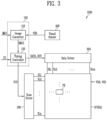
- FIG. 3 is a block diagram illustrating a display device in accordance with embodiments of the present disclosure.
- FIG. 4 is a block diagram illustrating an example of an image converter included in the display device shown in FIG. 3 .
- FIGS. 5 A, 5 B and 5 C are diagrams illustrating an example of operations of a visual analyzer, a reference point extractor, and an area extractor, which are included in the image converter shown in FIG. 4 .
- FIGS. 6 A, 6 B and 6 C are diagrams illustrating an example of a grayscale converter included in the image converter shown in FIG. 4 .
- FIG. 7 is a diagram illustrating an example of a visual sensor included in the display device shown in FIG. 3 .
- FIG. 1 is a block diagram illustrating a head mounted display device in accordance with embodiments of the present disclosure.
- the Head Mounted Display Device HMD may include a processor PRC, a memory device MEM, an input/output device IO, a power supply PS, a sensing device SD, and a display module DM.
- the components of the head mounted display device HMD are not limited to FIG. 1 , and the head mounted display device HMD may have components of which number is greater or smaller than that of the components shown in FIG. 1 .
- the processor PRC may perform specific calculations or tasks.
- the processor PRC may control overall operations of the head mounted display device HMD.
- the processor PRC may process signals, data information, and the like which are input through the input/output device IO, or drive an application program stored in the memory device MEM to provide a user with appropriate information or functions or to process the appropriate information or functions.
- the processor PRC may be a microprocessor, a Central Processing Unit (CPU), an Application Processor (AP), a Communication Processor (CP), or the like.
- the processor PRC may be connected to other components through an address bus, a control bus, a data bus, and the like.
- the processor PRC may be connected to an expansion bus such as a Peripheral Component Interconnection (PCI).
- PCI Peripheral Component Interconnection
- the memory device MEM may store data necessary for operations of the head mount device HMD.
- the memory device MEM may store a plurality of application programs for driving the head mounted display device HMD and data, commands, and the like for operations of the head mounted display device HMD. At least some of the plurality of application programs may be downloaded from an external server through the input/output device IO.
- the memory device MEM may include a nonvolatile memory device such as an Erasable Programmable Read Only Memory (EPROM), an Electrically Erasable Programmable Read Only Memory EEPROM, a flash memory, a Phase Change Random Access Memory (PRAM), a Resistance Random Access Memory (RRAM), a Magnetic Random Access Memory (MRAM), or a Ferroelectric Random Access Memory (FRAM), and/or a volatile memory device such as a Dynamic Random Access Memory (DRAM), a Static Random Access Memory (SRAM), or a mobile DRAM.
- EPROM Erasable Programmable Read Only Memory
- EEPROM Electrically Erasable Programmable Read Only Memory
- flash memory a Phase Change Random Access Memory (PRAM), a Resistance Random Access Memory (RRAM), a Magnetic Random Access Memory (MRAM), or a Ferroelectric Random Access Memory (FRAM)
- PRAM Phase Change Random Access Memory
- RRAM Resistance Random Access Memory
- MRAM Magnetic Random Access Memory
- FRAM Ferroelectric Random Access Memory
- the input/output device IO may include an input means including a camera or image input unit for image signal input, a microphone or audio input unit for audio signal input, a user input unit (e.g., a touch key, a push key, a joystick, a wheel key, or the like), and the like, and an output means including a sound output unit, a haptic module, an optical output unit, and the like which are used to generate an output associated with a sense of sight, a sense of hearing, a sense of touch, or the like.
- the display module DM may be provided in the input/output device IO.
- the power supply PS may supply power necessary for operations of the head mounted display device HMD.
- the power supply PS may supply external power and internal power to each of the components included in the head mounted display device HMD.
- the power supply PS may include a battery, and be implemented with an embedded battery or a replaceable battery.
- the sensing device SD may include at least one sensor for sensing peripheral environment information surrounding the head mounted display device HMD, user information, and the like.
- the sensing device SD may include an acceleration sensor, a gravity sensor, an illuminance sensor, a motion sensor, a fingerprint recognition sensor, an optical sensor, an ultrasonic sensor, a heat sensor, and the like.
- the display module DM may be connected to other components through the buses or another communication link.
- the display module DM may display information processed in the head mounted display device HMD.
- FIG. 2 is a diagram illustrating an example in which a head mounted display device is implemented in accordance with embodiments of the present disclosure.
- the head mounted display device HMD may include a display module DM, a housing HS, and a mounting part MT.
- the head mounted display device HMD may be mounted on a head of a user to provide image information to the user.
- the display module DM may display an image in response to an image signal.
- the display module DM may provide images respectively to left and right eyes of the user. A left-eye image corresponding to the left eye of the user and a right-eye image corresponding to the right eye of the user may be equal to or different from each other.
- the head mounted display device HMD may provide a 2D image, a 3D image, a virtual reality image, a 360-degree panoramic image, and the like through the display module DM.
- the display module DM may include at least one of a Liquid Crystal Display (LCD), an Organic Light Emitting Display (OLED), an inorganic light emitting display device, and a flexible display device.
- the display module DM may be built in the housing HS or be coupled to the housing HS.
- the display module DM may receive a command through an interface part or the like which is provided in the housing HS.
- the housing HS may be located at the front of the eyes of the user.
- the components for operating the head mounted display device HMD may be accommodated in the housing HS.
- a wireless communication part, an interface part, and the like may be located in the housing HS.
- the wireless communication part may receive an image signal from an external terminal by performing wireless communication with the external terminal.
- the wireless communication part may communicate with the external terminal by using Bluetooth, Radio Frequency Identification (RFID), Infrared Data Association (IrDA), Zigbee, Near Field Communication (NFC), Wireless-Fidelity (Wi-Fi), Ultra Wideband (UWB), or the like.
- the interface part may connect the head mounted display device HMD to an external device.
- the interface part of the head mounted display device HMD may include at least one of a wired/wireless headset port, an external charger port, a wired/wireless data port, a memory card port, an identification module port, an audio input/output (I/O) port, a video I/O port, and an earphone port.
- a wired/wireless headset port may include at least one of a wired/wireless headset port, an external charger port, a wired/wireless data port, a memory card port, an identification module port, an audio input/output (I/O) port, a video I/O port, and an earphone port.
- the mounting part MT may be connected to the housing HS to allow the head mounted display device HMD to be fixed to the head of the user.
- the mounting part MT may be implemented as a belt, a band having elasticity, or the like.
- the display panel DP may include a plurality of scan lines SL 1 to SLn (n is an integer greater than 0), a plurality of data lines DL 1 to DLm (m is an integer greater than 0), and a plurality of pixels PX.
- Each of the pixels PX may be connected to at least one of the scan lines SL 1 to SLn and at least one of the data lines DL 1 to DLm. Each of the pixels PX may emit light with a luminance corresponding to a data signal provided through a corresponding data line in response to a scan signal provided through a corresponding scan line. Meanwhile, the pixels PX may be supplied with voltages of a first power source VDD and a second power source VSS from the outside.
- the voltages of the first power source VDD and the second power source VSS are voltages necessary for an operation of the pixels PX.
- the first power source VDD may have a voltage level higher than that of the second power source VSS.
- Each of the pixels PX may include a light emitting element and a pixel driving circuit connected to the light emitting element.
- the light emitting element may be an organic light emitting diode or an inorganic light emitting diode such as a micro LED (light emitting diode) or a quantum dot light emitting diode.
- the light emitting element may be a light emitting element configured with a combination of an organic material and an inorganic material.
- each of the pixels PX may include a single light emitting element.
- each of the pixels PX may include a plurality of light emitting elements, and the plurality of light emitting element may be connected in series, parallel, or series/parallel to each other.
- the display panel DP may include a first sub-display area and a second sub-display area as the display area DA.
- the display panel DP may include a first sub-display area for displaying a left-eye image and a second sub-display area for displaying a right-eye image so as to provide images respectively to left and right eyes of a user.
- the image converter 110 may receive a first image signal IMG 1 from a processor (e.g., the processor PRC shown in FIG. 1 ) and receive visual sensing data VSD from the visual sensor 400 .
- the first image signal IMG 1 may include grayscales of each pixels in a frame.
- the line of sight of the user may be changed according to a viewing environment of the user, a change in the line of sight according to the movement of an image, and the like, and the field of view of the user may be changed since the size of pupils of the user is changed according to the luminance of the display image, the brightness of external light, or the like (e.g., the size of the pupils of the user becomes small when the luminance of the display image or the brightness of the external light is increased).
- the line of sight of the user and the field of view of the user are changed, an area in which the user visually recognizes an image in the display area DA may be changed.
- the head mounted display device HMD is mounted on a head of the user to provide a display image to the user, and therefore, the distance between the display module DM of the head mounted display device HMD (or the display panel DP of the display device 1000 shown in FIG. 3 ) and eyes of the user may be relatively close. Because the distance between the display module DM and the eyes of the user is relatively close, the size of the field of view of the user is limited. Therefore, the user may not visually recognize the entire area of the display area DA. That is, an area which is not visually recognized by the user (or is recognized relatively little by the user) in the display area DA may be existed.
- the timing controller 120 may receive a control signal CS from the processor (e.g., the processor PRC shown in FIG. 1 ).
- the control signal CS may include a horizontal synchronization signal, a vertical synchronization signal, a clock signal, and the like.
- the timing controller 120 generate a first control signal SCS and a second control signal DCS based on the control signal CS.
- the first control signal SCS may be provided to the scan driver 200 and the second control signal DCS may be provided to the data driver 300 .
- the image converter 110 and the timing controller 120 are components separate from each other has been illustrated in FIG. 3 , this is merely illustrative for convenience of description and the image converter 110 and the timing controller 120 may be integrally configured.
- the image converter 110 may be embedded in the timing controller 120 .
- the scan signal may include a gate-on voltage (e.g., a low voltage or a high voltage).
- a transistor receiving the gate-on voltage may be turned-on.
- the data driver 300 may receive the second control signal DCS and the image data DATA from the timing controller 120 .
- the data driver 300 may supply a data signal (or data voltage) corresponding to the second image IMG 2 (or the image data DATA) to the data lines DL 1 to DLm, in response to the second control signal DCS.
- the visual sensor 400 may generate visual sensing data VSD by sensing an eye of the user.
- the visual sensor 400 may include a camera which acquires an image corresponding to the eyes of the user by photographing the eyes of the user.
- the visual sensing data VSD may include the image corresponding to the eyes of the user.
- the visual sensor 400 may include an infrared camera using a bright pupil method or an infrared camera using a dark pupil method.
- the visual sensor 400 (or the infrared camera) may allow the center of a pupil of the eyes of the user to become bright by irradiating light (infrared light) to be parallel to a central axis of the pupil at a distance spaced apart from the eye of the user, which is an object to be detected, at a predetermined distance, and acquire an image corresponding to the eyes of the user by detecting light reflected from a retina of the eyes of the user.
- the visual sensor 400 may allow the center of the pupil of the eye of the user to become darker than an iris of the eye of the user by irradiating light (infrared light) to form a predetermined angle with the central axis of the pupil of the eyes of the user, which is an object to be detected, and acquire an image corresponding to the eyes of the user by detecting light reflected from the retina of the eyes of the user.
- the embodiment of the present disclosure is not limited thereto, and the visual sensor 400 may include both the infrared camera using the bright pupil method and the infrared camera using the dark pupil method.
- the camera included in the visual sensor 400 is implemented as an infrared camera, infrared light irradiated onto the eyes of the user to photograph the eyes of the user does not cause loss of the sight of the eyes of the user.
- the camera included in the visual sensor 400 is an infrared camera has been described in FIG. 3 , the present disclosure is not limited thereto.
- the camera included in the visual sensor 400 may be a visible light camera.
- the visual sensor 400 may acquire an image by photographing the eyes of the user for every frame.
- the visual sensor 400 may generate visual sensing data VSD and provide the generated visual sensing data VSD to the image converter 110 only when a change in size of the pupil of the user or a change in position of the pupil of the user is sensed in the image acquired by photographing the eyes of the user (i.e., only in a frame in which the change in size of the pupil of the user or the change in position of the pupil of the user is sensed). That is, the visual sensor 400 may generate visual sensing data VSD and provide the generated visual sensing data VSD to the image converter 110 , only when a change in visual information is sensed according to the image acquired by photographing the eye of the user.
- the visual sensor 400 may generate visual sensing data VSD and provide the generated visual sensing data VSD to the image converter 110 .
- the image converter 110 may extract visual information (e.g., first visual information and second visual information) by analyzing the visual sensing data VSD as described above. Therefore, the image converter 110 may determine a viewing area and a non-viewing area, and generate a second image signal IMG 2 by converting a first image signal IMG 1 .
- the visual sensor 400 may not provide the visual sensing data VSD to the image converter 110 .
- the image converter 110 may generate a second image signal IMG 2 by converting a first image signal IMG 1 of a corresponding frame (second frame) based on a viewing area and a non-viewing area which are determined corresponding to a previous frame (first frame). Since an operation in which the image converter 110 extracts visual information by analyzing the above-described visual sensing data VSD in the corresponding frame, or the like is omitted, the load according to a calculation operation of the image converter 110 can be decreased.
- the image converter 110 may further include a memory for storing information on the viewing area and the non-viewing area corresponding to the previous frame.
- the visual sensor 400 may be disposed on the housing HS of the head mounted display device HMD to sense the eyes of the user.
- the embodiment of the present disclosure is not limited thereto.
- the visual sensor 400 may be disposed in an area in which any image is not displayed on the display module DM to sense the eyes of the user.
- the visual sensor 400 may include two sub-visual sensors for respectively sensing the left and right eyes of the user.
- the image converter 110 may receive visual sensing data VSD respectively from the two sub-visual sensors, and generate second images signal IMG 2 by converting first images signal IMG 1 respectively corresponding to a left-eye image and a right-eye image.
- FIG. 4 is a block diagram illustrating an example of the image converter included in the display device shown in FIG. 3 .
- the image converter 110 may include a visual analyzer 111 , a reference point extractor 112 , an area extractor 113 , a viewing area determiner 114 , and a grayscale converter 115 .
- the visual analyzer 111 may generate first visual information VI 1 and second visual information VI 2 based on visual sensing data VSD.
- the visual analyzer 111 may generate the first visual information VI 1 including information ST 1 on the line of sight of the user viewing the display area DA and the second visual information VI 2 including information FV 1 on the field of view of the user by analyzing the visual sensing data VSD.
- the visual analyzer 111 may generate the first visual information VI 1 and the second visual information VI 2 by analyzing eye images of the user included in the visual sensing data VSD.
- a camera e.g., an infrared camera
- the visual analyzer 111 may extract a position and a size of the pupil of the eyes of the user by applying the eye images of the user to images of the eyes of the user which is modeled in advance.
- the visual analyzer 111 may extract the position and size of the pupil of the eyes of the user by using a regression model learning method.
- the operation in which the visual analyzer 111 extracts the position and size of the pupil of the eyes of the user is not limited thereto.
- the visual analyzer 111 may extract the position and size of the pupil of the eyes of the user by using a projection function, a Hough transform, or the like with respect to the eye images of the user.
- the visual analyzer 111 may estimate a line of sight of the user using the extracted position of the pupil (or a central position of the pupil), thereby generating the first visual information VI 1 .
- the visual analyzer 111 may estimate an extension line along a normal direction from a center of the pupil in the visual sensing data VSD as the line of sight of the user.
- the visual analyzer 111 may estimate a viewing angle of the user using the extracted size of the pupil in the visual sensing data VSD, thereby generating the second visual information VI 2 .
- the visual analyzer 111 may estimate a viewing angle corresponding to an area which is to be visually recognized to the user on the display area DA through the pupil from the retina by using the size of the pupil.
- the operation in which the visual analyzer 111 generates the first visual information VI 1 and the second visual information VI 2 by analyzing the visual sensing data VSD will be described in detail with reference to FIGS. 5 A to 5 C .
- the first visual information VI 1 may be provided to the reference point extractor 112 and the second visual information VI 2 may be provided to the area extractor 113 .
- the reference point extractor 112 may generate a reference point data RPD corresponding to a point (hereinafter, referred to as a reference point) corresponding to the line of sight of the user on the display area DA based on the first visual information VI 1 .
- the reference point extractor 112 may determine a point at which an extension line corresponding to the line of sight of the user and the display area DA meet each other as the reference point, thereby generating the reference point data RPD.
- the reference point is a point at which the line of sight of the user is most concentrated on the display area DA and may correspond to a center point in the viewing area described with reference to FIG. 3 .
- the area extractor 113 may generate area data AD corresponding to a size of an area visually recognized by the user (or visual area) based on the second visual information VI 2 .
- the area extractor 113 may generate the area data AD by detecting the size of an area visually recognized by the user (or visual area) by a viewing angle of the user.
- the size of the area visually recognized by the user may correspond to the viewing area described with reference to FIG. 3 .
- the reference point data RPD generated by the reference point extractor 112 and the area data AD generated by the area extractor 113 may be provided to the viewing area determiner 114 .
- the viewing area determiner 114 may generate visible area data VAD by detecting a viewing area corresponding to the area visually recognized by the user on the display area DA and a non-viewing area except the viewing area based on the reference point data RPD and the area data AD.
- the viewing area determiner 114 may determine a viewing area by setting a reference point corresponding to the reference point data RPD as the center point of the viewing area and setting a visual area corresponding to the area data AD as the viewing area.
- the grayscale converter 115 may receive a first image signal IMG 1 and convert the first image signal IMG 1 to a second image signal IMG 2 based on the viewing area data VAD provided from the viewing area determiner 114 .
- the grayscale converter 115 may specify pixels corresponding to the non-viewing area in the display area DA and generate the second image signal IMG 2 by converting grayscales of the pixels in the non-viewing area in the first image signal IMG 1 .
- the grayscale converter 115 may generate the second image signal IMG 2 by decreasing the grayscales of the pixels corresponding to the non-viewing area in the first image signal IMG 1 .
- the grayscale converter 115 may generate the second image signal IMG 2 by converting the grayscales of the pixels corresponding to the non-viewing area in the first image signal IMG 1 into grayscale 0. That is, grayscales of pixels corresponding to the non-viewing area among grayscales of the second image signal IMG 2 may be the grayscale 0. Accordingly, any image is not displayed in the non-viewing area in the display area DA (i.e., the pixels corresponding to the non-viewing area may be turned-off).
- the grayscale converter 115 may generate the second image signal IMG 2 by gradually decreasing the grayscales of the pixels corresponding to the non-viewing area in the first image signal IMG 1 such that the luminance of an image displayed in the non-viewing area gradually decreases as a distance from the viewing area increases.
- the grayscale converter 115 may generate the second image signal IMG 2 corresponding to the non-viewing area by multiplying a proportional constant to the first image signal IMG 1 .
- the proportional constant has a value which is greater than or equal to 0 and is less than 1, and may have a smaller value as the distant from the viewing area increases. Accordingly, the luminance of an image displayed in the non-viewing area in the display area DA may decrease as the distant from the viewing area increases.
- the image converter 110 in accordance with the embodiments of the present disclosure may generate first visual information VI 1 and second visual information VI 2 by analyzing visual sensing data VSD, determine a viewing area on the display area DA based on the first visual information VI 1 and the second visual information VI 2 , and generate a second image signal IMG 2 by converting grayscales corresponding to a non-viewing area except the viewing area among grayscales of a first image signal IMG 1 .
- the image converter 110 controls (e.g., decreases) the luminance of an image displayed on the non-viewing area of the display area DA in the second image signal IMG 2 , thereby decreasing power consumption.
- the non-viewing area corresponds to an area which is not visually recognized to the user (or is recognized relatively little by the user), the visibility of the user is not deteriorated even when the luminance is controlled in the non-viewing area.
- FIGS. 5 A and 5 C are diagrams illustrating an example of operations of the visual analyzer, the reference point extractor, and the area extractor which are included in the image converter shown in FIG. 4 .
- FIGS. 6 A to 6 C are diagrams illustrating an example of the grayscale converter included in the image converter shown in FIG. 4 .
- a virtual plane VP which corresponds to a surface of the display panel DP in the display area DA is illustrated in FIGS. 5 A to 5 C .
- the visual analyzer 111 may estimate an extension line along a normal direction at the first position P 1 with respect to the user eye UE having a spherical shape as a line of sight of the user (e.g., a first sight ST 1 ).
- the reference point extractor 112 may determine a point at which the line of sight (e.g., the first sight ST 1 ) of the user and the virtual plane VP meet each other as a reference point (e.g., a first reference point RP 1 ).
- the visual analyzer 111 may estimate a first viewing angle FOV 1 corresponding to an area (e.g., a first visual area A 1 ) which is to be visually recognized by the user through the pupil by using the first size T 1 .
- the viewing angle (e.g., the first viewing angle FOV 1 ) of the user may correspond to an angle formed between lines connecting both ends of the pupil PU to a certain point at a retina of the user eye UE in which an image is focused.
- the area extractor 113 may detect the first visual area A 1 (or an extent of the first visual area A 1 ) by using a distance S between the virtual plane VP and the certain point at the retina of the user eye UE and the first viewing angle FOV 1 .
- the visual sensor ( 400 shown in FIG. 3 ) in the display device ( 1000 shown in FIG. 3 ) may further include a distance measuring sensor.
- the distance measuring sensor may be an ultrasonic sensor which measures a distance between the retina of the user eye UE and the display panel DP (or the display area DA) by measuring a time for which an ultrasonic wave is reflected and then return.
- the embodiment of the present disclosure is not limited thereto, and the distance S between the retina of the user eye UE and the display area DA (i.e., the virtual plane VP) may have a predetermined value according to a device in which the display device ( 1000 shown in FIG. 3 ) is implemented, a viewing environment of the user, and the like.
- the display device ( 1000 shown in FIG. 3 ) is implemented as the head mounted display device (HMD shown in FIG. 2 )
- the distance between the user eye UE of the user wearing the head mounted display device HMD shown in FIG.
- the display panel DP and the display area DA may be determined according to the configuration of components (e.g., the display module DM, the housing HS, and the like) included in the head mounted display device (HMD shown in FIG. 2 ). Accordingly, the area extractor 113 can extract the first visual area A 1 (or an extent of the first visual area A 1 ) according to a viewing angle by using a predetermined distance S value without using a distance sensor.
- the area extractor 113 can extract the first visual area A 1 (or an extent of the first visual area A 1 ) according to a viewing angle by using a predetermined distance S value without using a distance sensor.
- the visual analyzer 111 may estimate an extension line along a normal direction at the second position P 2 with respect to the user eye UE as a line of sight of the user (e.g., a second sight ST 2 ).
- the reference point extractor 112 may determine a point at which the sight (e.g., the second sight ST 2 ) of the user which corresponds to the second position P 2 and the virtual plane VP meet each other as a reference point (e.g., a second reference point RP 2 ).
- a viewing angle estimated by the visual analyzer 111 in FIG. 5 B may be equal to the first viewing angle FOV 1 estimated by the visual analyzer 111 in FIG. 5 A
- an area (or an extent of the area) detected by the area extractor 113 in FIG. 5 B may be identical to the first visual area A 1 (or the extent of the first visual area A 1 ) detected by the area extractor 113 in FIG. 5 A .
- the viewing area determiner 114 may determine a viewing area (e.g., a second viewing area VA 2 ) which has an area equal to that of the first visual area A 1 by using a second reference point RP 2 as a center point, based on reference point data RPD and area data AD.
- a viewing area e.g., a second viewing area VA 2
- the viewing area determiner 114 may set a reference point corresponding to the reference point data RPD as a center point of the viewing area, and a reference point of the second viewing area VA 2 in FIG. 6 B may correspond to the second reference point RP 2 .
- the viewing area determiner 114 may set a visual area corresponding to the area data AD as the viewing area, and the second viewing area VA 2 in FIG. 6 B may correspond to the first visual area A 1 .
- the viewing area are the same, but the position of the viewing area may be changed.
- the viewing areas VA 1 and VA 2 are the same as that of the first visual area A 1 , but reference points of the viewing areas VA 1 and VA 2 may move from the first reference point RP 1 of the first viewing area VA 1 to the second reference point RP 2 of the second viewing area VA 2 .
- the visual analyzer 111 may estimate a second viewing angle FOV 2 corresponding to an area (e.g., a second visual area A 2 ) which the user can visually recognize through the pupil PU from the retina of the user eye UE by using the second size T 2 .
- the area extractor 113 may detect the second visual area A 2 (or an extent of the second visual area A 2 ) by using the distance S between the virtual plane VP and the retina of the user eye UE and the second viewing angle FOV 2 .
- the viewing angle may also become larger.
- the first viewing angle FOV 1 corresponding to the first size T 1 may be smaller than the second viewing angle FOV 2 corresponding to the second size T 2 .
- the second visual area A 2 may be wider than the first visual area A 1 .
- FIGS. 5 A and 5 C since central positions of the pupil PU of the user eye UE are the same as the first position P 1 , a line of sight of the user, which is estimated by the visual analyzer 111 , in FIG. 5 C may be identical to the first sight ST 1 estimated by the visual analyzer in FIG. 5 A , and a reference point determined by the reference point extractor 112 in FIG. 5 C may be equal to the first reference point RP 1 determined by the reference point extractor 112 in FIG. 5 A .
- the viewing area determiner 114 may determine a viewing area (e.g., a third viewing area VA 3 ) which has an area equal to that of the second visual area A 2 (e.g., wider than the first visual area A 1 ) by using the first reference point RP 1 as a center point based on reference point data RPD and area data AD.
- the viewing area determiner 114 may set a reference point corresponding to the reference point data RPD as a center point of the viewing area, and a reference point of the third viewing area VA 3 in FIG. 6 C may correspond to the first reference point RP 1 .
- the viewing area determiner 114 may determine a visual area corresponding to area data AD as the viewing area, and the third viewing area VA 3 in FIG. 6 C may correspond to the second visual area A 2 .
- the viewing areas VA 1 and VA 3 are the same as the first reference point RP 1 , but the viewing areas VA 1 and VA 3 may be changed from the first viewing area VA 1 (e.g., the extent of the first visual area A 1 ) to the third viewing area VA 3 (e.g., the extent of the second visual area A 2 ).
- the grayscale converter 115 may generate a second image signal IMG 2 by converting grayscales of pixels corresponding to a non-viewing area in a first image signal IMG 1 .
- the grayscale converter 115 may convert grayscales of pixels corresponding to a first non-viewing area NVA 1 in the first image signal IMG 1 .
- the grayscale converter 115 may convert grayscales of pixels corresponding to a second non-viewing area NVA 2 in the first image signal IMG 1 .
- the grayscale converter 115 may convert grayscales of pixels corresponding to a third non-viewing area NVA 3 in the first image signal IMG 1 .
- FIG. 7 is a diagram illustrating an example of the visual sensor included in the display device shown in FIG. 3 .
- the visual sensor 400 may include two sub-visual sensors.
- the visual sensor 400 may include sub-visual sensors 400 a and 400 b which generate visual sensing data VSD by respectively sensing a left eye UEa and a right eye UEb of a user eye UE.
- the user eye UE may include the left eye UEa and the right eye UEb. It is necessary to generate visual sensing data VSD about each of a left-eye image (e.g., an image provided on a first sub-display area DA 1 ) and a right-eye image (e.g., an image provided on a second sub-display area DA 2 ) because the visual sensing data VSD of a left-eye image and a right-eye image may be different according to a distance between the left eye UEa and the right eye UEb, a central position and a size difference between a pupil PUa of the left eye UEa and a pupil Pub of the right eye UEb due to a viewing environment and a display image, and the like.
- a left-eye image e.g., an image provided on a first sub-display area DA 1
- a right-eye image e.g., an image provided on a second sub-display area DA 2
- a first sub-visual sensor 400 a may generate visual sensing data VSD by sensing the left eye UEa.
- the image converter 110 may determine a left-eye viewing area corresponding to the left eye UEa on the first sub-display area DA 1 by detecting a reference point RPa and a visual area Aa (or viewing angle FOVa) according to a central position and a size of the pupil PUa of the left eye UEa based on the visual sensing data VSD, and generate a second image signal IMG 2 by converting a first image IMG 1 signal corresponding to the left-eye image.
- a second sub-visual sensor 400 b may generate visual sensing data VSD by sensing the right eye UEb.
- the image converter 110 may determine a right-eye viewing area corresponding to the right eye UEb on the second sub-display area DA 2 by detecting a reference point RPb and a visual area Ab (or viewing angle FOVb) according to a central position and a size of the pupil PUb of the right eye UEb based on the visual sensing data VSD, and generate a second image signal IMG 2 by converting a first image signal IMG 1 corresponding to the right-eye image.
- Operations of the first sub-visual sensor 400 a and the second sub-visual sensor 400 b are substantially identical or similar to that of the visual sensor 400 described with reference to FIG. 3 , and an operation in which the image converter 110 generates the second image signal IMG 2 by converting the first image signal IMG 1 based on the visual sensing data VSD generated by each of the first sub-visual sensor 400 a and the second sub-visual sensor 400 b is substantially identical or similar to that in which the image converter 110 described with reference to FIGS. 3 to 6 C generates the second image signal IMG 2 by converting the first image signal IMG 1 based on the visual sensing data VSD generated by the visual sensor 400 . Therefore, overlapping descriptions will not be repeated.
- visual information is extracted by analyzing visual sensing data generated by sensing eyes of a user, and the luminance of an area which is not visually recognized to the user (or is recognized relatively little by the user) in a display area is controlled corresponding to the visual information. Accordingly, power consumption can be minimized while not deteriorating the visibility of the user.
Landscapes
- Engineering & Computer Science (AREA)
- Physics & Mathematics (AREA)
- Theoretical Computer Science (AREA)
- General Physics & Mathematics (AREA)
- General Engineering & Computer Science (AREA)
- Computer Hardware Design (AREA)
- Human Computer Interaction (AREA)
- Optics & Photonics (AREA)
- Controls And Circuits For Display Device (AREA)
- Control Of Indicators Other Than Cathode Ray Tubes (AREA)
Abstract
Description
Claims (19)
Applications Claiming Priority (2)
| Application Number | Priority Date | Filing Date | Title |
|---|---|---|---|
| KR1020210111922A KR102898611B1 (en) | 2021-08-24 | 2021-08-24 | Display device and method of driving the same |
| KR10-2021-0111922 | 2021-08-24 |
Publications (2)
| Publication Number | Publication Date |
|---|---|
| US20230069320A1 US20230069320A1 (en) | 2023-03-02 |
| US12248623B2 true US12248623B2 (en) | 2025-03-11 |
Family
ID=85285983
Family Applications (1)
| Application Number | Title | Priority Date | Filing Date |
|---|---|---|---|
| US17/865,633 Active US12248623B2 (en) | 2021-08-24 | 2022-07-15 | Display device and method of driving the same |
Country Status (3)
| Country | Link |
|---|---|
| US (1) | US12248623B2 (en) |
| KR (1) | KR102898611B1 (en) |
| CN (1) | CN115938329A (en) |
Citations (17)
| Publication number | Priority date | Publication date | Assignee | Title |
|---|---|---|---|---|
| KR100244764B1 (en) | 1997-05-23 | 2000-03-02 | 전주범 | Apparatus for offering virtual reality service using the iris pattern of user and method thereof |
| KR20140137949A (en) | 2013-05-24 | 2014-12-03 | 삼성디스플레이 주식회사 | Display Device and Method of Driving thereof |
| JP2015073171A (en) | 2013-10-02 | 2015-04-16 | キヤノン株式会社 | Image processing apparatus, image processing method, and program |
| US20160012274A1 (en) * | 2014-07-09 | 2016-01-14 | Pixart Imaging Inc. | Vehicle safety system and operating method thereof |
| US20160133221A1 (en) * | 2014-11-10 | 2016-05-12 | Dell Products, Lp | Gaze Driven Display Front of Screen Performance |
| US20160238845A1 (en) * | 2015-02-17 | 2016-08-18 | Thalmic Labs Inc. | Systems, devices, and methods for eyebox expansion in wearable heads-up displays |
| US20180292896A1 (en) * | 2017-04-06 | 2018-10-11 | Intel Corporation | Head-mounted display device |
| JP2019074589A (en) | 2017-10-13 | 2019-05-16 | キヤノン株式会社 | Optical equipment |
| US20200264434A1 (en) * | 2018-12-26 | 2020-08-20 | Lg Electronics Inc. | Electronic device |
| US20200301161A1 (en) * | 2019-03-20 | 2020-09-24 | Nintendo Co., Ltd. | Image display system, non-transitory storage medium having stored therein image display program, image display apparatus, and image display method |
| US20210048668A1 (en) * | 2018-03-05 | 2021-02-18 | Magic Leap, Inc. | Display system with low-latency pupil tracker |
| KR20210062962A (en) | 2019-11-22 | 2021-06-01 | 유엔젤주식회사 | Pupil tracking based virtual content display device and control method thereof |
| KR102270577B1 (en) | 2014-10-21 | 2021-06-29 | 현대모비스 주식회사 | Apparatus and method for controlling outputting external image of vehicle |
| US20210225303A1 (en) * | 2019-01-04 | 2021-07-22 | Beijing Boe Optoelectronics Technology Co., Ltd. | Method and computer-readable medium for displaying image, and display device |
| US20210382325A1 (en) * | 2020-06-08 | 2021-12-09 | Acucela Inc. | Projection of defocused images on the peripheral retina to treat refractive error |
| US20220207664A1 (en) * | 2020-12-30 | 2022-06-30 | Quanta Computer Inc. | Computer apparatus and method for detecting defects in near-eye display |
| US20230029822A1 (en) * | 2020-01-22 | 2023-02-02 | Sony Group Corporation | Display device |
-
2021
- 2021-08-24 KR KR1020210111922A patent/KR102898611B1/en active Active
-
2022
- 2022-03-29 CN CN202210324600.8A patent/CN115938329A/en active Pending
- 2022-07-15 US US17/865,633 patent/US12248623B2/en active Active
Patent Citations (17)
| Publication number | Priority date | Publication date | Assignee | Title |
|---|---|---|---|---|
| KR100244764B1 (en) | 1997-05-23 | 2000-03-02 | 전주범 | Apparatus for offering virtual reality service using the iris pattern of user and method thereof |
| KR20140137949A (en) | 2013-05-24 | 2014-12-03 | 삼성디스플레이 주식회사 | Display Device and Method of Driving thereof |
| JP2015073171A (en) | 2013-10-02 | 2015-04-16 | キヤノン株式会社 | Image processing apparatus, image processing method, and program |
| US20160012274A1 (en) * | 2014-07-09 | 2016-01-14 | Pixart Imaging Inc. | Vehicle safety system and operating method thereof |
| KR102270577B1 (en) | 2014-10-21 | 2021-06-29 | 현대모비스 주식회사 | Apparatus and method for controlling outputting external image of vehicle |
| US20160133221A1 (en) * | 2014-11-10 | 2016-05-12 | Dell Products, Lp | Gaze Driven Display Front of Screen Performance |
| US20160238845A1 (en) * | 2015-02-17 | 2016-08-18 | Thalmic Labs Inc. | Systems, devices, and methods for eyebox expansion in wearable heads-up displays |
| US20180292896A1 (en) * | 2017-04-06 | 2018-10-11 | Intel Corporation | Head-mounted display device |
| JP2019074589A (en) | 2017-10-13 | 2019-05-16 | キヤノン株式会社 | Optical equipment |
| US20210048668A1 (en) * | 2018-03-05 | 2021-02-18 | Magic Leap, Inc. | Display system with low-latency pupil tracker |
| US20200264434A1 (en) * | 2018-12-26 | 2020-08-20 | Lg Electronics Inc. | Electronic device |
| US20210225303A1 (en) * | 2019-01-04 | 2021-07-22 | Beijing Boe Optoelectronics Technology Co., Ltd. | Method and computer-readable medium for displaying image, and display device |
| US20200301161A1 (en) * | 2019-03-20 | 2020-09-24 | Nintendo Co., Ltd. | Image display system, non-transitory storage medium having stored therein image display program, image display apparatus, and image display method |
| KR20210062962A (en) | 2019-11-22 | 2021-06-01 | 유엔젤주식회사 | Pupil tracking based virtual content display device and control method thereof |
| US20230029822A1 (en) * | 2020-01-22 | 2023-02-02 | Sony Group Corporation | Display device |
| US20210382325A1 (en) * | 2020-06-08 | 2021-12-09 | Acucela Inc. | Projection of defocused images on the peripheral retina to treat refractive error |
| US20220207664A1 (en) * | 2020-12-30 | 2022-06-30 | Quanta Computer Inc. | Computer apparatus and method for detecting defects in near-eye display |
Also Published As
| Publication number | Publication date |
|---|---|
| KR102898611B1 (en) | 2025-12-12 |
| KR20230030126A (en) | 2023-03-06 |
| US20230069320A1 (en) | 2023-03-02 |
| CN115938329A (en) | 2023-04-07 |
Similar Documents
| Publication | Publication Date | Title |
|---|---|---|
| CN115039168B (en) | Display control method and electronic device supporting same | |
| US11967263B2 (en) | Display screen control method and electronic device supporting same | |
| US12063346B2 (en) | Electronic device for displaying content and method of operation thereof | |
| CN106462339B (en) | Terminal and method for detecting ambient light brightness | |
| KR102560800B1 (en) | Electronic device for recognizing fingerprint using display | |
| KR102765379B1 (en) | Electronic device for dynamically adjusting the refresh rate of the display | |
| KR102761101B1 (en) | Operating Method for display and electronic device supporting the same | |
| KR20190134370A (en) | Electronic device and method for displaying content of application through display | |
| KR102640424B1 (en) | Foldable electronic device for detecting defective region and method thereof | |
| US20250118235A1 (en) | Electronic device and method for partially controlling brightness of flexible display on basis of shape of flexible display | |
| US12248623B2 (en) | Display device and method of driving the same | |
| KR102674204B1 (en) | Method for controlling the display and the electronic device supporting the same | |
| US12524065B2 (en) | Electronic apparatus and controlling method thereof | |
| US12387639B2 (en) | Display device, method for driving the same, and head-mounted display apparatus | |
| US20250006098A1 (en) | Display module, display device including the same, and method of operating the same | |
| US11508336B2 (en) | Head mounted display device and driving method thereof | |
| KR102674197B1 (en) | An Electronic Device including a Display | |
| US12205545B2 (en) | Electronic device and method for driving display thereof | |
| KR102535918B1 (en) | Wearable device and method for adjusting an overdriving information of a display based on a motion information of a user | |
| CN110753878B (en) | Method and apparatus for driving still images and video for TIR-based image displays | |
| KR102555375B1 (en) | Electronic device for changinh brightness of image data output to edge area of display | |
| KR102549503B1 (en) | Display driver integrated circuit for synchronizing the ouput timing of images in low power mode | |
| KR20250007953A (en) | Electronic device including display operating with state for lower power consumption and method thereof |
Legal Events
| Date | Code | Title | Description |
|---|---|---|---|
| AS | Assignment |
Owner name: SAMSUNG DISPLAY CO., LTD., KOREA, REPUBLIC OF Free format text: ASSIGNMENT OF ASSIGNORS INTEREST;ASSIGNORS:LEE, TAE UN;PARK, SUNG HWAN;HYUN, CHANG HO;REEL/FRAME:060518/0890 Effective date: 20220527 |
|
| FEPP | Fee payment procedure |
Free format text: ENTITY STATUS SET TO UNDISCOUNTED (ORIGINAL EVENT CODE: BIG.); ENTITY STATUS OF PATENT OWNER: LARGE ENTITY |
|
| STPP | Information on status: patent application and granting procedure in general |
Free format text: DOCKETED NEW CASE - READY FOR EXAMINATION |
|
| STPP | Information on status: patent application and granting procedure in general |
Free format text: NON FINAL ACTION MAILED |
|
| STPP | Information on status: patent application and granting procedure in general |
Free format text: RESPONSE TO NON-FINAL OFFICE ACTION ENTERED AND FORWARDED TO EXAMINER |
|
| STPP | Information on status: patent application and granting procedure in general |
Free format text: FINAL REJECTION MAILED |
|
| STPP | Information on status: patent application and granting procedure in general |
Free format text: ADVISORY ACTION MAILED |
|
| STPP | Information on status: patent application and granting procedure in general |
Free format text: DOCKETED NEW CASE - READY FOR EXAMINATION |
|
| STPP | Information on status: patent application and granting procedure in general |
Free format text: NON FINAL ACTION MAILED |
|
| STPP | Information on status: patent application and granting procedure in general |
Free format text: RESPONSE TO NON-FINAL OFFICE ACTION ENTERED AND FORWARDED TO EXAMINER |
|
| STPP | Information on status: patent application and granting procedure in general |
Free format text: FINAL REJECTION MAILED |
|
| STPP | Information on status: patent application and granting procedure in general |
Free format text: RESPONSE AFTER FINAL ACTION FORWARDED TO EXAMINER |
|
| STPP | Information on status: patent application and granting procedure in general |
Free format text: ADVISORY ACTION MAILED |
|
| STPP | Information on status: patent application and granting procedure in general |
Free format text: NOTICE OF ALLOWANCE MAILED -- APPLICATION RECEIVED IN OFFICE OF PUBLICATIONS |
|
| ZAAB | Notice of allowance mailed |
Free format text: ORIGINAL CODE: MN/=. |
|
| STPP | Information on status: patent application and granting procedure in general |
Free format text: PUBLICATIONS -- ISSUE FEE PAYMENT RECEIVED |
|
| STPP | Information on status: patent application and granting procedure in general |
Free format text: PUBLICATIONS -- ISSUE FEE PAYMENT VERIFIED |
|
| STCF | Information on status: patent grant |
Free format text: PATENTED CASE |
|
| STPP | Information on status: patent application and granting procedure in general |
Free format text: NOTICE OF ALLOWANCE MAILED -- APPLICATION RECEIVED IN OFFICE OF PUBLICATIONS |
|
| STPP | Information on status: patent application and granting procedure in general |
Free format text: PUBLICATIONS -- ISSUE FEE PAYMENT VERIFIED |
|
| STCF | Information on status: patent grant |
Free format text: PATENTED CASE |