US12248193B2 - Mechanical performance of optical stranded cables - Google Patents
Mechanical performance of optical stranded cables Download PDFInfo
- Publication number
- US12248193B2 US12248193B2 US17/992,904 US202217992904A US12248193B2 US 12248193 B2 US12248193 B2 US 12248193B2 US 202217992904 A US202217992904 A US 202217992904A US 12248193 B2 US12248193 B2 US 12248193B2
- Authority
- US
- United States
- Prior art keywords
- jacket
- cable according
- cable
- strength member
- buffer tubes
- Prior art date
- Legal status (The legal status is an assumption and is not a legal conclusion. Google has not performed a legal analysis and makes no representation as to the accuracy of the status listed.)
- Active
Links
Images


Classifications
-
- G—PHYSICS
- G02—OPTICS
- G02B—OPTICAL ELEMENTS, SYSTEMS OR APPARATUS
- G02B6/00—Light guides; Structural details of arrangements comprising light guides and other optical elements, e.g. couplings
- G02B6/44—Mechanical structures for providing tensile strength and external protection for fibres, e.g. optical transmission cables
- G02B6/4401—Optical cables
- G02B6/4429—Means specially adapted for strengthening or protecting the cables
- G02B6/443—Protective covering
-
- G—PHYSICS
- G02—OPTICS
- G02B—OPTICAL ELEMENTS, SYSTEMS OR APPARATUS
- G02B6/00—Light guides; Structural details of arrangements comprising light guides and other optical elements, e.g. couplings
- G02B6/44—Mechanical structures for providing tensile strength and external protection for fibres, e.g. optical transmission cables
- G02B6/4401—Optical cables
- G02B6/441—Optical cables built up from sub-bundles
- G02B6/4413—Helical structure
-
- G—PHYSICS
- G02—OPTICS
- G02B—OPTICAL ELEMENTS, SYSTEMS OR APPARATUS
- G02B6/00—Light guides; Structural details of arrangements comprising light guides and other optical elements, e.g. couplings
- G02B6/44—Mechanical structures for providing tensile strength and external protection for fibres, e.g. optical transmission cables
- G02B6/4401—Optical cables
- G02B6/4429—Means specially adapted for strengthening or protecting the cables
- G02B6/443—Protective covering
- G02B6/4432—Protective covering with fibre reinforcements
- G02B6/4433—Double reinforcement laying in straight line with optical transmission element
-
- G—PHYSICS
- G02—OPTICS
- G02B—OPTICAL ELEMENTS, SYSTEMS OR APPARATUS
- G02B6/00—Light guides; Structural details of arrangements comprising light guides and other optical elements, e.g. couplings
- G02B6/44—Mechanical structures for providing tensile strength and external protection for fibres, e.g. optical transmission cables
- G02B6/4401—Optical cables
- G02B6/4429—Means specially adapted for strengthening or protecting the cables
- G02B6/4434—Central member to take up tensile loads
-
- G—PHYSICS
- G02—OPTICS
- G02B—OPTICAL ELEMENTS, SYSTEMS OR APPARATUS
- G02B6/00—Light guides; Structural details of arrangements comprising light guides and other optical elements, e.g. couplings
- G02B6/44—Mechanical structures for providing tensile strength and external protection for fibres, e.g. optical transmission cables
- G02B6/4401—Optical cables
- G02B6/4429—Means specially adapted for strengthening or protecting the cables
- G02B6/443—Protective covering
- G02B6/4431—Protective covering with provision in the protective covering, e.g. weak line, for gaining access to one or more fibres, e.g. for branching or tapping
-
- G—PHYSICS
- G02—OPTICS
- G02B—OPTICAL ELEMENTS, SYSTEMS OR APPARATUS
- G02B6/00—Light guides; Structural details of arrangements comprising light guides and other optical elements, e.g. couplings
- G02B6/44—Mechanical structures for providing tensile strength and external protection for fibres, e.g. optical transmission cables
- G02B6/4401—Optical cables
- G02B6/4429—Means specially adapted for strengthening or protecting the cables
- G02B6/44384—Means specially adapted for strengthening or protecting the cables the means comprising water blocking or hydrophobic materials
Definitions
- the present invention relates to a communications cable. More particularly, the present invention relates to a fiber optic communication cable with oversized filler rods to add crush resistance.
- Fiber optic cables with a plurality of buffer tubes such as six buffer tubes, stranded about a central strength member are well known in the existing art. See for example U.S. Published Application Nos. 2004/0071416 and 2015/0241652 and U.S. Pat. No. 7,203,405, each of which is incorporated herein by reference.
- Each buffer tube includes a plurality of optical fibers, such as eight or twelve optical fibers per buffer tube. When the fiber optic cable does not need so many optical fibers, it is common to replace one or more of the buffer tubes with a filler rod.
- FIG. 1 shows a cross sectional view of a prior art fiber optic cable 8 , wherein two side-by-side filler rods 18 , along with four buffer tubes 12 , are stranded around a central strength member 10 to form a cable core.
- the cable core is surrounded by a jacket 16 .
- each of the filler rods 18 is diametrically opposite a respective buffer tube 12 along the length of the fiber optic cable 8 .
- any one of diametrically opposed pinching forces A, B, C, D, E, F, G, H and I applied to the jacket 16 could lead to the crushing of a buffer tube 12 .
- FIGS. 1 and 2 herein are shown as FIGS. 2(a) and 2(b) in U.S. Pat. No. 7,203,405, as previously incorporated by reference.
- Crush occurs when the jacket 16 of the fiber optic cable 8 is subjected laterally to external pressures, such as when the cable is being pulled into a conduit and the jacket 16 is pulled against a conduit fitting, or an edge an enclosure opening, or even against a rigid adjacent cable, like a power cable.
- the fiber optic cable 8 is compressed and deformed. The deformation can crush the buffer tubes 12 and hence the optical fibers within the buffer tubes 12 . Compression of the optical fibers can lead to micro-bends and/or breakage of the optical fibers, causing transmission errors and/or transmission failure.
- FIG. 3 shows a cross sectional view of a prior art fiber optic cable 20 , wherein two diametrically opposed filler rods 28 , along with four buffer tubes 24 , are stranded around a central strength member 22 to form a cable core.
- the cable core is surrounded by a jacket 30 .
- the filler rods 28 are diametrically opposite to each other.
- the forces applied at C, F and I are supported by the filler rods 28 .
- the pinching forces applied to the jacket 30 at locations C, F and I are well supported by the abutments between the central strength member 22 and the filler rods 28 on either side of the central strength member 22 .
- FIGS. 3 and 4 herein are shown as FIGS. 3(a) and 3(b) in U.S. Pat. No. 7,203,405, and may be more fully understood with reference thereto.
- FIG. 5 shows a cross sectional view of a prior art fiber optic cable 20 A, wherein four diametrically opposed filler rods 28 , along with two buffer tubes 24 , are stranded around the central strength member 22 to form a cable core.
- the cable core is surrounded by the jacket 30 .
- FIG. 6 due to the stranding pattern around the central strength member 22 , the filler rods 28 are diametrically opposite to each other. Hence, as illustrated in FIG. 6 , with the diametrically opposed pinching forces A, B, C, D, E, F, G, H and I applied to the jacket 30 , the forces applied at B, C, E, F, H and I are supported by the filler rods 28 . In other words, the pinching forces applied to the jacket 30 at locations B, C, E, F, H and I are well supported by the abutments between the central strength member 22 and the filler rods 28 on either side of the central strength member 22 . Crush may occur to some degree when pinch forces are applied at locations A, D and G.
- FIG. 5 herein is shown as FIG. 4 in U.S. Pat. No. 7,203,405, and may be more fully understood with reference thereto.
- the Applicant has appreciated an improved cable core design to strengthen the cable core.
- the new design allows the jacket of the cable to experience a large lateral force, e.g., a pinching force, without crushing the buffer tubes within the cable core.
- a new internal geometry and relative sizing of the components of the cable core allow lateral forces applied to the cable jacket to be either wholly or partially redirected away from the buffer tubes. In either instance, the likelihood of crushing a buffer tube within the cable core is reduced. In other words, the buffer tubes are more protected than in the crush avoidance systems of the prior art.
- a cable with a cable core including a central strength member including a central strength member.
- a plurality of buffer tubes, with each buffer tube including a plurality of optical fibers therein, and a plurality of filler rods are stranded about the central strength member.
- the filler rods are diametrically opposite to each other within the cable core.
- a characterizing feature is that a diameter of each of the plurality of filler rods is larger than a diameter of each of the plurality of buffer tubes.
- a jacket surrounds the cable core.
- FIG. 1 is a cross sectional view of a first fiber optic cable in accordance with the prior art
- FIG. 2 is an illustration of the alignments of the elements within the fiber optic cable of FIG. 1 at different length locations along a jacket of the fiber optic cable;
- FIG. 3 is a cross sectional view of a second fiber optic cable in accordance with the prior art
- FIG. 4 is an illustration of the alignments of the elements within the fiber optic cable of FIG. 3 at different length locations along a jacket of the fiber optic cable;
- FIG. 5 is a cross sectional view of a third fiber optic cable in accordance with the prior art
- FIG. 6 is an illustration of the alignments of the elements within the fiber optic cable of FIG. 5 at different length locations along a jacket of the fiber optic cable;
- FIG. 7 is a front perspective view of a fiber optic cable in accordance with the present invention.
- FIG. 8 is a cross sectional view taken along line VIII-VIII in FIG. 7 ;
- FIG. 9 is an illustration of the alignments of the elements within the fiber optic cable of FIGS. 7 and 8 at different length locations along a jacket of the fiber optic cable.
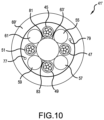
- FIG. 10 is a cross sectional view, similar to FIG. 8 , but illustrating alternative features for the fiber optic cable of FIGS. 7 and 8 .
- spatially relative terms such as “under”, “below”, “lower”, “over”, “upper”, “lateral”, “left”, “right” and the like, may be used herein for ease of description to describe one element or feature's relationship to another element(s) or feature(s) as illustrated in the figures. It will be understood that the spatially relative terms are intended to encompass different orientations of the device in use or operation in addition to the orientation depicted in the figures. For example, if the device in the figures is inverted, elements described as “under” or “beneath” other elements or features would then be oriented “over” the other elements or features. The device may be otherwise oriented (rotated 90 degrees or at other orientations) and the descriptors of relative spatial relationships used herein interpreted accordingly.
- FIG. 7 is a front perspective view of a fiber optic cable 41 in accordance with the present invention.
- FIG. 8 is a cross sectional view taken along line VIII-VIII in FIG. 7 .
- the fiber optic cable 41 includes an inner core 43 .
- the inner core 43 includes a plurality of buffer tubes, such as first, second, third and fourth buffer tubes 45 , 47 , 49 and 51 .
- Each of the first, second, third and fourth buffer tubes 45 , 47 , 49 and 51 has a diameter between 0.9 mm and 1.5 mm, such as between 1.1 mm and 1.3 mm, for example about 1.2 mm.
- Each of the first, second, third and fourth buffer tubes 45 , 47 , 49 and 51 includes a plurality of optical fibers 53 therein.
- each of the first, second, third and fourth buffer tubes 45 , 47 , 49 and 51 includes six optical fibers 53 .
- more or fewer optical fibers 53 may be included, and different numbers of optical fibers 53 may be included in each of the first, second, third and fourth buffer tubes 45 , 47 , 49 and 51 .
- a central strength member 63 is provided along a central axis X of the fiber optic cable 41 .
- a diameter of the central strength member 63 is between 1.9 mm and 2.9 mm, such as between 2.2 mm and 2.6 mm, for example about 2.4 mm.
- the central strength member 63 is formed of a core 65 surrounded by a sheath 67 , to form an up jacketed central strength member 63 .
- the sheath 67 When up-jacketed, the sheath 67 has an outer diameter of about 2.4 mm, while the core 65 may have a diameter of about 1.6 mm.
- the core 65 may be formed as a glass reinforced plastic (GRP) rod, while the sheath 67 may be formed of a polymer material, such as a low-smoke, zero-halogen polymer. If the sheath 67 is not used, the entire central strength member 63 may be formed as a GRP rod.
- GRP glass reinforced plastic
- a plurality of filler rods such as first, second, third and fourth filler rods 55 , 57 , 59 and 61 are stranded with the plurality of buffer tubes 45 , 47 , 49 and 51 around the central strength member 63 .
- the stranding may be in one direction, such as clockwise twisting of the buffer tubes 45 , 47 , 49 and 51 and the filler rods 55 , 57 , 59 and 61 about the central strength member 63 in FIG. 8 .
- the stranding is in a S-Z pattern with switchbacks, where the clockwise twisting about the central strength member 63 changes to counterclockwise and vice versa at the switchbacks along the length of the fiber optic cable 41 .
- Each of the first, second, third and fourth filler rods 55 , 57 , 59 and 61 has a diameter between 1.1 mm and 1.7 mm, such as between 1.3 mm and 1.6 mm, for example about 1.4 mm or about 1.5 mm.
- the first, second, third and fourth filler rods 55 , 57 , 59 and 61 are preferably formed of a low smoke zero halogen (LSZH) material.
- LSZH low smoke zero halogen
- a jacket 69 surrounds the cable core 41 .
- An outer diameter of the jacket 69 is between 7.0 mm and 9.4 mm, such as between 7.6 mm and 8.8 mm, for example 8.6 mm.
- the jacket 69 may be formed of any polymer material, however an ultra low smoke zero halogen (ULSZH) material is preferred.
- the jacket 69 may include one or more stripes of a contrasting color, to help identify the fiber optic cable 41 .
- the majority of the jacket 69 may be black and the one or more stripes of a red, yellow and/or green color may be embedded within or printed onto the jacket 69 .
- a characterizing feature is that a diameter of each filler rod of the plurality of filler rods 55 , 57 , 59 and 61 is more than 10% larger in diameter as compared to each buffer tube of the plurality of buffer tubes 45 , 47 , 49 and 51 .
- filler rods with a diameter of 1.4 mm are about 17% larger in diameter as compared to buffer tubes with a 1.2 mm diameter.
- the jacket 69 may optionally include first and second embedded strength members 71 and 73 therein.
- the first and second embedded strength members 71 and 73 are preferably GRP rods spaced one hundred eighty degrees apart from each other within a wall forming the jacket 69 .
- the first and second embedded strength members 71 and 73 could potentially be formed as metallic rods, so as to enable toning of the fiber optic cable 41 , should the fiber optic cable 41 need to be located underground or amongst a plurality of cables.
- FIGS. 7 and 8 also show a plurality of textile strength elements 75 , such as yarns, within the jacket 69 .
- the yarns surround the cable core 43 .
- the yarns may be formed into bundles of fibers, each of which extends longitudinally along the length of the fiber optic cable 41 .
- the yarns may be formed into a first grouping and a second grouping of yarns.
- the first grouping of yarns is helically wrapped around the cable core 43 in a first wrapping direction.
- the second grouping of yarns is helically wrapped around the cable core 43 in a second wrapping direction, opposite to the first wrapping direction.
- the first and second groupings of yarns cross over each other to hold the elements of the cable core 43 together during manufacturing of the fiber optic cable 41 .
- the textile strength elements 75 are formed of flaccid threads or yarns, like E-Glass strength members or aramid fibers, sold under the trademark KELVAR.
- the fiber optic cable includes at least one rip cord, such as first and second rip cords 77 and 79 within the jacket 69 .
- the first and second ripcords 77 and 79 assist in opening up an end of the fiber optic cable 41 for a termination to one or more connectors.
- the first and second rip cords 77 and 79 may also be formed of flaccid threads, like aramid threads, sold under the trademark KELVAR.
- FIGS. 7 and 8 also show at least one water blocking tape or thread, such as first and second water blocking threads 81 and 83 included within the cable core 43 .
- FIG. 9 shows the stranding pattern around the central strength member 63 , the first, second, third and fourth filler rods 55 , 57 , 59 and 61 are diametrically opposite to each other.
- the forces applied at A, C, E, G and I are supported by the filler rods 55 , 57 , 59 and 61 .
- the pinching forces applied to the jacket 69 at locations A, C, E, G and I are well supported by the abutments between the central strength member 63 and the filler rods 55 , 57 , 59 , and 61 on either side of the central strength member 63 .
- the oversized filler rods 55 , 57 , 59 and 61 act as supports to keep the force applied to the jacket 69 at locations B, D, F and H from reaching the buffer tubes 45 , 47 , 49 and 51 .
- the filler rods 55 , 57 , 59 and 61 act as table legs and the jacket 69 acts as a table top.
- the jacket 69 (table top) causes the force to be split and support by the first and second filler rods 55 and 57 .
- the first and second filler rods 55 and 57 directly abut the central strength member 63 .
- the jacket 69 would need to deform a significant amount before any of the force at location B would allow the jacket 69 to contact the second buffer tube 47 .
- FIG. 10 is a cross sectional view similar to FIG. 8 of a modified fiber optic cable 41 ′.
- the modified fiber optic cable 41 ′ is an alternative to the fiber optic cable 41 .
- the only changes are that the first and second embedded strength members 71 and 73 are not included within the jacket 69 ′, and the wall forming the jacket 69 ′ has been made thinner.
- the central strength member 63 ′ does not include a sheath 67 , and can be made of a smaller diameter, if desired.
- the filler rods 55 , 57 , 59 and 61 may also be made of a slightly smaller diameter, if desired.
- the changes result in the modified fiber optic cable 41 ′ having an overall diameter of about 7.8 mm.
- the filler rods 55 , 57 , 59 and 61 may be formed of a dielectric plastic, and directly abut the central strength member 63 .
- the central strength member 63 due to its embedded fiberglass segments, provides a high degree of strength to the fiber optic cable 41 , 41 ′.
- the filler rods 55 , 57 , 59 and 61 do not provide much added strength to the fiber optic cable 41 , 41 ′, but primarily assist in preventing a crushing of the buffer tubes 45 , 47 , 49 and 51 within cable core 43 .
- the filler rods 55 , 57 , 59 and 61 may also assist in keeping the overall outer cross sectional shape of the fiber optic cable 41 , 41 ′ circular, so that the fiber optic cable 41 , 41 ′ can be stored and transported on a reel and deployed in the field more easily.
- each buffer tube 45 , 47 , 49 and 51 has been illustrated as having six optical fibers 53 , other numbers of optical fibers 53 are possible, such as four, eight, ten or twelve optical fibers 53 , preferably surrounded by a gel, such as a water blocking gel, within the buffer tubes 45 , 47 , 49 and 51 .
- a gel such as a water blocking gel
- FIGS. 7 - 10 illustrated six optical fibers loosely contained within each of the four buffer tubes 45 , 47 , 49 and 51 , making a total of 24 optical fibers in the fiber optic cable 41 , 41 ′.
Landscapes
- Physics & Mathematics (AREA)
- General Physics & Mathematics (AREA)
- Optics & Photonics (AREA)
- Insulated Conductors (AREA)
Abstract
Description
Claims (19)
Priority Applications (1)
| Application Number | Priority Date | Filing Date | Title |
|---|---|---|---|
| US17/992,904 US12248193B2 (en) | 2020-06-01 | 2022-11-22 | Mechanical performance of optical stranded cables |
Applications Claiming Priority (3)
| Application Number | Priority Date | Filing Date | Title |
|---|---|---|---|
| US202063033182P | 2020-06-01 | 2020-06-01 | |
| PCT/US2021/034363 WO2021247336A1 (en) | 2020-06-01 | 2021-05-26 | Improved mechanical performance of optical stranded cables |
| US17/992,904 US12248193B2 (en) | 2020-06-01 | 2022-11-22 | Mechanical performance of optical stranded cables |
Related Parent Applications (1)
| Application Number | Title | Priority Date | Filing Date |
|---|---|---|---|
| PCT/US2021/034363 Continuation WO2021247336A1 (en) | 2020-06-01 | 2021-05-26 | Improved mechanical performance of optical stranded cables |
Publications (2)
| Publication Number | Publication Date |
|---|---|
| US20230086082A1 US20230086082A1 (en) | 2023-03-23 |
| US12248193B2 true US12248193B2 (en) | 2025-03-11 |
Family
ID=76523483
Family Applications (1)
| Application Number | Title | Priority Date | Filing Date |
|---|---|---|---|
| US17/992,904 Active US12248193B2 (en) | 2020-06-01 | 2022-11-22 | Mechanical performance of optical stranded cables |
Country Status (3)
| Country | Link |
|---|---|
| US (1) | US12248193B2 (en) |
| EP (1) | EP4158405A1 (en) |
| WO (1) | WO2021247336A1 (en) |
Citations (23)
| Publication number | Priority date | Publication date | Assignee | Title |
|---|---|---|---|---|
| GB1489358A (en) | 1975-09-16 | 1977-10-19 | Int Standard Electric Corp | Optical cable |
| US4550976A (en) | 1984-09-10 | 1985-11-05 | Siecor Corporation | Fiber optic cable with foamed plastic dummy members |
| GB2184863A (en) | 1985-12-18 | 1987-07-01 | Telephone Cables Ltd | Optical fibre cable |
| GB2193583A (en) * | 1986-08-07 | 1988-02-10 | Telephone Cables Ltd | Optical cables |
| US4984869A (en) * | 1988-09-09 | 1991-01-15 | Satcables (Societe En Nom Collectif) | Optical fibre cable and method of making same |
| EP0554789A1 (en) | 1992-02-06 | 1993-08-11 | Alcatel Stk A/S | Fiber optic cable |
| US5542020A (en) * | 1994-06-10 | 1996-07-30 | Commscope, Inc. | Fiber optic cable having extended contraction window and associated method and apparatus for fabricating the cable |
| US5852698A (en) * | 1997-03-24 | 1998-12-22 | Siecor Corporation | Riser-rated optical cable |
| US5911023A (en) | 1997-07-10 | 1999-06-08 | Alcatel Alsthom Compagnie Generale D'electricite | Polyolefin materials suitable for optical fiber cable components |
| EP0947868A2 (en) | 1998-03-31 | 1999-10-06 | Alcatel | Polypropylene filler rods for optical fiber communications cables |
| US6101305A (en) * | 1997-12-15 | 2000-08-08 | Siecor Corporation | Fiber optic cable |
| US6137936A (en) * | 1999-07-22 | 2000-10-24 | Pirelli Cables And Systems Llc | Optical fiber cable with single strength member in cable outer jacket |
| US20040071416A1 (en) | 2002-10-15 | 2004-04-15 | Militaru Cristian I. | Optical cable having an increased resistance to dry band arcing and method for its manufacture |
| US20050244115A1 (en) | 2004-04-28 | 2005-11-03 | Furukawa Electric North America, Inc. | High count optical fiber cable |
| US7203405B1 (en) | 2005-10-24 | 2007-04-10 | Draka Comteq B.V. | Optical fiber cable with strategically placed filler rods |
| US7346244B2 (en) | 2001-03-23 | 2008-03-18 | Draka Comteq B.V. | Coated central strength member for fiber optic cables with reduced shrinkage |
| US20100209057A1 (en) * | 2007-11-19 | 2010-08-19 | Patrick Drouard | Telecommunications cable inlet device |
| US20110311191A1 (en) * | 2010-06-22 | 2011-12-22 | Sumitomo Electric Industries, Ltd. | Opto-electro hybrid cable |
| US20120134634A1 (en) * | 2010-08-17 | 2012-05-31 | David Keller | Fiber optic cable with improved low temperature and compression resistance |
| US20140086543A1 (en) * | 2012-09-26 | 2014-03-27 | Corning Cable Systems Llc | Binder film for a fiber optic cable |
| US9116322B1 (en) * | 2012-12-13 | 2015-08-25 | Superior Essex International LP | Cables including strength members that limit jacket elongation |
| US20160313529A1 (en) | 2015-04-23 | 2016-10-27 | Corning Optical Communications LLC | Filler tubes for optical communication cable construction |
| CN209433074U (en) * | 2018-12-26 | 2019-09-24 | 常州船用电缆有限责任公司 | A kind of fire resistant flame retardant waterproof flexible optical cable |
-
2021
- 2021-05-26 EP EP21733646.0A patent/EP4158405A1/en active Pending
- 2021-05-26 WO PCT/US2021/034363 patent/WO2021247336A1/en not_active Ceased
-
2022
- 2022-11-22 US US17/992,904 patent/US12248193B2/en active Active
Patent Citations (26)
| Publication number | Priority date | Publication date | Assignee | Title |
|---|---|---|---|---|
| GB1489358A (en) | 1975-09-16 | 1977-10-19 | Int Standard Electric Corp | Optical cable |
| US4550976A (en) | 1984-09-10 | 1985-11-05 | Siecor Corporation | Fiber optic cable with foamed plastic dummy members |
| GB2184863A (en) | 1985-12-18 | 1987-07-01 | Telephone Cables Ltd | Optical fibre cable |
| GB2193583A (en) * | 1986-08-07 | 1988-02-10 | Telephone Cables Ltd | Optical cables |
| US4984869A (en) * | 1988-09-09 | 1991-01-15 | Satcables (Societe En Nom Collectif) | Optical fibre cable and method of making same |
| EP0554789A1 (en) | 1992-02-06 | 1993-08-11 | Alcatel Stk A/S | Fiber optic cable |
| US5542020A (en) * | 1994-06-10 | 1996-07-30 | Commscope, Inc. | Fiber optic cable having extended contraction window and associated method and apparatus for fabricating the cable |
| US5852698A (en) * | 1997-03-24 | 1998-12-22 | Siecor Corporation | Riser-rated optical cable |
| US5911023A (en) | 1997-07-10 | 1999-06-08 | Alcatel Alsthom Compagnie Generale D'electricite | Polyolefin materials suitable for optical fiber cable components |
| US6101305A (en) * | 1997-12-15 | 2000-08-08 | Siecor Corporation | Fiber optic cable |
| EP0947868A2 (en) | 1998-03-31 | 1999-10-06 | Alcatel | Polypropylene filler rods for optical fiber communications cables |
| US6066397A (en) | 1998-03-31 | 2000-05-23 | Alcatel | Polypropylene filler rods for optical fiber communications cables |
| US6210802B1 (en) | 1998-03-31 | 2001-04-03 | Alcatel | Polypropylene filler rods for optical fiber communications cables |
| US6137936A (en) * | 1999-07-22 | 2000-10-24 | Pirelli Cables And Systems Llc | Optical fiber cable with single strength member in cable outer jacket |
| US7346244B2 (en) | 2001-03-23 | 2008-03-18 | Draka Comteq B.V. | Coated central strength member for fiber optic cables with reduced shrinkage |
| US20040071416A1 (en) | 2002-10-15 | 2004-04-15 | Militaru Cristian I. | Optical cable having an increased resistance to dry band arcing and method for its manufacture |
| US20050244115A1 (en) | 2004-04-28 | 2005-11-03 | Furukawa Electric North America, Inc. | High count optical fiber cable |
| US7203405B1 (en) | 2005-10-24 | 2007-04-10 | Draka Comteq B.V. | Optical fiber cable with strategically placed filler rods |
| US20100209057A1 (en) * | 2007-11-19 | 2010-08-19 | Patrick Drouard | Telecommunications cable inlet device |
| US20110311191A1 (en) * | 2010-06-22 | 2011-12-22 | Sumitomo Electric Industries, Ltd. | Opto-electro hybrid cable |
| US20120134634A1 (en) * | 2010-08-17 | 2012-05-31 | David Keller | Fiber optic cable with improved low temperature and compression resistance |
| US20140086543A1 (en) * | 2012-09-26 | 2014-03-27 | Corning Cable Systems Llc | Binder film for a fiber optic cable |
| US20150241652A1 (en) | 2012-09-26 | 2015-08-27 | Corning Cable Systems Llc | Binder film for a fiber optic cable |
| US9116322B1 (en) * | 2012-12-13 | 2015-08-25 | Superior Essex International LP | Cables including strength members that limit jacket elongation |
| US20160313529A1 (en) | 2015-04-23 | 2016-10-27 | Corning Optical Communications LLC | Filler tubes for optical communication cable construction |
| CN209433074U (en) * | 2018-12-26 | 2019-09-24 | 常州船用电缆有限责任公司 | A kind of fire resistant flame retardant waterproof flexible optical cable |
Non-Patent Citations (1)
| Title |
|---|
| CN-209433074-U English translation (Year: 2019). * |
Also Published As
| Publication number | Publication date |
|---|---|
| US20230086082A1 (en) | 2023-03-23 |
| WO2021247336A1 (en) | 2021-12-09 |
| EP4158405A1 (en) | 2023-04-05 |
Similar Documents
| Publication | Publication Date | Title |
|---|---|---|
| US8718427B2 (en) | Fiber optic cables and methods for forming the same | |
| KR100492957B1 (en) | Loose Tube Optical Cable | |
| US9075211B2 (en) | Fiber optic cables allowing fiber translation to reduce bend attenuation | |
| US8886000B2 (en) | Hybrid fiber-optic cable | |
| US8655127B2 (en) | Rugged fiber optic cable | |
| US10162144B2 (en) | Fiber optic cable assembly | |
| US10627589B2 (en) | Optical cable for terrestrial networks | |
| CN1028564C (en) | Fully Insulated Fiber Optic Cables with Reinforced Fiber Channels | |
| US10591691B1 (en) | All-dielectric self-supporting fiber optic cable | |
| US11169343B2 (en) | Optical fiber cable with parallel ribbon subunits | |
| CN102272649A (en) | Optical fiber array cables and associated fiber optic cables and systems | |
| US6963686B2 (en) | Optical fiber cable for air-blown installation | |
| US20080232749A1 (en) | Optical fiber cable | |
| US10036863B2 (en) | Optical fiber cables with flat ribbon fibers | |
| US12248193B2 (en) | Mechanical performance of optical stranded cables | |
| US20230221514A1 (en) | Optical fiber cable with different binder pitch | |
| AU2015258303B2 (en) | Fiber optic cables allowing fiber translation to reduce bend attenuation | |
| KR20220028815A (en) | Optical cable |
Legal Events
| Date | Code | Title | Description |
|---|---|---|---|
| AS | Assignment |
Owner name: COMMSCOPE TECHNOLOGIES LLC, NORTH CAROLINA Free format text: ASSIGNMENT OF ASSIGNORS INTEREST;ASSIGNORS:WALKER, DAVID J.;BATE, KEVIN V.;SIGNING DATES FROM 20221117 TO 20221118;REEL/FRAME:061859/0916 |
|
| FEPP | Fee payment procedure |
Free format text: ENTITY STATUS SET TO UNDISCOUNTED (ORIGINAL EVENT CODE: BIG.); ENTITY STATUS OF PATENT OWNER: LARGE ENTITY |
|
| STPP | Information on status: patent application and granting procedure in general |
Free format text: DOCKETED NEW CASE - READY FOR EXAMINATION |
|
| STPP | Information on status: patent application and granting procedure in general |
Free format text: NON FINAL ACTION MAILED |
|
| AS | Assignment |
Owner name: JPMORGAN CHASE BANK, N.A., AS COLLATERAL AGENT, NEW YORK Free format text: PATENT SECURITY AGREEMENT (ABL);ASSIGNORS:ARRIS ENTERPRISES LLC;COMMSCOPE TECHNOLOGIES LLC;COMMSCOPE, INC. OF NORTH CAROLINA;REEL/FRAME:067252/0657 Effective date: 20240425 Owner name: JPMORGAN CHASE BANK, N.A., AS COLLATERAL AGENT, NEW YORK Free format text: PATENT SECURITY AGREEMENT (TERM);ASSIGNORS:ARRIS ENTERPRISES LLC;COMMSCOPE TECHNOLOGIES LLC;COMMSCOPE, INC. OF NORTH CAROLINA;REEL/FRAME:067259/0697 Effective date: 20240425 |
|
| STPP | Information on status: patent application and granting procedure in general |
Free format text: RESPONSE TO NON-FINAL OFFICE ACTION ENTERED AND FORWARDED TO EXAMINER |
|
| STPP | Information on status: patent application and granting procedure in general |
Free format text: FINAL REJECTION MAILED |
|
| STPP | Information on status: patent application and granting procedure in general |
Free format text: ADVISORY ACTION MAILED |
|
| STPP | Information on status: patent application and granting procedure in general |
Free format text: RESPONSE AFTER FINAL ACTION FORWARDED TO EXAMINER |
|
| STPP | Information on status: patent application and granting procedure in general |
Free format text: DOCKETED NEW CASE - READY FOR EXAMINATION |
|
| STPP | Information on status: patent application and granting procedure in general |
Free format text: NOTICE OF ALLOWANCE MAILED -- APPLICATION RECEIVED IN OFFICE OF PUBLICATIONS |
|
| AS | Assignment |
Owner name: APOLLO ADMINISTRATIVE AGENCY LLC, NEW YORK Free format text: SECURITY INTEREST;ASSIGNORS:ARRIS ENTERPRISES LLC;COMMSCOPE TECHNOLOGIES LLC;COMMSCOPE INC., OF NORTH CAROLINA;AND OTHERS;REEL/FRAME:069889/0114 Effective date: 20241217 |
|
| AS | Assignment |
Owner name: COMMSCOPE TECHNOLOGIES LLC, NORTH CAROLINA Free format text: RELEASE OF SECURITY INTEREST AT REEL/FRAME 067259/0697;ASSIGNOR:JPMORGAN CHASE BANK, N.A., AS COLLATERAL AGENT;REEL/FRAME:069790/0575 Effective date: 20241217 Owner name: COMMSCOPE, INC. OF NORTH CAROLINA, NORTH CAROLINA Free format text: RELEASE OF SECURITY INTEREST AT REEL/FRAME 067259/0697;ASSIGNOR:JPMORGAN CHASE BANK, N.A., AS COLLATERAL AGENT;REEL/FRAME:069790/0575 Effective date: 20241217 Owner name: ARRIS ENTERPRISES LLC (F/K/A ARRIS ENTERPRISES, INC.), NORTH CAROLINA Free format text: RELEASE OF SECURITY INTEREST AT REEL/FRAME 067259/0697;ASSIGNOR:JPMORGAN CHASE BANK, N.A., AS COLLATERAL AGENT;REEL/FRAME:069790/0575 Effective date: 20241217 |
|
| STPP | Information on status: patent application and granting procedure in general |
Free format text: PUBLICATIONS -- ISSUE FEE PAYMENT RECEIVED |
|
| STPP | Information on status: patent application and granting procedure in general |
Free format text: PUBLICATIONS -- ISSUE FEE PAYMENT VERIFIED |
|
| STCF | Information on status: patent grant |
Free format text: PATENTED CASE |