US12247571B2 - Motor and fan device - Google Patents
Motor and fan device Download PDFInfo
- Publication number
- US12247571B2 US12247571B2 US18/164,569 US202318164569A US12247571B2 US 12247571 B2 US12247571 B2 US 12247571B2 US 202318164569 A US202318164569 A US 202318164569A US 12247571 B2 US12247571 B2 US 12247571B2
- Authority
- US
- United States
- Prior art keywords
- motor
- shaft
- fan
- substrate
- coils
- Prior art date
- Legal status (The legal status is an assumption and is not a legal conclusion. Google has not performed a legal analysis and makes no representation as to the accuracy of the status listed.)
- Active, expires
Links
Images


Classifications
-
- F—MECHANICAL ENGINEERING; LIGHTING; HEATING; WEAPONS; BLASTING
- F04—POSITIVE - DISPLACEMENT MACHINES FOR LIQUIDS; PUMPS FOR LIQUIDS OR ELASTIC FLUIDS
- F04D—NON-POSITIVE-DISPLACEMENT PUMPS
- F04D19/00—Axial-flow pumps
- F04D19/002—Axial flow fans
-
- F—MECHANICAL ENGINEERING; LIGHTING; HEATING; WEAPONS; BLASTING
- F04—POSITIVE - DISPLACEMENT MACHINES FOR LIQUIDS; PUMPS FOR LIQUIDS OR ELASTIC FLUIDS
- F04D—NON-POSITIVE-DISPLACEMENT PUMPS
- F04D25/00—Pumping installations or systems
- F04D25/02—Units comprising pumps and their driving means
- F04D25/06—Units comprising pumps and their driving means the pump being electrically driven
- F04D25/0606—Units comprising pumps and their driving means the pump being electrically driven the electric motor being specially adapted for integration in the pump
- F04D25/0613—Units comprising pumps and their driving means the pump being electrically driven the electric motor being specially adapted for integration in the pump the electric motor being of the inside-out type, i.e. the rotor is arranged radially outside a central stator
- F04D25/0633—Details of the magnetic circuit
-
- F—MECHANICAL ENGINEERING; LIGHTING; HEATING; WEAPONS; BLASTING
- F04—POSITIVE - DISPLACEMENT MACHINES FOR LIQUIDS; PUMPS FOR LIQUIDS OR ELASTIC FLUIDS
- F04D—NON-POSITIVE-DISPLACEMENT PUMPS
- F04D25/00—Pumping installations or systems
- F04D25/02—Units comprising pumps and their driving means
- F04D25/06—Units comprising pumps and their driving means the pump being electrically driven
- F04D25/0693—Details or arrangements of the wiring
-
- H—ELECTRICITY
- H02—GENERATION; CONVERSION OR DISTRIBUTION OF ELECTRIC POWER
- H02K—DYNAMO-ELECTRIC MACHINES
- H02K11/00—Structural association of dynamo-electric machines with electric components or with devices for shielding, monitoring or protection
- H02K11/30—Structural association with control circuits or drive circuits
- H02K11/33—Drive circuits, e.g. power electronics
-
- H—ELECTRICITY
- H02—GENERATION; CONVERSION OR DISTRIBUTION OF ELECTRIC POWER
- H02K—DYNAMO-ELECTRIC MACHINES
- H02K11/00—Structural association of dynamo-electric machines with electric components or with devices for shielding, monitoring or protection
- H02K11/40—Structural association with grounding devices
-
- H—ELECTRICITY
- H02—GENERATION; CONVERSION OR DISTRIBUTION OF ELECTRIC POWER
- H02K—DYNAMO-ELECTRIC MACHINES
- H02K3/00—Details of windings
- H02K3/32—Windings characterised by the shape, form or construction of the insulation
- H02K3/38—Windings characterised by the shape, form or construction of the insulation around winding heads, equalising connectors, or connections thereto
-
- H—ELECTRICITY
- H02—GENERATION; CONVERSION OR DISTRIBUTION OF ELECTRIC POWER
- H02K—DYNAMO-ELECTRIC MACHINES
- H02K5/00—Casings; Enclosures; Supports
- H02K5/04—Casings or enclosures characterised by the shape, form or construction thereof
- H02K5/22—Auxiliary parts of casings not covered by groups H02K5/06-H02K5/20, e.g. shaped to form connection boxes or terminal boxes
- H02K5/225—Terminal boxes or connection arrangements
-
- H—ELECTRICITY
- H02—GENERATION; CONVERSION OR DISTRIBUTION OF ELECTRIC POWER
- H02K—DYNAMO-ELECTRIC MACHINES
- H02K7/00—Arrangements for handling mechanical energy structurally associated with dynamo-electric machines, e.g. structural association with mechanical driving motors or auxiliary dynamo-electric machines
- H02K7/14—Structural association with mechanical loads, e.g. with hand-held machine tools or fans
-
- H—ELECTRICITY
- H02—GENERATION; CONVERSION OR DISTRIBUTION OF ELECTRIC POWER
- H02K—DYNAMO-ELECTRIC MACHINES
- H02K9/00—Arrangements for cooling or ventilating
- H02K9/22—Arrangements for cooling or ventilating by solid heat conducting material embedded in, or arranged in contact with, the stator or rotor, e.g. heat bridges
-
- H—ELECTRICITY
- H02—GENERATION; CONVERSION OR DISTRIBUTION OF ELECTRIC POWER
- H02K—DYNAMO-ELECTRIC MACHINES
- H02K2211/00—Specific aspects not provided for in the other groups of this subclass relating to measuring or protective devices or electric components
- H02K2211/03—Machines characterised by circuit boards, e.g. pcb
Definitions
- the disclosure relates to a motor and a fan device equipped with the motor.
- a so-called “electromechanical integrated” motor in which a driver circuit for driving the motor is integrated is known.
- a shaft, a rotor, and a stator are generally disposed on a front surface side of a motor bracket, and a substrate on which a driver circuit is mounted is disposed on a rear surface side of the motor bracket.
- a motor is equipped in an engine room of a vehicle, for example, as a motor that drives a cooling fan that supplies cooling air to a radiator (see Patent Literature 1: JP 2019-108872 A, for example).
- the disclosure provides a technique for preventing an overcurrent from flowing even when a shaft contacts a substrate in an electromechanical integrated motor having a driver circuit integrated therein.
- a motor including: a motor bracket; a conductive shaft fixed to a front surface side of the motor bracket; a rotor rotatably supported on the shaft; a stator fixed to the front surface side of the motor bracket inside the rotor and wound with a plurality of coils for generating a magnetic field to rotate the rotor; a substrate, a front surface thereof mounted which a driver circuit for controlling magnetic field generation by the coils; and a driver case fixed to a rear surface side of the motor bracket and forming an accommodation space accommodating the substrate between itself and the motor bracket.
- a positive wiring of the driver circuit is mounted outside a region on the substrate overlapping the shaft when the motor is viewed from an axial direction of the shaft.
- FIG. 2 is an exploded perspective diagram of a motor and a fan.
- FIG. 3 is an exploded perspective diagram of a brushless motor, a substrate, and a driver case.
- FIG. 4 is a perspective diagram showing a front surface side of a configuration of a motor with a rotor yoke removed.
- FIG. 5 is a longitudinal sectional diagram of a motor.
- FIG. 6 is a schematic circuit diagram of a power system circuit included in a driver circuit.
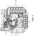
- FIG. 7 is a plan diagram of a substrate on which a driver circuit is mounted.
- FIG. 1 is an external perspective diagram showing a configuration example of the fan device 1 according to an embodiment.
- FIG. 2 is an exploded perspective diagram of a motor 2 and a fan 3 .
- the fan 3 is fastened to the motor 2 by a plurality of screws 10 .
- the screws are fastened to a rotor yoke 232 of the motor 2 from a front side of the fan 3 (a side opposite to a side facing the motor 2 ) through screw holes formed in a boss portion 31 serving as a central portion of the fan 3 .
- the number of screws and the types of fastening members are not particularly limited.
- the fan 3 includes the boss portion 31 that rotates integrally with a rotor 23 around an axial center of a shaft 21 , a plurality of (seven in this embodiment) blades 32 that project radially from an outer circumference of the boss portion 31 ; and a plurality of (seven in this embodiment) connecting members 33 that connect the adjacent blades 32 on a tip side.
- the boss portion 31 includes a disk-shaped disk portion 311 and a cylindrical peripheral wall portion 312 protruding from an outer edge of the disk portion 311 toward the motor 2 and having the plurality of blades 32 attached thereto.
- the disk portion 311 faces a connection wall 232 C of the rotor yoke 232 and the peripheral wall portion 312 surrounds the outer circumferential wall 232 A of the rotor yoke 232 .
- FIG. 3 is an exploded perspective diagram of a brushless motor 11 , a substrate 13 , and a driver case 15 .
- FIG. 4 is a perspective diagram showing a front surface side of a configuration of the motor 2 with the rotor yoke 232 removed.
- FIG. 5 is a longitudinal sectional diagram of the motor 2 .
- the motor 2 is a so-called “electromechanical integrated” electric motor including an outer rotor type brushless motor 11 and a substrate 13 on which a driver circuit 12 is mounted.
- the brushless motor 11 is supported by a motor bracket 14 .
- the brushless motor 11 is disposed on one side (front surface side) of the motor bracket 14 in a thickness direction.
- a driver case 15 is fastened to the other side (rear surface side) of the motor bracket 14 in the thickness direction by a plurality of screws. Thereby, an accommodation space for accommodating the substrate 13 is formed between a rear surface of the motor bracket 14 and the driver case 15 .
- the substrate 13 is disposed on a side opposite to components 21 - 24 of the brushless motor 11 (the rear surface side of the motor bracket 14 ) with the motor bracket 14 interposed therebetween.
- the motor bracket 14 and the driver case 15 are made of a material having high thermal conductivity (for example, a metal such as aluminum, iron, or stainless steel). Also, the motor bracket 14 and the driver case 15 may be black in order to increase heat absorption rate.
- a connector unit 16 in which two connectors to which an external harness is connected are integrated is attached to an end portion of the motor bracket 14 .
- the brushless motor 11 , the driver circuit 12 , and the connector unit 16 are electrically connected.
- the brushless motor 11 includes the shaft 21 ; a plurality of bearings 22 provided on an outer circumference of the shaft 21 ; the rotor 23 rotatably supported around the axial center of the shaft 21 via the bearings 22 ; and an annular stator 24 fixed at a predetermined interval from the rotor 23 in a radial direction.
- the shaft 21 is a fixed shaft fixed to the front surface side of the motor bracket 14 .
- an axial direction of the shaft 21 is simply referred to as the “axial direction”
- the radial direction around the axial center of the shaft 21 is simply referred to as the “radial direction”
- a circumferential direction around the axial center of the shaft 21 is simply referred to as the “circumferential direction”.
- the rotor 23 includes a plurality of permanent magnets 231 disposed at equal intervals in the circumferential direction so as to surround an outer circumference of the stator 24 , and the rotor yoke 232 that supports the plurality of permanent magnets 231 and is rotatably supported on the shaft 21 .
- the rotor yoke 232 is disposed on the front surface side of the motor bracket 14 so as to be concentric with the axial center of the shaft 21 . Moreover, the rotor yoke 232 is rotatably supported by the shaft 21 via the plurality of bearings 22 . Furthermore, the rotor yoke 232 includes an outer circumferential wall 232 A, an inner circumferential wall 232 B, and the connection wall 232 C.
- the outer circumferential wall 232 A has a cylindrical outer shape. Moreover, the outer circumferential wall 232 A is disposed outward of the stator 24 in the radial direction. Further, the outer circumferential wall 232 A supports the plurality of permanent magnets 231 with an inner circumferential surface. In other words, the plurality of permanent magnets 231 are fixed to an inner circumferential surface of the outer circumferential wall 232 A at predetermined intervals in the circumferential direction.
- the inner circumferential wall 232 B has a cylindrical outer shape. Moreover, the inner circumferential wall 232 B is disposed inward of the stator 24 in the radial direction. Further, the inner circumferential wall 232 B is rotatably supported by the shaft 21 via the plurality of bearings 22 .
- connection wall 232 C has a disk-shaped outer shape. Moreover, the connection wall 232 C connects axial ends of the outer circumferential wall 232 A and the inner circumferential wall 232 B. Furthermore, the connection wall 232 C is disposed on a side opposite to the motor bracket 14 with the stator 24 interposed therebetween. The connection wall 232 C is disposed opposite to the stator 24 with a predetermined interval in the axial direction.
- the stator 24 is accommodated in a space surrounded by the outer circumferential wall 232 A, the inner circumferential wall 232 B, the connection wall 232 C, and a front surface of the motor bracket 14 . Moreover, the stator 24 is fixed to the front surface side of the motor bracket 14 inward of the plurality of permanent magnets 231 in the radial direction. Furthermore, the stator 24 faces the plurality of permanent magnets 231 with a predetermined gap in the radial direction.
- the stator 24 includes a cylindrical stator core 241 , a stator insulator 242 mounted on both sides in the axial direction of a plurality of teeth projecting outward in the radial direction from the stator core 241 ; and conductive coils 243 wound on the stator insulator 242 .
- the stator 24 generates a magnetic field when a current flows through the coils 243 .
- the rotor yoke 232 rotates around the axial center of the shaft 21 due to the magnetic field generated by the coils 243 and the attractive force and repulsive force generated between the plurality of permanent magnets 231 .
- the motor 2 is disposed in the engine room with the shaft 21 directed in a traveling direction of a vehicle.
- the motor 2 is disposed in the engine room with the brushless motor 11 facing forward and the driver case 15 facing rearward.
- FIG. 6 is a schematic circuit diagram of a power system circuit 120 included in the driver circuit 12 .
- FIG. 7 is a plan diagram of the substrate 13 on which the driver circuit 12 is mounted.
- the driver circuit 12 controls generation of the magnetic field by the plurality of coils 243 .
- the driver circuit 12 is composed of a plurality of electronic components (e.g. transistor, diode, resistor, etc.) surface-mounted on a front surface of the substrate 13 facing the motor bracket 14 .
- the substrate 13 has a plate-like shape made of, for example, an aluminum alloy.
- the power system circuit 120 mainly includes three positive side transistors: 122 U, 122 V 122 W; three negative side transistors: 123 U, 123 V, 123 W; a motor control IC 124 ; and a fuse 125 (hereinafter, they may be referred to collectively as “power system components 121 - 125 ”).
- the electronic components that supply current to the coils 243 are not limited to the power system components 121 - 125 described above.
- Sources of the positive side transistors 122 U, 122 V, 122 W are connected in parallel to a positive pole of the power source 121 . Drains of the positive side transistors 122 U, 122 V, 122 W are connected to the coils 243 of the U phase, V phase, and W phase, respectively. Furthermore, gates of the positive side transistors 122 U, 122 V, 122 W are connected to the motor control IC 124 .
- Sources of the negative side transistors 123 U, 123 V, 123 W are connected to the coils 243 of the U phase, V phase and W phase, respectively. Moreover, drains of the negative side transistors 123 U, 123 V, 123 W are connected in parallel to a negative pole of the power source 121 . Furthermore, gates of the negative side transistors 123 U, 123 V, 123 W are connected to the motor control IC 124 .
- a wiring from the positive pole of the power source 121 to the coils 243 via the positive side transistors 122 U, 122 V, 122 W is a positive wiring having a positive potential.
- a wiring from the coils 243 to the negative pole of the power source 121 via the negative side transistors 123 U, 123 V, 123 W is a GND wiring having a ground potential.
- the motor control IC 124 controls ON and OFF of the transistors 122 U, 122 V, 122 W, 123 U, 123 V, 123 W (supply and cutoff of current to the coils 243 ) by controlling the application of voltage to the gate of each transistor 122 U, 122 V, 122 W, 123 U, 123 V, 123 W.
- the fuse 125 is disposed between the positive pole of the power source 121 and the positive side transistors 122 U, 122 V, 122 W, and cuts off the wiring when an overcurrent flows through the power system circuit 120 .
- the front surface of the substrate 13 includes regions 131 and 132 .
- the positive wiring and the power system components 121 - 125 are disposed in the region 131
- the GND wiring is disposed in the region 132 .
- the positive wiring and GND wiring described here include not only the wiring of the power system circuit 120 described with reference to FIG. 6 , but also the wiring of a control system (e.g. speed controller, speed converter, voltage controller, etc.)
- a mark • in FIG. 7 indicates a position on the substrate 13 overlapping the shaft 21 when the motor 2 is viewed from the axial direction of the shaft 21 (in other words, a position where the shaft 21 is extended in the axial direction).
- an extension of the shaft 21 overlaps the region 132 . That is, the GND wiring of the driver circuit 12 is mounted on the region 132 on the substrate 13 overlapping the shaft 21 when the motor 2 is viewed from the axial direction of the shaft 21 .
- the positive wiring and the electronic components of the driver circuit 12 are mounted outside a region on the substrate 13 overlapping the shaft 21 when the motor 2 is viewed from the axial direction of the shaft 21 .
- a dashed line in FIG. 7 indicates a position overlapping the outer circumference of the stator 24 when the motor 2 is viewed from the axial direction of the shaft 21 .
- the power system components 121 - 125 are mounted outside a region on the substrate 13 overlapping the stator 24 .
- the power system components 121 - 125 are in contact with the metal motor bracket 14 via an adhesive 17 . It is desirable that the adhesive 17 has high thermal conductivity.
- the GND wiring of the driver circuit 12 is mounted on the region on the substrate 13 overlapping the shaft 21 when the motor 2 is viewed from the axial direction of the shaft 21 .
- the portion of the driver circuit 12 having positive potential (typically, the positive wiring) is mounted outside the region on the substrate 13 overlapping the shaft 21 when the motor 2 is viewed from the axial direction of the shaft 21 .
- the region on the substrate 13 overlapping the shaft 21 may be left unmounted when the motor 2 is viewed from the axial direction of the shaft 21 , although from the viewpoint of improving the residual copper rate, the GND wiring is preferably mounted.
- the power system components 121 - 125 are mounted outside the region on the substrate 13 overlapping the stator 24 when the motor 2 is viewed from the axial direction of the shaft 21 .
- the thermal influence on the coils 243 can be reduced.
- the power system components 121 - 125 may be kept away from the shaft 21 , the influence of heat received from the shaft 21 on the power system components 121 - 125 can be reduced. Thereby, the life of the motor 2 is extended, contributing to the waste reduction.
- the fan device 1 is equipped in a vehicle driven by an engine
- the fan device 1 may be equipped in a vehicle driven by a motor, storage battery, fuel cell, or the like.
- an application of the fan device 1 an example of supplying cooling air to a radiator has been described, but the application of the fan device 1 is not limited thereto.
- an application of the motor 2 an example of a fan motor that rotationally drives the fan 3 has been described, but the application of the motor 2 is not limited thereto.
- the substrate made of aluminum alloy is applied has been described, but the substrate 13 may be a substrate made of resin such as glass epoxy resin.
- the disclosure has been described above. Moreover, the disclosure is not limited to the above embodiment, and includes various modifications.
- the above embodiment has been described in detail in order to explain the disclosure in an easy-to-understand manner, and is not necessarily limited to having all the configurations described.
- a part of the configuration of this embodiment may be replaced with the configuration of another embodiment, and it is also possible to add the configuration of another embodiment to the configuration of this embodiment.
Landscapes
- Engineering & Computer Science (AREA)
- Power Engineering (AREA)
- Mechanical Engineering (AREA)
- General Engineering & Computer Science (AREA)
- Microelectronics & Electronic Packaging (AREA)
- Motor Or Generator Frames (AREA)
- Connection Of Motors, Electrical Generators, Mechanical Devices, And The Like (AREA)
Abstract
A motor and a fan device are provided. The motor includes a motor bracket; a conductive shaft fixed to a front surface side of the motor bracket; a rotor rotatably supported on the shaft; a stator fixed to the front surface side of the motor bracket inside the rotor and wound with a plurality of coils for generating a magnetic field to rotate the rotor; a substrate, a front surface thereof mounted with a driver circuit for controlling magnetic field generation by the coils; and a driver case fixed to a rear surface side of the motor bracket and forming an accommodation space accommodating the substrate between itself and the motor bracket. A positive wiring of the driver circuit is mounted outside a region on the substrate overlapping the shaft when the motor is viewed from an axial direction of the shaft.
Description
This application claims the priority benefits of Japanese application no. 2022-041653, filed on Mar. 16, 2022. The entity of the above-mentioned patent application is hereby incorporated by reference herein and made a part of this specification.
The disclosure relates to a motor and a fan device equipped with the motor.
In recent years, efforts have been made to promote the Sustainable Development Goals (2030 Agenda for Sustainable Development, adopted at the United Nations Summit on Sep. 25, 2015, hereinafter referred to as “SDGs”). Along with this, techniques are known that aim to reduce waste and defective products in order to secure sustainable production and consumption patterns.
A so-called “electromechanical integrated” motor in which a driver circuit for driving the motor is integrated is known. In an electromechanical integrated motor, for example, a shaft, a rotor, and a stator are generally disposed on a front surface side of a motor bracket, and a substrate on which a driver circuit is mounted is disposed on a rear surface side of the motor bracket. Further, such a motor is equipped in an engine room of a vehicle, for example, as a motor that drives a cooling fan that supplies cooling air to a radiator (see Patent Literature 1: JP 2019-108872 A, for example).
In such an electromechanical integrated motor, if the shaft breaks through the motor bracket and contacts the substrate in the case of a vehicle collision, there is a problem that the driver circuit is short-circuited and an overcurrent flows.
The disclosure provides a technique for preventing an overcurrent from flowing even when a shaft contacts a substrate in an electromechanical integrated motor having a driver circuit integrated therein.
The disclosure provides: a motor, including: a motor bracket; a conductive shaft fixed to a front surface side of the motor bracket; a rotor rotatably supported on the shaft; a stator fixed to the front surface side of the motor bracket inside the rotor and wound with a plurality of coils for generating a magnetic field to rotate the rotor; a substrate, a front surface thereof mounted which a driver circuit for controlling magnetic field generation by the coils; and a driver case fixed to a rear surface side of the motor bracket and forming an accommodation space accommodating the substrate between itself and the motor bracket. A positive wiring of the driver circuit is mounted outside a region on the substrate overlapping the shaft when the motor is viewed from an axial direction of the shaft.
According to the disclosure, it is possible to prevent an overcurrent from flowing even when a shaft contacts a substrate in an electromechanical integrated motor having a driver circuit integrated therein. Problems, configurations, and effects other than those described above will be explained by the following description of the embodiments.
As one aspect of a fan device according to an embodiment of the disclosure, a fan device that is equipped in a vehicle such as an automobile and cools engine cooling water or the like flowing in a radiator will be described below.
(Overall Configuration of Fan Device 1)
First, an overall configuration of a fan device 1 will be described with reference to FIGS. 1 and 2 . FIG. 1 is an external perspective diagram showing a configuration example of the fan device 1 according to an embodiment. FIG. 2 is an exploded perspective diagram of a motor 2 and a fan 3.
As shown in FIGS. 1 and 2 , the fan device 1 includes the motor 2 which is a drive source, and the fan 3 which is rotationally driven by the motor 2 to generate cooling air. The fan device 1 is installed in an engine room, for example, such that the motor 2 is disposed on a rear side (the side facing an engine) and the fan 3 is disposed on a front side (the side facing a radiator).
The fan 3 is fastened to the motor 2 by a plurality of screws 10. The screws are fastened to a rotor yoke 232 of the motor 2 from a front side of the fan 3 (a side opposite to a side facing the motor 2) through screw holes formed in a boss portion 31 serving as a central portion of the fan 3. It is not always necessary to use the screws 10 as fastening members for fastening the fan 3 to the motor 2. As long as the fan 3 may be fastened to the motor 2, the number of screws and the types of fastening members are not particularly limited.
The fan 3 includes the boss portion 31 that rotates integrally with a rotor 23 around an axial center of a shaft 21, a plurality of (seven in this embodiment) blades 32 that project radially from an outer circumference of the boss portion 31; and a plurality of (seven in this embodiment) connecting members 33 that connect the adjacent blades 32 on a tip side.
The boss portion 31 includes a disk-shaped disk portion 311 and a cylindrical peripheral wall portion 312 protruding from an outer edge of the disk portion 311 toward the motor 2 and having the plurality of blades 32 attached thereto. When the fan 3 is attached to the motor 2, the disk portion 311 faces a connection wall 232C of the rotor yoke 232 and the peripheral wall portion 312 surrounds the outer circumferential wall 232A of the rotor yoke 232.
(Configuration of Motor 2)
Next, the configuration of the motor 2 will be described with reference to FIGS. 3 to 5 . FIG. 3 is an exploded perspective diagram of a brushless motor 11, a substrate 13, and a driver case 15. FIG. 4 is a perspective diagram showing a front surface side of a configuration of the motor 2 with the rotor yoke 232 removed. FIG. 5 is a longitudinal sectional diagram of the motor 2.
As shown in FIGS. 3 to 5 , the motor 2 is a so-called “electromechanical integrated” electric motor including an outer rotor type brushless motor 11 and a substrate 13 on which a driver circuit 12 is mounted.
The brushless motor 11 is supported by a motor bracket 14. The brushless motor 11 is disposed on one side (front surface side) of the motor bracket 14 in a thickness direction. A driver case 15 is fastened to the other side (rear surface side) of the motor bracket 14 in the thickness direction by a plurality of screws. Thereby, an accommodation space for accommodating the substrate 13 is formed between a rear surface of the motor bracket 14 and the driver case 15.
In other words, the substrate 13 is disposed on a side opposite to components 21-24 of the brushless motor 11 (the rear surface side of the motor bracket 14) with the motor bracket 14 interposed therebetween. The motor bracket 14 and the driver case 15 are made of a material having high thermal conductivity (for example, a metal such as aluminum, iron, or stainless steel). Also, the motor bracket 14 and the driver case 15 may be black in order to increase heat absorption rate.
A connector unit 16 in which two connectors to which an external harness is connected are integrated is attached to an end portion of the motor bracket 14. The brushless motor 11, the driver circuit 12, and the connector unit 16 are electrically connected.
As shown in FIGS. 3-5 , the brushless motor 11 includes the shaft 21; a plurality of bearings 22 provided on an outer circumference of the shaft 21; the rotor 23 rotatably supported around the axial center of the shaft 21 via the bearings 22; and an annular stator 24 fixed at a predetermined interval from the rotor 23 in a radial direction.
The shaft 21 is a fixed shaft fixed to the front surface side of the motor bracket 14. In the following description of components of the motor 2, an axial direction of the shaft 21 is simply referred to as the “axial direction”, the radial direction around the axial center of the shaft 21 is simply referred to as the “radial direction”, and a circumferential direction around the axial center of the shaft 21 is simply referred to as the “circumferential direction”.
The rotor 23 includes a plurality of permanent magnets 231 disposed at equal intervals in the circumferential direction so as to surround an outer circumference of the stator 24, and the rotor yoke 232 that supports the plurality of permanent magnets 231 and is rotatably supported on the shaft 21.
The rotor yoke 232 is disposed on the front surface side of the motor bracket 14 so as to be concentric with the axial center of the shaft 21. Moreover, the rotor yoke 232 is rotatably supported by the shaft 21 via the plurality of bearings 22. Furthermore, the rotor yoke 232 includes an outer circumferential wall 232A, an inner circumferential wall 232B, and the connection wall 232C.
The outer circumferential wall 232A has a cylindrical outer shape. Moreover, the outer circumferential wall 232A is disposed outward of the stator 24 in the radial direction. Further, the outer circumferential wall 232A supports the plurality of permanent magnets 231 with an inner circumferential surface. In other words, the plurality of permanent magnets 231 are fixed to an inner circumferential surface of the outer circumferential wall 232A at predetermined intervals in the circumferential direction.
The inner circumferential wall 232B has a cylindrical outer shape. Moreover, the inner circumferential wall 232B is disposed inward of the stator 24 in the radial direction. Further, the inner circumferential wall 232B is rotatably supported by the shaft 21 via the plurality of bearings 22.
The connection wall 232C has a disk-shaped outer shape. Moreover, the connection wall 232C connects axial ends of the outer circumferential wall 232A and the inner circumferential wall 232B. Furthermore, the connection wall 232C is disposed on a side opposite to the motor bracket 14 with the stator 24 interposed therebetween. The connection wall 232C is disposed opposite to the stator 24 with a predetermined interval in the axial direction.
The stator 24 is accommodated in a space surrounded by the outer circumferential wall 232A, the inner circumferential wall 232B, the connection wall 232C, and a front surface of the motor bracket 14. Moreover, the stator 24 is fixed to the front surface side of the motor bracket 14 inward of the plurality of permanent magnets 231 in the radial direction. Furthermore, the stator 24 faces the plurality of permanent magnets 231 with a predetermined gap in the radial direction.
The stator 24 includes a cylindrical stator core 241, a stator insulator 242 mounted on both sides in the axial direction of a plurality of teeth projecting outward in the radial direction from the stator core 241; and conductive coils 243 wound on the stator insulator 242.
The stator 24 generates a magnetic field when a current flows through the coils 243. The rotor yoke 232 rotates around the axial center of the shaft 21 due to the magnetic field generated by the coils 243 and the attractive force and repulsive force generated between the plurality of permanent magnets 231.
Moreover, the motor 2 is disposed in the engine room with the shaft 21 directed in a traveling direction of a vehicle. The motor 2 is disposed in the engine room with the brushless motor 11 facing forward and the driver case 15 facing rearward.
(Configuration of Driver Circuit 12)
As shown in FIG. 6 , to supply current from a power source 121 to the coils 243 of the brushless motor 11, the power system circuit 120 mainly includes three positive side transistors: 122U, 122 V 122W; three negative side transistors: 123U, 123V, 123W; a motor control IC 124; and a fuse 125 (hereinafter, they may be referred to collectively as “power system components 121-125”). Moreover, the electronic components that supply current to the coils 243 are not limited to the power system components 121-125 described above.
Sources of the positive side transistors 122U, 122V, 122W are connected in parallel to a positive pole of the power source 121. Drains of the positive side transistors 122U, 122V, 122W are connected to the coils 243 of the U phase, V phase, and W phase, respectively. Furthermore, gates of the positive side transistors 122U, 122V, 122W are connected to the motor control IC 124.
Sources of the negative side transistors 123U, 123V, 123W are connected to the coils 243 of the U phase, V phase and W phase, respectively. Moreover, drains of the negative side transistors 123U, 123V, 123W are connected in parallel to a negative pole of the power source 121. Furthermore, gates of the negative side transistors 123U, 123V, 123W are connected to the motor control IC 124.
In other words, a wiring from the positive pole of the power source 121 to the coils 243 via the positive side transistors 122U, 122V, 122W is a positive wiring having a positive potential. Also, a wiring from the coils 243 to the negative pole of the power source 121 via the negative side transistors 123U, 123V, 123W is a GND wiring having a ground potential.
The motor control IC 124 controls ON and OFF of the transistors 122U, 122V, 122W, 123U, 123V, 123W (supply and cutoff of current to the coils 243) by controlling the application of voltage to the gate of each transistor 122U, 122V, 122W, 123U, 123V, 123W. The fuse 125 is disposed between the positive pole of the power source 121 and the positive side transistors 122U, 122V, 122W, and cuts off the wiring when an overcurrent flows through the power system circuit 120.
As shown in FIG. 7 , the front surface of the substrate 13 includes regions 131 and 132. Among the wirings forming the driver circuit 12, the positive wiring and the power system components 121-125 are disposed in the region 131, and the GND wiring is disposed in the region 132. Moreover, the positive wiring and GND wiring described here include not only the wiring of the power system circuit 120 described with reference to FIG. 6 , but also the wiring of a control system (e.g. speed controller, speed converter, voltage controller, etc.)
A mark • in FIG. 7 indicates a position on the substrate 13 overlapping the shaft 21 when the motor 2 is viewed from the axial direction of the shaft 21 (in other words, a position where the shaft 21 is extended in the axial direction). As shown in FIG. 7 , an extension of the shaft 21 overlaps the region 132. That is, the GND wiring of the driver circuit 12 is mounted on the region 132 on the substrate 13 overlapping the shaft 21 when the motor 2 is viewed from the axial direction of the shaft 21. In other words, the positive wiring and the electronic components of the driver circuit 12 are mounted outside a region on the substrate 13 overlapping the shaft 21 when the motor 2 is viewed from the axial direction of the shaft 21.
A dashed line in FIG. 7 indicates a position overlapping the outer circumference of the stator 24 when the motor 2 is viewed from the axial direction of the shaft 21. The power system components 121-125 are mounted outside a region on the substrate 13 overlapping the stator 24.
Furthermore, as shown in FIG. 5 , the power system components 121-125 are in contact with the metal motor bracket 14 via an adhesive 17. It is desirable that the adhesive 17 has high thermal conductivity.
According to the above embodiment, for example, the following operational effects are obtained.
According to the above embodiment, the GND wiring of the driver circuit 12 is mounted on the region on the substrate 13 overlapping the shaft 21 when the motor 2 is viewed from the axial direction of the shaft 21. Thereby, even if the shaft 21 passes through the motor bracket 14 and contacts the substrate 13, only the shaft 21 and the GND wiring having the same potential come into contact with each other, thus overcurrent does not flow throughout the driver circuit 12. As a result, it is possible to prevent blowing of the fuse 125.
In order to prevent overcurrent from flowing through the driver circuit 12, it is only necessary to avoid the shaft 21 passing through the motor bracket 14 from coming into contact with the portion of the driver circuit 12 having positive potential. In other words, it is only necessary that the portion of the driver circuit 12 having positive potential (typically, the positive wiring) is mounted outside the region on the substrate 13 overlapping the shaft 21 when the motor 2 is viewed from the axial direction of the shaft 21. Here, the region on the substrate 13 overlapping the shaft 21 may be left unmounted when the motor 2 is viewed from the axial direction of the shaft 21, although from the viewpoint of improving the residual copper rate, the GND wiring is preferably mounted.
Further, according to the above embodiment, the power system components 121-125 are mounted outside the region on the substrate 13 overlapping the stator 24 when the motor 2 is viewed from the axial direction of the shaft 21. In this way, by keeping the power system components 121-125 that generate heat by themselves away from the coils 243, the thermal influence on the coils 243 can be reduced. Further, since the power system components 121-125 may be kept away from the shaft 21, the influence of heat received from the shaft 21 on the power system components 121-125 can be reduced. Thereby, the life of the motor 2 is extended, contributing to the waste reduction.
Furthermore, according to the above embodiment, since the power system components 121-125 are brought into contact with the metal motor bracket 14 via the adhesive 17, heat radiation effect is improved. In particular, when the fan 3 is driven by the motor 2, since the motor bracket 14 is cooled by the cooling air generated by the fan 3, the heat dissipation effect is further improved. Thereby, the life of the motor 2 is extended, contributing to the waste reduction.
In the above embodiment, an example in which the fan device 1 is equipped in a vehicle driven by an engine has been described, but the fan device 1 may be equipped in a vehicle driven by a motor, storage battery, fuel cell, or the like. Also, as an application of the fan device 1, an example of supplying cooling air to a radiator has been described, but the application of the fan device 1 is not limited thereto. Furthermore, in the embodiment, as an application of the motor 2, an example of a fan motor that rotationally drives the fan 3 has been described, but the application of the motor 2 is not limited thereto. Moreover, an example in which the substrate made of aluminum alloy is applied has been described, but the substrate 13 may be a substrate made of resin such as glass epoxy resin.
The embodiment of the disclosure has been described above. Moreover, the disclosure is not limited to the above embodiment, and includes various modifications. For example, the above embodiment has been described in detail in order to explain the disclosure in an easy-to-understand manner, and is not necessarily limited to having all the configurations described. Further, a part of the configuration of this embodiment may be replaced with the configuration of another embodiment, and it is also possible to add the configuration of another embodiment to the configuration of this embodiment. Furthermore, it is possible to add, delete, or replace a part of the configuration of this embodiment with another configuration.
Claims (12)
1. A motor, comprising:
a motor bracket;
a conductive shaft fixed to a front surface side of the motor bracket;
a rotor rotatably supported on the shaft;
a stator fixed to the front surface side of the motor bracket inside the rotor and wound with a plurality of coils for generating a magnetic field to rotate the rotor;
a substrate, a front surface thereof mounted which a driver circuit for controlling magnetic field generation by the coils;
a driver case fixed to a rear surface side of the motor bracket and forming an accommodation space accommodating the substrate between itself and the motor bracket,
wherein a positive wiring of the driver circuit is mounted outside a region on the substrate overlapping the shaft when the motor is viewed from an axial direction of the shaft.
2. The motor according to claim 1 ,
wherein a GND wiring of the driver circuit is mounted on the region on the substrate overlapping the shaft when the motor is viewed from the axial direction of the shaft.
3. The motor according to claim 1 ,
wherein a power system component of the driver current that supplies current to the coils is mounted outside a region on the substrate overlapping the stator when the motor is viewed from the axial direction of the shaft.
4. The motor according to claim 2 ,
wherein a power system component of the driver current that supplies current to the coils is mounted outside a region on the substrate overlapping the stator when the motor is viewed from the axial direction of the shaft.
5. The motor according to claim 3 ,
wherein the power system component is in contact with the motor bracket made of metal via an adhesive.
6. The motor according to claim 4 ,
wherein the power system component is in contact with the motor bracket made of metal via an adhesive.
7. A fan device, comprising:
the motor according to claim 1 ; and
a fan rotationally driven by the motor to generate cooling air.
8. A fan device, comprising:
the motor according to claim 2 ; and
a fan rotationally driven by the motor to generate cooling air.
9. A fan device, comprising:
the motor according to claim 3 ; and
a fan rotationally driven by the motor to generate cooling air.
10. A fan device, comprising:
the motor according to claim 4 ; and
a fan rotationally driven by the motor to generate cooling air.
11. A fan device, comprising:
the motor according to claim 5 ; and
a fan rotationally driven by the motor to generate cooling air.
12. A fan device, comprising:
the motor according to claim 6 ; and
a fan rotationally driven by the motor to generate cooling air.
Applications Claiming Priority (2)
| Application Number | Priority Date | Filing Date | Title |
|---|---|---|---|
| JP2022-041653 | 2022-03-16 | ||
| JP2022041653A JP2023136178A (en) | 2022-03-16 | 2022-03-16 | Motor and fan device |
Publications (2)
| Publication Number | Publication Date |
|---|---|
| US20230296103A1 US20230296103A1 (en) | 2023-09-21 |
| US12247571B2 true US12247571B2 (en) | 2025-03-11 |
Family
ID=87993720
Family Applications (1)
| Application Number | Title | Priority Date | Filing Date |
|---|---|---|---|
| US18/164,569 Active 2043-11-05 US12247571B2 (en) | 2022-03-16 | 2023-02-04 | Motor and fan device |
Country Status (3)
| Country | Link |
|---|---|
| US (1) | US12247571B2 (en) |
| JP (1) | JP2023136178A (en) |
| CN (1) | CN116780829A (en) |
Citations (4)
| Publication number | Priority date | Publication date | Assignee | Title |
|---|---|---|---|---|
| US20040084980A1 (en) * | 2002-10-28 | 2004-05-06 | Tadao Yamaguchi | Axial-air-gap brushless vibration motor containing drive circuit |
| US20060028077A1 (en) * | 2004-08-04 | 2006-02-09 | Tadao Yamaguchi | Flat vibration brushless motor |
| US20170008554A1 (en) * | 2014-02-14 | 2017-01-12 | Mitsubishi Electric Corporation | Rotating electric machine with a built-in control device and electric power assist steering system |
| US20190186335A1 (en) * | 2017-12-20 | 2019-06-20 | Toyota Jidosha Kabushiki Kaisha | Air blowing fan device |
Family Cites Families (8)
| Publication number | Priority date | Publication date | Assignee | Title |
|---|---|---|---|---|
| JPH1127959A (en) * | 1997-07-08 | 1999-01-29 | Toshiba Fa Syst Eng Kk | Inverter device |
| JP4545968B2 (en) * | 2001-02-26 | 2010-09-15 | ヤマハ発動機株式会社 | Wheel motor transmission |
| JP6079957B2 (en) * | 2012-12-10 | 2017-02-15 | 日本電産株式会社 | Motor and fan |
| US10759467B2 (en) * | 2015-09-18 | 2020-09-01 | Mitsubishi Electric Corporation | Integrated electric power steering apparatus |
| JP6720589B2 (en) * | 2016-03-09 | 2020-07-08 | 株式会社デンソー | motor |
| JP7141100B2 (en) * | 2018-10-24 | 2022-09-22 | 株式会社テージーケー | electric valve |
| JP2020076330A (en) * | 2018-11-05 | 2020-05-21 | 日本電産株式会社 | Blower device |
| JP7265386B2 (en) * | 2019-03-19 | 2023-04-26 | ミネベアミツミ株式会社 | centrifugal fan |
-
2022
- 2022-03-16 JP JP2022041653A patent/JP2023136178A/en active Pending
-
2023
- 2023-01-05 CN CN202310011788.5A patent/CN116780829A/en active Pending
- 2023-02-04 US US18/164,569 patent/US12247571B2/en active Active
Patent Citations (5)
| Publication number | Priority date | Publication date | Assignee | Title |
|---|---|---|---|---|
| US20040084980A1 (en) * | 2002-10-28 | 2004-05-06 | Tadao Yamaguchi | Axial-air-gap brushless vibration motor containing drive circuit |
| US20060028077A1 (en) * | 2004-08-04 | 2006-02-09 | Tadao Yamaguchi | Flat vibration brushless motor |
| US20170008554A1 (en) * | 2014-02-14 | 2017-01-12 | Mitsubishi Electric Corporation | Rotating electric machine with a built-in control device and electric power assist steering system |
| US20190186335A1 (en) * | 2017-12-20 | 2019-06-20 | Toyota Jidosha Kabushiki Kaisha | Air blowing fan device |
| JP2019108872A (en) | 2017-12-20 | 2019-07-04 | トヨタ自動車株式会社 | Air blowing fan |
Also Published As
| Publication number | Publication date |
|---|---|
| US20230296103A1 (en) | 2023-09-21 |
| CN116780829A (en) | 2023-09-19 |
| JP2023136178A (en) | 2023-09-29 |
Similar Documents
| Publication | Publication Date | Title |
|---|---|---|
| JP4851575B2 (en) | Controller-integrated rotating electrical machine | |
| JP5039171B2 (en) | Electric drive device and electric power steering device equipped with the electric drive device | |
| JP5542977B1 (en) | Rotating electric machine | |
| JP5373936B1 (en) | Controller-integrated rotating electrical machine | |
| JP4859950B2 (en) | Rotating electric machine | |
| JP2012245915A (en) | Control unit and drive apparatus using the same | |
| CN112653297B (en) | Motor device | |
| US20170317557A1 (en) | Controller Integrated Rotating Electrical Machine | |
| JP4861836B2 (en) | Electric fan device for vehicle for radiator cooling | |
| JP5796301B2 (en) | Motor and electric power steering device | |
| JP4116644B2 (en) | Controller-integrated rotating electrical machine | |
| US9570962B2 (en) | Controller-integrated rotating electrical machine | |
| US12247571B2 (en) | Motor and fan device | |
| US20050214144A1 (en) | Centrifugal Fan | |
| JP2003274606A (en) | Rotating electric machine | |
| JP5701346B2 (en) | Rotating electric machine | |
| JP7186843B1 (en) | Rotating electric machine | |
| JP2016226231A (en) | Rotating electric machine | |
| JP2005224044A (en) | Power generation dynamo-electric apparatus for vehicle | |
| JP2018191428A (en) | Controlling device built-in rotary electric machine | |
| US12249897B2 (en) | Motor and fan device | |
| US20250084857A1 (en) | Fan device | |
| JP2021118624A (en) | motor | |
| JP2005237137A (en) | Generator for vehicle | |
| JP7113945B1 (en) | Rotating electric machine |
Legal Events
| Date | Code | Title | Description |
|---|---|---|---|
| FEPP | Fee payment procedure |
Free format text: ENTITY STATUS SET TO UNDISCOUNTED (ORIGINAL EVENT CODE: BIG.); ENTITY STATUS OF PATENT OWNER: LARGE ENTITY |
|
| STPP | Information on status: patent application and granting procedure in general |
Free format text: DOCKETED NEW CASE - READY FOR EXAMINATION |
|
| STPP | Information on status: patent application and granting procedure in general |
Free format text: NOTICE OF ALLOWANCE MAILED -- APPLICATION RECEIVED IN OFFICE OF PUBLICATIONS |
|
| ZAAB | Notice of allowance mailed |
Free format text: ORIGINAL CODE: MN/=. |
|
| STPP | Information on status: patent application and granting procedure in general |
Free format text: PUBLICATIONS -- ISSUE FEE PAYMENT VERIFIED |
|
| STCF | Information on status: patent grant |
Free format text: PATENTED CASE |