US12241575B2 - Blind insert fluid connection module - Google Patents
Blind insert fluid connection module Download PDFInfo
- Publication number
- US12241575B2 US12241575B2 US18/395,635 US202318395635A US12241575B2 US 12241575 B2 US12241575 B2 US 12241575B2 US 202318395635 A US202318395635 A US 202318395635A US 12241575 B2 US12241575 B2 US 12241575B2
- Authority
- US
- United States
- Prior art keywords
- fluid
- connection module
- shaped elastic
- elastic sheets
- fluid connector
- Prior art date
- Legal status (The legal status is an assumption and is not a legal conclusion. Google has not performed a legal analysis and makes no representation as to the accuracy of the status listed.)
- Active
Links
- 239000012530 fluid Substances 0.000 title claims abstract description 133
- 238000006073 displacement reaction Methods 0.000 claims abstract description 12
- 238000003780 insertion Methods 0.000 description 8
- 230000037431 insertion Effects 0.000 description 8
- 238000001816 cooling Methods 0.000 description 3
- 230000017525 heat dissipation Effects 0.000 description 3
- 238000012986 modification Methods 0.000 description 2
- 230000004048 modification Effects 0.000 description 2
- XLYOFNOQVPJJNP-UHFFFAOYSA-N water Substances O XLYOFNOQVPJJNP-UHFFFAOYSA-N 0.000 description 2
- 230000000712 assembly Effects 0.000 description 1
- 238000000429 assembly Methods 0.000 description 1
- 230000003139 buffering effect Effects 0.000 description 1
- 239000012809 cooling fluid Substances 0.000 description 1
- 238000009434 installation Methods 0.000 description 1
Images


Classifications
-
- F—MECHANICAL ENGINEERING; LIGHTING; HEATING; WEAPONS; BLASTING
- F16—ENGINEERING ELEMENTS AND UNITS; GENERAL MEASURES FOR PRODUCING AND MAINTAINING EFFECTIVE FUNCTIONING OF MACHINES OR INSTALLATIONS; THERMAL INSULATION IN GENERAL
- F16L—PIPES; JOINTS OR FITTINGS FOR PIPES; SUPPORTS FOR PIPES, CABLES OR PROTECTIVE TUBING; MEANS FOR THERMAL INSULATION IN GENERAL
- F16L37/00—Couplings of the quick-acting type
-
- H—ELECTRICITY
- H05—ELECTRIC TECHNIQUES NOT OTHERWISE PROVIDED FOR
- H05K—PRINTED CIRCUITS; CASINGS OR CONSTRUCTIONAL DETAILS OF ELECTRIC APPARATUS; MANUFACTURE OF ASSEMBLAGES OF ELECTRICAL COMPONENTS
- H05K7/00—Constructional details common to different types of electric apparatus
- H05K7/14—Mounting supporting structure in casing or on frame or rack
- H05K7/1485—Servers; Data center rooms, e.g. 19-inch computer racks
- H05K7/1487—Blade assemblies, e.g. blade cases or inner arrangements within a blade
-
- H—ELECTRICITY
- H05—ELECTRIC TECHNIQUES NOT OTHERWISE PROVIDED FOR
- H05K—PRINTED CIRCUITS; CASINGS OR CONSTRUCTIONAL DETAILS OF ELECTRIC APPARATUS; MANUFACTURE OF ASSEMBLAGES OF ELECTRICAL COMPONENTS
- H05K7/00—Constructional details common to different types of electric apparatus
- H05K7/14—Mounting supporting structure in casing or on frame or rack
- H05K7/1485—Servers; Data center rooms, e.g. 19-inch computer racks
- H05K7/1488—Cabinets therefor, e.g. chassis or racks or mechanical interfaces between blades and support structures
- H05K7/1489—Cabinets therefor, e.g. chassis or racks or mechanical interfaces between blades and support structures characterized by the mounting of blades therein, e.g. brackets, rails, trays
-
- H—ELECTRICITY
- H05—ELECTRIC TECHNIQUES NOT OTHERWISE PROVIDED FOR
- H05K—PRINTED CIRCUITS; CASINGS OR CONSTRUCTIONAL DETAILS OF ELECTRIC APPARATUS; MANUFACTURE OF ASSEMBLAGES OF ELECTRICAL COMPONENTS
- H05K7/00—Constructional details common to different types of electric apparatus
- H05K7/20—Modifications to facilitate cooling, ventilating, or heating
- H05K7/20218—Modifications to facilitate cooling, ventilating, or heating using a liquid coolant without phase change in electronic enclosures
- H05K7/20272—Accessories for moving fluid, for expanding fluid, for connecting fluid conduits, for distributing fluid, for removing gas or for preventing leakage, e.g. pumps, tanks or manifolds
-
- H—ELECTRICITY
- H05—ELECTRIC TECHNIQUES NOT OTHERWISE PROVIDED FOR
- H05K—PRINTED CIRCUITS; CASINGS OR CONSTRUCTIONAL DETAILS OF ELECTRIC APPARATUS; MANUFACTURE OF ASSEMBLAGES OF ELECTRICAL COMPONENTS
- H05K7/00—Constructional details common to different types of electric apparatus
- H05K7/20—Modifications to facilitate cooling, ventilating, or heating
- H05K7/20709—Modifications to facilitate cooling, ventilating, or heating for server racks or cabinets; for data centers, e.g. 19-inch computer racks
- H05K7/20763—Liquid cooling without phase change
- H05K7/20781—Liquid cooling without phase change within cabinets for removing heat from server blades
Definitions
- the present disclosure relates to a fluid connection module, and more particularly to a blind insert fluid connection module.
- Computer servers provide their powerful computing power through the network, so that they can complete a large amount of work in a short time and provide services for a large number of users.
- Conventional servers are usually densely installed on racks, which are convenient for centralized installation in air-conditioned machine rooms.
- the present disclosure provides a blind insert fluid connection module to deal with the needs of the prior art problems.
- a blind insert fluid connection module includes a first fluid connector on a first assembly and a second fluid connector on a second assembly.
- the second fluid connector is configured to engage the first fluid connector to form a fluid channel in a first direction.
- the second fluid connector includes a main body, a fastening member and a guide structure on the main body, and a cushioning resilient member.
- the second fluid connector is fixed to the guide structure.
- the cushioning resilient member is connected to the guide structure and configured to provide a buffer displacement of the second fluid connector in a second direction when the first and second fluid connectors are joined, wherein an included angle is formed between the second direction and the first direction.
- a blind insert fluid connection module includes a first fluid connector on a first assembly and a second fluid connector on a second assembly.
- the second fluid connector is configured to engage the first fluid connector to form a fluid channel in a first direction.
- the second fluid connector includes a main body, a fastening member and a guide structure on the main body, and a cushioning resilient member.
- the second fluid connector is movably connected with the guide structure.
- the cushioning resilient member is connected to the guide structure and configured to provide a buffer displacement of the second fluid connector in a second direction when the first and second fluid connectors are joined, wherein an included angle is formed between the second direction and the first direction.
- a blind insert fluid connection module includes a first fluid connector on a first assembly and a second fluid connector on a second assembly.
- the second fluid connector is configured to engage the first fluid connector to form a fluid channel in a first direction.
- the second fluid connector includes a main body and a fastening member and a guide structure on the main body.
- the guide structure includes an outer bracket fixed to the fastening member, an inner ring configured to secure the second fluid connector and a plurality of cushioning resilient pieces.
- the cushioning resilient pieces are interconnected between the inner ring and the outer bracket and configured to provide a buffer displacement of the second fluid connector in a second direction when the first and second fluid connectors are joined, wherein an included angle is formed between the second direction and the first direction.
- the first assembly has a positioning column of a polygonal cross section
- the guide structure has a positioning hole of the polygonal cross section configured to be inserted by the positioning column such that the first and second fluid connectors are guided to be joined.
- the first assembly has a positioning plate of an arc-line section, a curved-line section, a straight-line section or a bent-line section
- the guide structure has a positioning slot of the arc-line section, the curved-line section, the straight-line section or the bent-line section, configured to be inserted by the positioning plate such that the first and second fluid connectors are guided to be joined.
- the first assembly has at least two positioning pins
- the guide structure has at least two positioning holes configured to be inserted by the at least two positioning pins such that the first and second fluid connectors are guided to be joined.
- the first assembly is a server rack
- the second assembly is a server computing unit
- the cushioning resilient member has a spiral spring surrounding the second fluid connector and in contact with the fastening member.
- the blind insert fluid connection module further includes a fluid tube coupled to the second fluid connector.
- the guide structure includes arc-shaped buffer pieces for positioning the second fluid connector.
- the cushioning resilient pieces are wave-shaped elastic sheets extending radially from the inner ring to the outer bracket.
- the blind insert fluid connection module disclosed herein utilizes a positioning column, positioning plates, or positioning holes or slots to guide the first and second fluid connectors to a predetermined position, and utilizes a cushioning resilient member, arc-shaped buffer pieces, or cushioning resilient pieces to provide a buffer displacement when the first and second fluid connectors are engaged, so as to increase the margin of error during blind insertion.
- FIG. 1 illustrates a perspective view of a computer server assembly according to one embodiment of the present disclosure
- FIG. 2 illustrates an enlarged view of a portion of the computer server assembly in FIG. 1 ;
- FIGS. 3 , 4 illustrate perspective views of a blind insert fluid connection module according to a first embodiment of the present disclosure
- FIGS. 5 , 6 illustrate perspective views of a blind insert fluid connection module according to a second embodiment of the present disclosure
- FIGS. 7 , 8 illustrate perspective views of a blind insert fluid connection module according to a third embodiment of the present disclosure
- FIGS. 9 , 10 illustrate perspective views of a blind insert fluid connection module according to a fourth embodiment of the present disclosure.
- FIGS. 11 , 12 illustrate perspective views of a blind insert fluid connection module according to a fifth embodiment of the present disclosure.
- FIG. 1 illustrates a perspective view of a computer server 100 assembly according to one embodiment of the present disclosure
- FIG. 2 illustrates an enlarged view of a portion of the computer server assembly in FIG. 1
- the computer server assembly 100 includes a server rack 102 and a plurality of server computing units 110 that are inserted within rails of the server rack 102 such that several computer server assemblies 100 can be densely installed in air-conditioned machine rooms.
- the server rack 102 may be equipped with at least two fluid channel posts 104 on which first fluid connectors 106 are installed.
- Each server computing unit 110 may be equipped with two second fluid connectors 112 configured to engage the first fluid connector 106 to form fluid channels such that cooling fluids can be circulated in the server computing unit 110 in operation to achieve the purpose of cooling and heat dissipation.
- the blind insert fluid connection module may include the first fluid connectors 106 in a first assembly and the second fluid connector 112 in a second assembly.
- the first assembly may be the fluid channel post 104 of the server rack 102 (referring to FIG. 1 ) while the second assembly may be the server computing unit 110 (referring to FIG. 1 ).
- the second fluid connector 112 is configured to engage the first fluid connector 106 to form a fluid channel in a first direction.
- a fastening member 111 is located on a main body 110 a of the server computing unit 110 (referring to FIG. 1 ) such that the second fluid connector 112 can be installed on the fastening member 111 .
- a guide structure 114 is installed on the main body 110 a and movable within the fastening member 111 , and the second fluid connector 112 is fixed to the guide structure 114 such that these two members can be movable together and simultaneously.
- a spiral spring 116 surrounding the second fluid connector 112 as a cushioning resilient member, which is connected to the guide structure 114 and in contact with an inner wall of the fastening member 111 .
- the spiral spring 116 is configured to provide a buffer displacement (e.g., to meet an error margin during blind insertion) of the second fluid connector 112 along a second direction D 2 when the first and second fluid connectors are joined.
- An included angle is formed between the second direction D 2 and the first direction D 1 , or the second direction D 2 is nonparallel to the first direction D 1 .
- FIG. 4 merely illustrates examples of the second directions D 2 , but not being limited thereto.
- the fluid channel post 104 has a positioning column 108 of a triangular cross section while the guide structure 114 has a positioning hole 114 a of the same triangular cross section configured to be inserted by the positioning column 108 such that the first and second fluid connectors are guided to be joined, but not being limited thereto.
- the fluid channel post 104 may also have a positioning column with a quadrangular, pentagonal, or other polygonal cross section
- the guide structure 114 may also have a positioning hole with the same quadrangular, pentagonal, or other polygonal cross section for the positioning column to insert.
- a leading end of the positioning column 108 may also have a taper end 108 a , so as to increase the margin of error during blind insertion.
- the main body 110 a may have an opening 111 b to expose the second fluid connector 112 and the positioning hole 114 a , and an inner diameter of the opening 111 b is slight greater than an outer diameter of the second fluid connector 112 such that the second fluid connector 112 may have a buffer displacement in the second direction D 2 .
- the second fluid connector 112 is connected to a fluid tube 113 through an opening 111 a of the fastening member 111 , thereby being connected to an external water-cooled heat dissipation system.
- An inner diameter of the opening 111 a is slightly larger than an outer diameter of the fluid tube 113 , so that the fluid tube 113 can have a space for buffering displacement.
- FIGS. 5 , 6 illustrate perspective views of a blind insert fluid connection module according to a second embodiment of the present disclosure.
- the second embodiment differs from the first embodiment mainly in the guide positioning mechanism.
- the fluid channel post 104 may have a positioning plate 107 of a bent-line cross section (e.g., a L-shaped cross section in the drawings) while the guide structure 114 may have a positioning slot 114 b of the same bent-line cross section configured to be inserted by the positioning plate 107 such that the first and second fluid connectors are guided to be joined, but not being limited thereto.
- the fluid channel post 104 may also have a positioning plate of an arc-line cross section, a curved-line cross section or a straight-line cross section while the guide structure 114 may have a positioning slot of the same arc-line cross section, curved-line cross section or straight-line cross section configured to be inserted by the positioning plate 107 .
- a leading edge of the positioning plate 107 may also have a taper edge 107 a so as to increase the margin of error during blind insertion.
- FIGS. 7 , 8 illustrate perspective views of a blind insert fluid connection module according to a third embodiment of the present disclosure.
- the third embodiment differs from the first embodiment mainly in the guide positioning mechanism.
- the fluid channel post 104 may have at least two positioning columns 109 while the guide structure 114 may have at least two positioning holes 114 c configured to be inserted by the at least two positioning columns 109 such that the first and second fluid connectors are guided to be joined.
- a leading end of each positioning column 109 may also have a taper end 109 a so as to increase the margin of error during blind insertion.
- the first fluid connector 106 is positioned between the two positioning columns 109 while the second fluid connectors 112 is positioned between two positioning holes 114 c , but not being limited thereto.
- FIGS. 9 , 10 illustrate two perspective views of a blind insert fluid connection module according to a fourth embodiment of the present disclosure, wherein FIG. 10 illustrates the blind insert fluid connection module with the main body 110 a removed.
- the fourth embodiment differs from the previous embodiments mainly in the guide positioning mechanism.
- the guide structure 117 is installed on the main body 110 a and fixed within the fastening member 111 such that the guide structure 117 is unmovable relative to the fastening member 111 .
- the guide structure 117 includes arc-shaped buffer pieces 117 a (e.g., 4 pieces) for positioning the second fluid connector 112 therebetween such that the second fluid connector 112 is movably connected within the guide structure 117 .
- Each arc-shaped buffer piece 117 a has two opposite ends connected to two immediately-adjacent corners of the rectangular guide structure 117 .
- This embodiment also utilizes the spiral spring 116 surrounding the second fluid connector 112 as a cushioning resilient member.
- Both the arc-shaped buffer pieces 117 a and the spiral spring 116 are configured to provide a buffer displacement (e.g., to meet an error margin during blind insertion) of the second fluid connector 112 along a second direction D 2 when the first and second fluid connectors are joined.
- An included angle is formed between the second direction D 2 and the first direction D 1 , or the second direction D 2 is nonparallel to the first direction D 1 .
- FIG. 9 merely illustrates examples of the second directions D 2 , but not being limited thereto.
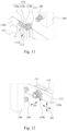
- FIGS. 11 , 12 illustrate perspective views of a blind insert fluid connection module according to a fifth embodiment of the present disclosure.
- the fifth embodiment differs from the fourth embodiment mainly in the guide positioning mechanism.
- the guide structure 118 is installed on the main body 110 a and positioned within the fastening member 111 .
- the guide structure 118 includes an outer bracket 118 a which is fixed within the fastening member 111 such that the outer bracket 118 a is unmovable relative to the fastening member 111 .
- the guide structure 118 further includes an inner ring 118 b configured to secure the second fluid connector 112 within.
- FIG. 12 merely illustrates examples of the second directions D 2 , but not being limited thereto.
- these cushioning resilient pieces 118 c are wave-shaped elastic sheets extending radially from the inner ring 118 b to the outer bracket 118 a , but not being limited thereto.
- a single positioning plate 107 mates with a single positioning slot 114 b as a guide mechanism, or a single positioning column 108 of a polygonal cross section mates with a single positioning hole 114 a as a guide mechanism, which can achieve a rotational positioning of two planes and a smooth engagement for the first and second fluid connectors.
- the blind insert fluid connection module disclosed herein utilizes a positioning column, positioning plates, or positioning holes or slots to guide the first and second fluid connectors to a predetermined position, and utilizes a cushioning resilient member, arc-shaped buffer pieces, or cushioning resilient pieces to provide a buffer displacement when the first and second fluid connectors are engaged, so as to increase the margin of error during blind insertion.
Landscapes
- Engineering & Computer Science (AREA)
- Microelectronics & Electronic Packaging (AREA)
- General Engineering & Computer Science (AREA)
- Computer Hardware Design (AREA)
- Physics & Mathematics (AREA)
- Thermal Sciences (AREA)
- Mechanical Engineering (AREA)
- Details Of Connecting Devices For Male And Female Coupling (AREA)
- Quick-Acting Or Multi-Walled Pipe Joints (AREA)
Abstract
Description
Claims (9)
Priority Applications (1)
| Application Number | Priority Date | Filing Date | Title |
|---|---|---|---|
| US18/395,635 US12241575B2 (en) | 2020-05-08 | 2023-12-25 | Blind insert fluid connection module |
Applications Claiming Priority (4)
| Application Number | Priority Date | Filing Date | Title |
|---|---|---|---|
| CN202010382907.4 | 2020-05-08 | ||
| CN202010382907.4A CN113631012B (en) | 2020-05-08 | 2020-05-08 | Blind-mate fluid connection modules |
| US17/170,842 US11898674B2 (en) | 2020-05-08 | 2021-02-08 | Blind insert fluid connection module |
| US18/395,635 US12241575B2 (en) | 2020-05-08 | 2023-12-25 | Blind insert fluid connection module |
Related Parent Applications (1)
| Application Number | Title | Priority Date | Filing Date |
|---|---|---|---|
| US17/170,842 Division US11898674B2 (en) | 2020-05-08 | 2021-02-08 | Blind insert fluid connection module |
Publications (2)
| Publication Number | Publication Date |
|---|---|
| US20240125417A1 US20240125417A1 (en) | 2024-04-18 |
| US12241575B2 true US12241575B2 (en) | 2025-03-04 |
Family
ID=78377253
Family Applications (2)
| Application Number | Title | Priority Date | Filing Date |
|---|---|---|---|
| US17/170,842 Active 2041-10-21 US11898674B2 (en) | 2020-05-08 | 2021-02-08 | Blind insert fluid connection module |
| US18/395,635 Active US12241575B2 (en) | 2020-05-08 | 2023-12-25 | Blind insert fluid connection module |
Family Applications Before (1)
| Application Number | Title | Priority Date | Filing Date |
|---|---|---|---|
| US17/170,842 Active 2041-10-21 US11898674B2 (en) | 2020-05-08 | 2021-02-08 | Blind insert fluid connection module |
Country Status (2)
| Country | Link |
|---|---|
| US (2) | US11898674B2 (en) |
| CN (1) | CN113631012B (en) |
Families Citing this family (6)
| Publication number | Priority date | Publication date | Assignee | Title |
|---|---|---|---|---|
| US12000514B2 (en) * | 2021-06-28 | 2024-06-04 | Microsoft Technology Licensing, Llc | Systems and methods for a floating quick disconnect in liquid cooling |
| US11997831B2 (en) * | 2021-12-21 | 2024-05-28 | Baidu Usa Llc | Connector alignment design for servers |
| CN117998804A (en) * | 2022-10-27 | 2024-05-07 | 富联精密电子(天津)有限公司 | Manifold, cabinet and data center cooling system |
| DE102022131170B4 (en) * | 2022-11-24 | 2025-01-09 | Ads-tec Energy GmbH | Fluid guiding device for guiding a fluid in a charging station and charging station with such a fluid guiding device |
| US12477686B2 (en) * | 2024-01-31 | 2025-11-18 | Dell Products L.P. | Liquid cooling bench clip |
| TWI866775B (en) | 2024-02-06 | 2024-12-11 | 富世達股份有限公司 | Floating joint and retainer connection structure |
Citations (24)
| Publication number | Priority date | Publication date | Assignee | Title |
|---|---|---|---|---|
| US2841419A (en) * | 1955-11-07 | 1958-07-01 | Orenda Engines Ltd | Flexible inner to outer pipe coupling with plural seals |
| AT324957B (en) * | 1974-06-11 | 1975-09-25 | Huber & Suhner A G Kabel Kauts | FLOW FITTING, IN PARTICULAR FOR SANITARY INSTALLATIONS |
| US20040074541A1 (en) | 2002-07-04 | 2004-04-22 | Andrew Sharpe | Flow connector |
| US20070274043A1 (en) | 2006-05-26 | 2007-11-29 | Younes Shabany | Liquid-Air Hybrid Cooling in Electronics Equipment |
| US20090322072A1 (en) | 2008-06-30 | 2009-12-31 | Staubli Faverges | Connection assembly and method of connecting such an assembly |
| CN103166051A (en) | 2011-12-14 | 2013-06-19 | 李立国 | Connector of power battery boxes of electric automobiles |
| CN204088751U (en) | 2014-09-29 | 2015-01-07 | Tcl集团股份有限公司 | A kind of blindmate guiding protecting seat of connector |
| CN104641161A (en) | 2012-05-25 | 2015-05-20 | 阿塞泰克丹麦公司 | Fluid connector for a cooling system |
| CN204424601U (en) | 2015-02-13 | 2015-06-24 | 常州市新盛电器有限公司 | Female cluster radio connector |
| US20160066480A1 (en) | 2014-08-29 | 2016-03-03 | International Business Machines Corporation | Blind docking apparatus to enable liquid cooling in compute nodes |
| CN107039845A (en) | 2017-04-13 | 2017-08-11 | 北京机械设备研究所 | Device in a kind of spacing time based on micro- rectangle floating blind plugging connector |
| US20170257980A1 (en) | 2016-03-07 | 2017-09-07 | Fujitsu Limited | Fitting assembly and electronic device |
| US20180242478A1 (en) | 2017-02-21 | 2018-08-23 | Baidu Usa Llc | Modular self-aligning liquid heat removal coupling system for electronic racks |
| US20180303007A1 (en) | 2017-04-18 | 2018-10-18 | Baidu Usa Llc | Modular quick-release liquid heat removal coupling system for electronic racks |
| CN109058629A (en) | 2018-10-17 | 2018-12-21 | 万硕(成都)航空科技有限公司 | Can plug with pressure blindmate fluid connector |
| US10164373B1 (en) | 2013-03-15 | 2018-12-25 | Koolance, Inc. | Automatic engagement system for liquid or power connections |
| CN109296861A (en) | 2018-11-02 | 2019-02-01 | 中国船舶重工集团公司第七二三研究所 | A kind of blindmate floating fluid connector |
| US20190045652A1 (en) | 2017-08-04 | 2019-02-07 | Fujitsu Limited | Information processing apparatus |
| KR101969079B1 (en) | 2018-04-26 | 2019-08-13 | 주식회사 도헌 | Ceiling plumbing cradle of double earthquake resistant structure |
| US10701838B1 (en) | 2019-03-25 | 2020-06-30 | Amazon Technologies, Inc. | Self-installing connections for rack liquid cooling |
| US10704983B1 (en) | 2019-09-05 | 2020-07-07 | Inventec (Pudong) Technology Corporation | Server |
| US20200260608A1 (en) | 2019-02-13 | 2020-08-13 | Ovh | Rack adapted for receiving a component, system including the rack and the component and method of delivering power to a component mounted in a rack |
| US10791654B2 (en) | 2018-07-17 | 2020-09-29 | Raytheon Company | Multi-purpose coolant interface |
| US20210212232A1 (en) * | 2020-01-08 | 2021-07-08 | Hongfujin Precision Electronics(Tianjin)Co.,Ltd. | Server |
Family Cites Families (1)
| Publication number | Priority date | Publication date | Assignee | Title |
|---|---|---|---|---|
| TWI743776B (en) * | 2020-05-08 | 2021-10-21 | 台達電子工業股份有限公司 | Blind insert fluid connection module |
-
2020
- 2020-05-08 CN CN202010382907.4A patent/CN113631012B/en active Active
-
2021
- 2021-02-08 US US17/170,842 patent/US11898674B2/en active Active
-
2023
- 2023-12-25 US US18/395,635 patent/US12241575B2/en active Active
Patent Citations (25)
| Publication number | Priority date | Publication date | Assignee | Title |
|---|---|---|---|---|
| US2841419A (en) * | 1955-11-07 | 1958-07-01 | Orenda Engines Ltd | Flexible inner to outer pipe coupling with plural seals |
| AT324957B (en) * | 1974-06-11 | 1975-09-25 | Huber & Suhner A G Kabel Kauts | FLOW FITTING, IN PARTICULAR FOR SANITARY INSTALLATIONS |
| US20040074541A1 (en) | 2002-07-04 | 2004-04-22 | Andrew Sharpe | Flow connector |
| US20070274043A1 (en) | 2006-05-26 | 2007-11-29 | Younes Shabany | Liquid-Air Hybrid Cooling in Electronics Equipment |
| US20090322072A1 (en) | 2008-06-30 | 2009-12-31 | Staubli Faverges | Connection assembly and method of connecting such an assembly |
| CN101619790A (en) | 2008-06-30 | 2010-01-06 | 施托布利法韦日公司 | Connection unit and method for connecting such a unit |
| CN103166051A (en) | 2011-12-14 | 2013-06-19 | 李立国 | Connector of power battery boxes of electric automobiles |
| CN104641161A (en) | 2012-05-25 | 2015-05-20 | 阿塞泰克丹麦公司 | Fluid connector for a cooling system |
| US10164373B1 (en) | 2013-03-15 | 2018-12-25 | Koolance, Inc. | Automatic engagement system for liquid or power connections |
| US20160066480A1 (en) | 2014-08-29 | 2016-03-03 | International Business Machines Corporation | Blind docking apparatus to enable liquid cooling in compute nodes |
| CN204088751U (en) | 2014-09-29 | 2015-01-07 | Tcl集团股份有限公司 | A kind of blindmate guiding protecting seat of connector |
| CN204424601U (en) | 2015-02-13 | 2015-06-24 | 常州市新盛电器有限公司 | Female cluster radio connector |
| US20170257980A1 (en) | 2016-03-07 | 2017-09-07 | Fujitsu Limited | Fitting assembly and electronic device |
| US20180242478A1 (en) | 2017-02-21 | 2018-08-23 | Baidu Usa Llc | Modular self-aligning liquid heat removal coupling system for electronic racks |
| CN107039845A (en) | 2017-04-13 | 2017-08-11 | 北京机械设备研究所 | Device in a kind of spacing time based on micro- rectangle floating blind plugging connector |
| US20180303007A1 (en) | 2017-04-18 | 2018-10-18 | Baidu Usa Llc | Modular quick-release liquid heat removal coupling system for electronic racks |
| US20190045652A1 (en) | 2017-08-04 | 2019-02-07 | Fujitsu Limited | Information processing apparatus |
| KR101969079B1 (en) | 2018-04-26 | 2019-08-13 | 주식회사 도헌 | Ceiling plumbing cradle of double earthquake resistant structure |
| US10791654B2 (en) | 2018-07-17 | 2020-09-29 | Raytheon Company | Multi-purpose coolant interface |
| CN109058629A (en) | 2018-10-17 | 2018-12-21 | 万硕(成都)航空科技有限公司 | Can plug with pressure blindmate fluid connector |
| CN109296861A (en) | 2018-11-02 | 2019-02-01 | 中国船舶重工集团公司第七二三研究所 | A kind of blindmate floating fluid connector |
| US20200260608A1 (en) | 2019-02-13 | 2020-08-13 | Ovh | Rack adapted for receiving a component, system including the rack and the component and method of delivering power to a component mounted in a rack |
| US10701838B1 (en) | 2019-03-25 | 2020-06-30 | Amazon Technologies, Inc. | Self-installing connections for rack liquid cooling |
| US10704983B1 (en) | 2019-09-05 | 2020-07-07 | Inventec (Pudong) Technology Corporation | Server |
| US20210212232A1 (en) * | 2020-01-08 | 2021-07-08 | Hongfujin Precision Electronics(Tianjin)Co.,Ltd. | Server |
Also Published As
| Publication number | Publication date |
|---|---|
| CN113631012B (en) | 2024-11-22 |
| US20210348706A1 (en) | 2021-11-11 |
| CN113631012A (en) | 2021-11-09 |
| US11898674B2 (en) | 2024-02-13 |
| US20240125417A1 (en) | 2024-04-18 |
Similar Documents
| Publication | Publication Date | Title |
|---|---|---|
| US12241575B2 (en) | Blind insert fluid connection module | |
| CN111142625B (en) | Rack Sets and Servers | |
| US6230541B1 (en) | Cardcage for circuit cards | |
| US6619766B1 (en) | Device mounting and retention assembly | |
| US7145776B2 (en) | Midplane-less data storage enclosure | |
| US8075248B2 (en) | Fan assembly | |
| JPH0530247B2 (en) | ||
| US5818696A (en) | Mounting panel for assemblies | |
| US9084340B2 (en) | Electronic device unit and electronic device | |
| TWI743776B (en) | Blind insert fluid connection module | |
| US20220087046A1 (en) | Modularized front window of a server system | |
| US6698079B1 (en) | Cardcage for circuit cards | |
| US20120320519A1 (en) | Storage device assembly | |
| TW202404217A (en) | Cable bracket for stacked hbas with bracket-mounted connectors | |
| CN108594969B (en) | Electronic equipment and switching device thereof | |
| CN102200808A (en) | Storage device fixing mechanism | |
| US6199839B1 (en) | Vibration dampening mechanism | |
| JP2003142854A (en) | Guide structure for inserting printed circuit cards at close internal | |
| US11672099B2 (en) | System level structure for blind mating connections | |
| CN110147144A (en) | Case and host comprising said case | |
| CN101206508B (en) | Frame structure of digital data storage device | |
| TWI872978B (en) | Thermal exchange device and power supply system applying the same | |
| CN223230119U (en) | Main shell, NAS and disk array cabinet | |
| CN221406429U (en) | Bracket assembly and electronic equipment | |
| US20250224053A1 (en) | Floating connector for liquid cooling device |
Legal Events
| Date | Code | Title | Description |
|---|---|---|---|
| AS | Assignment |
Owner name: DELTA ELECTRONICS, INC., TAIWAN Free format text: ASSIGNMENT OF ASSIGNORS INTEREST;ASSIGNORS:YANG, MING-TANG;SHEN, TENG-CHIAO;REEL/FRAME:065949/0125 Effective date: 20210205 |
|
| FEPP | Fee payment procedure |
Free format text: ENTITY STATUS SET TO UNDISCOUNTED (ORIGINAL EVENT CODE: BIG.); ENTITY STATUS OF PATENT OWNER: LARGE ENTITY |
|
| STPP | Information on status: patent application and granting procedure in general |
Free format text: DOCKETED NEW CASE - READY FOR EXAMINATION |
|
| STPP | Information on status: patent application and granting procedure in general |
Free format text: NON FINAL ACTION MAILED |
|
| STPP | Information on status: patent application and granting procedure in general |
Free format text: RESPONSE TO NON-FINAL OFFICE ACTION ENTERED AND FORWARDED TO EXAMINER |
|
| STPP | Information on status: patent application and granting procedure in general |
Free format text: NOTICE OF ALLOWANCE MAILED -- APPLICATION RECEIVED IN OFFICE OF PUBLICATIONS |
|
| STPP | Information on status: patent application and granting procedure in general |
Free format text: AWAITING TC RESP., ISSUE FEE NOT PAID |
|
| STPP | Information on status: patent application and granting procedure in general |
Free format text: NOTICE OF ALLOWANCE MAILED -- APPLICATION RECEIVED IN OFFICE OF PUBLICATIONS |
|
| STPP | Information on status: patent application and granting procedure in general |
Free format text: PUBLICATIONS -- ISSUE FEE PAYMENT VERIFIED |
|
| STCF | Information on status: patent grant |
Free format text: PATENTED CASE |