US12240665B2 - Packing box and cardboard structure - Google Patents
Packing box and cardboard structure Download PDFInfo
- Publication number
- US12240665B2 US12240665B2 US17/517,638 US202117517638A US12240665B2 US 12240665 B2 US12240665 B2 US 12240665B2 US 202117517638 A US202117517638 A US 202117517638A US 12240665 B2 US12240665 B2 US 12240665B2
- Authority
- US
- United States
- Prior art keywords
- bending plate
- side wall
- carrying
- bending
- buffer
- Prior art date
- Legal status (The legal status is an assumption and is not a legal conclusion. Google has not performed a legal analysis and makes no representation as to the accuracy of the status listed.)
- Active
Links
- 238000012856 packing Methods 0.000 title claims abstract description 57
- 239000011087 paperboard Substances 0.000 title 1
- 239000000872 buffer Substances 0.000 claims abstract description 121
- 238000005452 bending Methods 0.000 claims description 212
- 230000003139 buffering effect Effects 0.000 claims 2
- 238000000034 method Methods 0.000 description 11
- 239000000463 material Substances 0.000 description 9
- 238000010586 diagram Methods 0.000 description 8
- 239000010410 layer Substances 0.000 description 7
- 230000008569 process Effects 0.000 description 7
- 239000000123 paper Substances 0.000 description 4
- 230000000694 effects Effects 0.000 description 3
- 238000012858 packaging process Methods 0.000 description 3
- 239000006173 Good's buffer Substances 0.000 description 2
- 230000009471 action Effects 0.000 description 2
- 230000001154 acute effect Effects 0.000 description 2
- 239000006260 foam Substances 0.000 description 2
- 238000004519 manufacturing process Methods 0.000 description 2
- 230000001739 rebound effect Effects 0.000 description 2
- 230000008093 supporting effect Effects 0.000 description 2
- 238000005516 engineering process Methods 0.000 description 1
- 230000005484 gravity Effects 0.000 description 1
- 238000004806 packaging method and process Methods 0.000 description 1
- 230000004044 response Effects 0.000 description 1
- 239000002356 single layer Substances 0.000 description 1
- 239000007787 solid Substances 0.000 description 1
- 230000009466 transformation Effects 0.000 description 1
Images


Classifications
-
- B—PERFORMING OPERATIONS; TRANSPORTING
- B65—CONVEYING; PACKING; STORING; HANDLING THIN OR FILAMENTARY MATERIAL
- B65D—CONTAINERS FOR STORAGE OR TRANSPORT OF ARTICLES OR MATERIALS, e.g. BAGS, BARRELS, BOTTLES, BOXES, CANS, CARTONS, CRATES, DRUMS, JARS, TANKS, HOPPERS, FORWARDING CONTAINERS; ACCESSORIES, CLOSURES, OR FITTINGS THEREFOR; PACKAGING ELEMENTS; PACKAGES
- B65D5/00—Rigid or semi-rigid containers of polygonal cross-section, e.g. boxes, cartons or trays, formed by folding or erecting one or more blanks made of paper
- B65D5/42—Details of containers or of foldable or erectable container blanks
- B65D5/44—Integral, inserted or attached portions forming internal or external fittings
- B65D5/50—Internal supporting or protecting elements for contents
- B65D5/5002—Integral elements for containers having tubular body walls
- B65D5/5011—Integral elements for containers having tubular body walls formed by folding inwardly of extensions hinged to the upper or lower edges of the body
-
- B—PERFORMING OPERATIONS; TRANSPORTING
- B65—CONVEYING; PACKING; STORING; HANDLING THIN OR FILAMENTARY MATERIAL
- B65D—CONTAINERS FOR STORAGE OR TRANSPORT OF ARTICLES OR MATERIALS, e.g. BAGS, BARRELS, BOTTLES, BOXES, CANS, CARTONS, CRATES, DRUMS, JARS, TANKS, HOPPERS, FORWARDING CONTAINERS; ACCESSORIES, CLOSURES, OR FITTINGS THEREFOR; PACKAGING ELEMENTS; PACKAGES
- B65D5/00—Rigid or semi-rigid containers of polygonal cross-section, e.g. boxes, cartons or trays, formed by folding or erecting one or more blanks made of paper
- B65D5/42—Details of containers or of foldable or erectable container blanks
- B65D5/44—Integral, inserted or attached portions forming internal or external fittings
- B65D5/50—Internal supporting or protecting elements for contents
- B65D5/5002—Integral elements for containers having tubular body walls
- B65D5/5016—Integral elements for containers having tubular body walls formed by folding inwardly of extensions hinged to the side edges of the body
-
- B—PERFORMING OPERATIONS; TRANSPORTING
- B65—CONVEYING; PACKING; STORING; HANDLING THIN OR FILAMENTARY MATERIAL
- B65D—CONTAINERS FOR STORAGE OR TRANSPORT OF ARTICLES OR MATERIALS, e.g. BAGS, BARRELS, BOTTLES, BOXES, CANS, CARTONS, CRATES, DRUMS, JARS, TANKS, HOPPERS, FORWARDING CONTAINERS; ACCESSORIES, CLOSURES, OR FITTINGS THEREFOR; PACKAGING ELEMENTS; PACKAGES
- B65D5/00—Rigid or semi-rigid containers of polygonal cross-section, e.g. boxes, cartons or trays, formed by folding or erecting one or more blanks made of paper
- B65D5/42—Details of containers or of foldable or erectable container blanks
- B65D5/4266—Folding lines, score lines, crease lines
-
- B—PERFORMING OPERATIONS; TRANSPORTING
- B65—CONVEYING; PACKING; STORING; HANDLING THIN OR FILAMENTARY MATERIAL
- B65D—CONTAINERS FOR STORAGE OR TRANSPORT OF ARTICLES OR MATERIALS, e.g. BAGS, BARRELS, BOTTLES, BOXES, CANS, CARTONS, CRATES, DRUMS, JARS, TANKS, HOPPERS, FORWARDING CONTAINERS; ACCESSORIES, CLOSURES, OR FITTINGS THEREFOR; PACKAGING ELEMENTS; PACKAGES
- B65D81/00—Containers, packaging elements, or packages, for contents presenting particular transport or storage problems, or adapted to be used for non-packaging purposes after removal of contents
- B65D81/02—Containers, packaging elements, or packages, for contents presenting particular transport or storage problems, or adapted to be used for non-packaging purposes after removal of contents specially adapted to protect contents from mechanical damage
- B65D81/05—Containers, packaging elements, or packages, for contents presenting particular transport or storage problems, or adapted to be used for non-packaging purposes after removal of contents specially adapted to protect contents from mechanical damage maintaining contents at spaced relation from package walls, or from other contents
Definitions
- the disclosure relates generally to the field of packing technology, and in particular, to a packing box and a cardboard structure.
- the packing box is usually used to package objects. When these boxes are transported, vibrations and bumps can easily happen that will cause damage to objects.
- the packing boxes usually have poor buffer capacity, and effective protection of the objects is hardly to get during transportation.
- more additional buffer materials such as foam, bubble paper, sponge, paper holder, and etc., are usually filled or set in the box. As a result, not only the cost but also the complexity of the packaging increases.
- the present disclosure provides a packing box and a cardboard structure.
- the first aspect of the present disclosure provides a packing box, and the packing box includes a box body.
- the box body further includes: a bottom; a side wall that is connected to the bottom; a containing space that is bounded by the bottom and the side wall; and a carrying structure positioned in the containing space.
- the carrying structure comprises a connecting part and a buffer part, and the carrying structure connects to the side wall through the connecting part with a bendable connection.
- the buffer part is connected to both ends of the connecting part along a second direction, the buffer part abuts against the side wall with deformation, and effective space inside the box changes with the deformation of the buffer part.
- the second aspect of the present disclosure provides a cardboard structure, and the cardboard structure includes a first surface, a second surface that is opposite to the first surface, a box body area and a carrying area.
- the box body area further includes a bottom area and a side wall area that are connected together.
- the side wall area and the bottom area are respectively configured to bend toward the first surface to form a side wall and a bottom, and the bottom and the side wall form a containing space.
- the carrying area is configured to bend toward the first surface to form a carrying structure; the carrying structure, including a connecting subarea and a buffer subarea, is positioned in the containing space; the buffer subarea connects to the connecting subarea; the connecting subarea and the buffer subarea are respectively configured to bend toward the first surface and the second surface at least once to form a connecting part and a buffer part; and the carrying structure connects to the side wall through the connecting part.
- the buffer part is connected to both ends of the connecting part along a second direction, the buffer part abuts against the side wall with deformation, and effective space inside the box changes with the deformation of the buffer part.
- FIG. 1 is the schematic diagram of the packing box when it is closed according to one or more examples of the present disclosure.
- FIG. 2 is the schematic diagram of the packing box when it is opened and no objects have been put in it according to one or more examples of the present disclosure.
- FIG. 3 is the schematic diagram of the packing box when it is expanded according to one or more examples of the present disclosure.
- FIG. 4 is the sectional view of the D-D section of the packing box according to the example of the present disclosure in FIG. 2 when it is opened and no objects have been put in it.
- FIG. 5 is the sectional view of the D-D section of the packing box according to the example of the present disclosure in FIG. 2 when it is opened and objects have been put in it.
- FIG. 6 is the sectional view of the D-D section of the packing box according to the example of the present disclosure in FIG. 2 when it is closed and objects have been put in it.
- FIG. 7 is a top view of the cardboard structure according to one or more examples of the present disclosure.
- FIG. 8 is a top view of the box body area according to the example of the present disclosure in FIG. 7 .
- FIG. 10 is a top view of the carrying structure area according to the example of the present disclosure in FIG. 7 .
- FIG. 11 is a top view of the carrying structure subarea according to the example of the present disclosure in FIG. 10 .
- FIG. 12 is a top view of the buffer subarea according to the example of the present disclosure in FIG. 10 .
- FIG. 13 is a top view of the connecting subarea according to the example of the present disclosure in FIG. 10 .
- the terms “include”, “comprise” or any other variants thereof are intended to cover non-exclusive inclusion, so that a process, method, product or device including a series of elements not only those listed, but also those that are not explicitly listed, or elements inherent to the process, method, product, or device. Without more restrictions, the element defined by the sentence “including a . . . ” does not exclude the existence of other identical elements in the process, method, product or device that includes the element.
- components, features, and elements with the same name in different examples of this disclosure may have the same meaning or different meanings, and their specific meanings need to be determined by their explanation or further combined with the context in the specific example.
- first, second, or third, etc. may be used herein to describe various information, and the information should not be limited to these terms. These terms are merely used to distinguish the same type of information from each other.
- first information may also be referred to as the second information, and similarly, the second information may also be referred to as the first information.
- word “if” as used herein can be interpreted as “when” or “while” or “in response to determination”.
- singular forms “a”, “an” and “the” are also intended to include the plural forms, unless the context indicates to the contrary.
- a layer or an area when a layer or an area is referred to as being “on” or “above” another layer or area, it can mean that it is directly on another layer or area, or mean that there are other layers or areas between them. And, if the component is turned over, the layer or area will be “below” or “under” another layer or area.
- B corresponding to A means that B is associated with A, and B can be determined according to A. However, it should also be understood that determining B according to A does not mean that B is determined only according to A, and B can also be determined according to A and/or other information.
- the packing boxes are usually used to package objects. When these boxes are transported, vibrations and bumps can easily happen that will cause damage to objects.
- the packing boxes in the prior art are usually formed by bending a single well-cut cardboard, for example, a cuboid packing box. Because all the six sides only have a cardboard of single layer or double layers, the buffer capacity of the box is poor, and it's hardly to protect the objects effectively during transportation. In order to improve the buffer effect, more additional buffer materials, such as foam, bubble paper, sponge, paper holder, and etc., are usually filled or set in the box. When making boxes, additional buffer materials increase the cost of the box.
- the packing box of the example in the present disclosure includes: a box body, which further comprises of a bottom 1 , a side wall 2 and a containing space; the side wall 2 connects to the bottom 1 and the containing space is formed by the bottom 1 and the side wall 2 ; a carrying structure 3 , positioned in the containing space, and the carrying structure 3 is connected to the side wall 2 with a bendable connection; the carrying structure 3 includes the connecting part 31 and the buffer part 32 ; wherein the buffer part 32 is connected to both ends of the connecting part 31 along the second direction B; the carrying structure 3 is connected with the side wall 2 through the connecting part 31 ; the buffer part 32 is a structural component that is connected to the connecting part with a bendable connection, and the buffer part 32 abuts against the side wall 2 with a amount of deformation; the effective space inside the box changes with the deformation of the buffer part 32 .
- the shape of the box body is not limited, for example, it may be cylindrical, triangular prism, cuboid, or oblique parallelepiped.
- the example of the present disclosure takes cuboid for example.
- the three edges of one vertex of the cuboid structure respectively correspond to three directions, namely, the directions of the length, width, and height of the cuboid structure. Exemplarily, as shown in FIGS.
- the side wall 2 includes a side wall body which comprises of a first wall 201 , a second wall 202 , a third wall 203 and a fourth wall 204 .
- the first wall 201 and the third wall 203 are a set of opposite wall surfaces in the first direction A.
- the second wall 202 and the fourth wall 204 are a set of opposite wall surfaces in the second direction B.
- Both the second wall 202 and the fourth wall 204 are connected to the bottom 1 with a bendable connection, so that the bottom 1 will not be easily opened under the gravity action of the objects that are put inside the box.
- Both the first wall 201 and the third wall 203 are connected to the second wall 202 or the fourth wall 204 with a bendable connection, so that the bottom 1 and the side wall 2 form a bendable one-piece structure.
- both the first wall 201 and the third wall 203 can be connected to the fourth wall 204 with a bendable connection.
- the bottom 1 and the side wall 2 of the box body form a containing space, and the containing space can contain objects.
- the bottom 1 and the side wall 2 can be two separate parts, or can be a bendable one-piece structure.
- the bottom 1 and the side wall 2 are a bendable one-piece structure, so that the box body of the packing box can be obtained by bending the entire cardboard that has been well cut. That is to say, when the box body is cuboid, the bottom 1 and the side wall 2 of the box body are a bendable one-piece structure, and the bottom 1 and the side wall 2 are obtained by bending cardboard that has been well cut.
- the carrying structure 3 is put in the containing space of the box body, and is mainly used to hold objects and meanwhile to buffer the objects. Since the carrying structure 3 and the side wall 2 are also a bendable one-piece structure, they can be obtained by a well-cut cardboard at the same time.
- the carrying structure 3 is connected to one end of at least one of the first wall 201 or the third wall 203 in the third direction C with a bendable connection. When bending, it can be bent toward the inside of the box body so that the carrying structure 3 is positioned inside the box body.
- the side wall 2 further includes a fixing part 21 and a side wall body; the fixing part 21 is respectively connected to the two ends of the side wall body along the first direction A with a bendable connection; the fixing part 21 is permanently connected to the side wall body.
- the fixing part 21 can fix the side wall 2 as a whole to form the columnar side surface of the box.
- the fixing part 21 is connected to the second wall 202 along the two ends of the side wall body in the first direction A with a bendable connection, and is permanently connected to the inner side of the first wall 201 and the inner side of the third wall 203 , so that the side wall 2 forms a complete and solid columnar side.
- the fixing part 21 and the side wall 2 can be fixed by sticking.
- the side wall 2 further includes an extension part 22 ; the extension part 22 is connected to the fixing part 21 with a bendable connection, and at least a part of the bottom 1 is attached to the extension part 22 .
- the extension part 22 can increase the connection performance between the side wall 2 and the bottom 1 .
- the extension part 22 extends to the inner side of the bottom 1 along the first direction A, and it can block the gap not only between the first wall 201 and the bottom 1 but also between the third wall 203 and the bottom 1 .
- FIG. 4 is the sectional view of the D-D section of the packing box according to the first example of the present disclosure in FIG. 2 when it is opened and no objects have been put in it.
- FIG. 5 is the sectional view of the D-D section of the packing box according to the first example of the present disclosure in FIG. 2 when it is opened and objects have been put in it.
- FIG. 6 is the sectional view of the D-D section of the packing box according to the first example of the present disclosure in FIG. 2 when it is closed and objects have been put in it.
- connecting part is used for connecting the carrying structure 3 and the side wall 2 .
- the buffer part 32 is connected to the two ends of the connecting structure along the second direction B with a bendable connection, and abuts against the side wall 2 .
- the buffer part 32 is positioned between both sides of the object along the second direction B and the side wall 2 , so that the buffer part 32 can buffer the objects along the second direction B. Since the buffer part 32 is connected to the connecting part with a bendable connection, the buffer part 32 and the connecting part can also be obtained by bending a well-cut cardboard.
- the buffer part 32 is a structure with a deformation amount.
- the deformable buffer part 32 can absorb the vibration, thereby it has a good buffer effect. It should be noted that at least parts of the connecting part are in contact with the side wall 2 of the object, so that the connecting part can not only position but also buffer the object along the first direction A.
- the carrying structure 3 further includes a carrying part 33 , and the carrying part 33 is connected to a side of the connecting part close to the bottom 1 with a bendable connection, and the carrying part 33 abuts against the bottom 1 .
- the carrying part 33 serves as a main structure for carrying the object. When objects are put in the box, the carrying part 33 supports the objects.
- the carrying part 33 and the connecting part 31 are one-piece structure that can be bent. Therefore, the carrying part 33 and the connecting part 31 are obtained by bending a well-cut cardboard.
- the carrying part 33 can not only carry but also buffer the object along the third direction C.
- the carrying part 33 is an elastic bending structure.
- the elastic bending structure includes a first bending plate 331 and a second bending plate 332 .
- One end of the first bending plate 331 is connected to the connecting part with a bendable connection.
- the other end of the first bending is connected to the second bending plate 332 with a bendable connection.
- the carrying part 33 is similar to the buffer part 32 with a deformation amount too. Since the elastic bending structure of the carrying part 33 has a certain resilience capability, the carrying part 33 can not only carry but also buffer the object along the third direction C.
- the restriction from above is released. Under the rebound action of the elastic bending structure, the object will be lifted from the inside of the box by the carrying part 33 . In this way, when the packing box is opened, the rebound effect of automatically raising objects is obtained, which enhances the user's experience and feelings.
- the length of the fold line between the first bending plate 331 and the connecting part is less than that between the first bending plate 331 and the second bending plate 332 ; the bending angle between the first bending plate 331 and the second bending plate 332 is greater than 90° and less than 180°.
- the bending angle of the first bending plate 331 and the second bending plate 332 are obtuse angle. So, an acute angle is formed, thus the elastic bending structure of the carrying part 33 has good resilience, therefore the carrying part 33 can have a certain buffer ability.
- the main function of the carrying part 33 is to support objects.
- the length of the fold line between the first bending plate 321 and the connecting part is shorter than that between the first bending plate 331 and the second bending plate 332 , which can make the second bending plate 332 provide a more sufficient supporting effect for the carrying part 33 .
- the length of the fold line between the first bending plate 331 and the connecting part 31 is smaller than the length of the fold line between the first bending plate 331 and the second bending plate 332
- the area of the second bending plate 332 is larger than that of the first bending plate 331 .
- the second bending plate 332 can distribute the weight on the bottom 1 .
- the second bending plate 332 can provide a greater resilience force.
- the buffer part 32 is a buffer bending structure.
- the buffer bending structure includes a third bending plate 321 and a fourth bending plate 322 .
- the one end of the third bending plate 321 is connected with the connecting part 31 with a bendable connection
- the other end of the third bending plate 321 is connected with the fourth bending plate 322 with a bendable connection
- the other end of the fourth bending plate 322 abuts against the side wall 2 .
- the third bending plate 321 and the fourth bending plate 322 form a bending buffer structure with a deformation amount. Since the buffer bending structure has a certain resilience ability, the buffer part 32 can buffer the object along the second direction B. When the object is put in the box, both sides of the object along the second direction B contact with the third bending plate 321 . Therefore, the buffer structure can also position the object in the box.
- the length of the fold line between the third bending plate 321 and the fourth bending plate 322 is less than the length of the side line of the fourth bending plate 322 away from the third bending plate 321 .
- the bending angle between the third bending plate 321 and the fourth bending plate 322 is greater than 90° and less than 180°.
- the bending angle of the third bending plate 321 and the fourth bending plate 322 are obtuse angle. So, an acute angle is formed, thus the elastic bending structure of the buffer part 32 has good resilience, therefore the buffer part 32 can have a good buffer ability.
- the area of the third bending plate 321 is smaller than that of the fourth bending plate 322 .
- both the buffer part 32 and the carrying part 33 are positioned between the object and the side wall 2 of the box.
- the first bending plate 331 of the carrying part 33 has a bigger area, so reducing the area of the third bending plate 321 can prevent bending interference between the buffer part 32 and the carrying part 33 . Since the main function of the buffer part 32 is buffer, even if the area of the third bending plate 321 is smaller than the area of the fourth bending plate 332 , the buffer capacity of the buffer part 32 will not be significantly affected.
- the box body also includes a top cover 4 , which is respectively connected to the two ends of the side wall 2 along the second direction B with a bendable connection.
- the connecting part is a connectable bending structure
- the connectable bending structure includes a connecting plate 311 , a fifth bending plate 312 and a sixth bending plate 313 that are sequentially connected together with a bendable connection
- the buffer part 32 is connected to the connecting plate 311 with a bendable connection
- the sixth bending plate 313 is connected to the side wall 2 with a bendable connection
- the length of the fold line between the fifth bending plate 312 and the connecting plate 311 is smaller than that between the fifth bending plate 312 and the sixth bending plate 313 .
- the top cover 4 can be separated from the side wall 2 , or can be a bendable one-piece structure with the side wall 2 .
- the top cover 4 and the side wall 2 are a bendable one-piece structure as an example for description.
- two top covers 4 can be provided, which are respectively connected to the two ends of the side wall 2 along the second direction B by bending together, that is, connected to the second wall 202 and the fourth wall 204 of the box body with a bendable connection (for example, respectively connected to a top edge of the second wall 202 and the fourth wall 204 of the box body along a third direction C with a bendable connection).
- the connectable bending structure of the connecting part also adopts a bending form, which is similar to the carrying part 33 . Since the connection part 31 does not need a carrying function, the connecting part 31 realizes the buffer function through the connectable bending structure.
- the structure of the connectable bending structure and the elastic bending structure may be the same so that the cardboard can be cut easily.
- first direction A two buffer parts 32 can buffer the object.
- the carrying part 33 and the connecting part 31 can buffer the object.
- the carrying part 33 can also carry and lift the object.
- the connecting part 31 and the buffer part 32 all adopt a deformable bending structure, the area of the connecting part in contact with the object can buffer the object.
- FIG. 7 is a top view of the cardboard structure according to the second example of the present disclosure.
- FIG. 8 is a top view of the box body area according to the second example of the present disclosure in FIG. 7 .
- FIG. 9 is a schematic diagram of the box body area of the specific subareas according to the second example of the present disclosure in FIG. 8 .
- the example of the present disclosure provides a cardboard structure, including: a first surface and an opposite second surface; and a box body area S 0 , including a bottom area 51 and a side wall area S 2 that are connected together; the side wall area S 2 , configured to bend toward the first surface to form the side wall 2 ; the bottom area 51 , configured to bend toward the first surface to form the bottom 1 ; and the bottom 1 and the side wall 2 form a containing space; the carrying area S 3 , connected to the box body area S 0 ; and the carrying area S 3 is configured to bend toward the first surface to form a carrying structure 3 ; the carrying area S 3 , including a connecting subarea S 31 and a buffer subarea S 32 , is positioned in the containing space; the buffer subarea S 32 connects to the connecting subarea S 31 ; the connecting subarea S 31 and the buffer subarea S 32 are respectively configured to bend toward the first surface or the second surface direction at least once to form the connecting part 31 and the buffer
- the cardboard structure can be bent to form the packing box of the foregoing example of the present disclosure.
- the cardboard structure when the cardboard structure is not bent, the cardboard structure can be regarded as a plane structure, and the two sides of the plane structure are the first surface and the second surface respectively.
- bending toward the first surface means that the first surface of the two face-to-face bending parts forms an angle less than 180°, and the second surface forms an angle greater than 180°.
- bending toward the second surface which means that the second surface of the two face-to-face bending parts forms an angle less than 180°, and the first surface forms an angle greater than 180°.
- the box body area S 0 can be obtained by bending, and the shape of the box body is not limited.
- the box body is cuboid as an example.
- the plane of the cardboard structure defines a first reference direction X and a second reference direction Y that cross each other.
- the fold lines of the bending cardboard structure are parallel to/coincide with the first reference direction X or the second reference direction Y. Since a box of cuboid is taken as an example for description, the first reference direction X and the second reference direction Y are perpendicular to each other.
- the side wall area S 2 and the bottom area 51 are respectively bent toward the first surface to form a side wall 2 and a bottom 1 , and the side wall 2 and the bottom 1 form a containing space.
- the side wall area S 2 includes a first subarea S 201 , a second subarea S 202 , a third subarea S 203 , and a fourth subarea S 204 .
- the first subarea S 201 , the second subarea S 202 , the third subarea S 203 , the fourth subarea S 204 respectively forms the first wall 201 , the second wall 202 , the third wall 203 , and the fourth wall 204 .
- the second subarea S 202 and the fourth subarea S 204 are both connected to the bottom area 51 .
- the first subarea S 201 and the third subarea S 203 are respectively connected to both ends of the fourth subarea S 204 along the second reference direction Y.
- the side wall area S 2 also includes at least two fixing areas S 21 .
- At least two fixing areas S 21 are respectively connected to the two ends of the second subarea S 202 along the second reference direction Y.
- the fixing area S 21 is bent toward the first surface to form a fixing part 21 , and the second surface of the fixing part 21 is permanently connected to the first surface of the side wall body. Exemplarily, it can be fixed by pasting.
- the box body area S 0 further includes at least one top cover areas S 4 , which are connected to the side wall area S 2 , and the top cover area S 4 is bent toward the first surface to form the top cover 4 .
- there are two top cover areas S 4 which are respectively connected to one end of the fourth subarea S 204 and the second subarea S 202 along the first reference direction X.
- FIG. 10 is a top view of the carrying structure area according to the second example of the present disclosure in FIG. 7 .
- the carrying area S 3 is bent toward the first surface, so that the carrying structure 3 which is formed by bending the carrying area S 3 is positioned in the containing space.
- the connecting subarea S 31 itself and the buffer subarea S 32 itself may be respectively bent at least once, and each bending may be bent in the direction of the first surface or of the second surface.
- the connecting subarea S 31 is bent to form a connecting part 31
- the buffer subarea S 32 is bent to form a buffer part 32 .
- the number of buffer subareas S 32 is at least two, and the at least two buffer subareas S 32 are respectively connected to the two ends of the connecting subarea S 31 along the second reference direction Y.
- the buffer subarea S 32 is bent toward the second surface facing to the connecting subarea S 31 .
- the carrying area S 3 further includes a carrying subarea S 33 which is connected to one end of the connecting subarea S 31 along the first reference direction X.
- the carrying subarea S 33 is bent toward the second surface facing to the connecting subarea S 31 .
- the carrying subarea S 33 itself may be bent at least once to form the carrying part 33 , and each bending is in the direction of the first surface or of the second surface.
- FIG. 11 is a top view of the carrying structure subarea according to the second example of the present disclosure in FIG. 10 .
- the carrying subarea S 33 includes a first bending area S 331 and a second bending area S 332 .
- first bending area S 331 is connected to the connecting subarea S 31
- second bending area S 332 is connected to the second bending area S 332 .
- the first bending area S 331 is bent toward the second surface facing to the connecting subarea S 31 to form a first bending plate 331
- the second bending area S 332 is bent toward the first surface facing to the first bending area S 331 to form a second bending plate 332 .
- FIG. 12 is a top view of the buffer subarea according to the second example of the present disclosure in FIG. 10 .
- the buffer subarea S 32 includes a third bending area S 321 and a fourth bending area S 322 .
- one end of the third bending area S 321 is connected to the connecting subarea S 31
- the other end of the third bending area S 321 is connected to the fourth bending area S 322 .
- the third bending area S 321 is bent toward the second surface facing to the connecting subarea S 31 to form a third bending plate 321
- the fourth bending area S 322 is bent toward the first surface facing to the third bending area S 321 to form a fourth bending plate 322 .
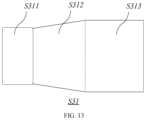
- FIG. 13 is a top view of the connecting subarea according to the second example of the present disclosure in FIG. 10 .
- the connecting subarea S 31 includes a connecting divisional area S 311 , a fifth bending area S 312 , and a sixth bending area S 313 .
- the connecting divisional area S 311 , the fifth bending area S 312 , and the sixth bending area S 313 are sequentially connected, and the sixth bending area S 313 is connected to the side wall area S 2 .
- the sixth bending area S 313 is bent toward the first surface facing to the side wall area S 2 to form a sixth bending plate 313
- the fifth bending area S 312 is bent toward the first surface facing to the sixth bending area S 313 to form a fifth bending plate 312 .
- the connecting divisional area S 311 are bent toward the second surface facing to the fifth bending area S 312 to form the connecting plate 311 .
- the packing box includes: a box body, which further comprises of a bottom, a side wall and a containing space; the side wall connects to the bottom and the containing space is formed by the bottom and the side wall; a carrying structure, positioned in the containing space, is connected to the side wall in one-piece structure with a bendable connection; the carrying structure includes the connecting part and the buffer part; wherein the said buffer part is connected to both ends of the connecting part along the second direction, and the carrying structure connects to the side wall through the connecting part; the buffer part is a structural component that is connected to the connecting part with a bendable connection, and the buffer part abuts against the side wall with a amount of deformation, and the effective space inside the box changes with the deformation of the buffer part.
- the carrying structure also comprises carrying part, and the carrying part connects to the connecting part at a side close to the bottom with a bendable connection, and the carrying part abuts against the bottom.
- carrying part is a flexible bent structure
- the flexible bent structure includes a first bending plate and a second bending plate.
- One end of the first bending plate is connected to the connecting part with a bendable connection
- the other end of the first bending plate is connected to the second bending plate with a bendable connection.
- the length of the fold line between the first bending plate and the connecting part is less than that between the first bending plate and the second bending plate; the bending angle between the first bending plate and the second bending plate is greater than 90° and less than 180°.
- the buffer part is a buffer bending structure;
- the buffer bending structure includes a third bending plate and a fourth bending plate; one end of the third bending plate is connected to the connecting part with a bendable connection, and the other end of the third bending plate is connected to one end of the fourth bending plate, and the other end of the fourth bending plate abuts against the side wall.
- the length of the fold line between the third bending plate and the fourth bending plate is less than the length of the side line of the fourth bending plate away from the third bending plate; the bending angle between the third bending plate and the fourth bending plate is greater than 90° and less than 180°.
- the side wall further includes fixing part; the fixing part is respectively connected to the two ends of the side wall along the first direction with a bendable connection; the fixing part is permanently connected with the side wall.
- the side wall further includes extension part; the extension part is connected to the fixing part with a bendable connection, and at least a part of the bottom is attached to the extension part.
- the connecting part is a connectable bending structure, the connectable bending structure includes a connecting plate, a fifth bending plate and a sixth bending plate that are sequentially connected together with a bendable connection; the buffer part is connected to the connecting plate with a bendable connection; the sixth bending plate is connected to the side wall with a bendable connection; the length of the fold line between the fifth bending plate and the connecting plate is smaller than that between the fifth bending plate and the sixth bending plate.
- the box forms a cuboid container.
- the packing box and the cardboard structure are provided by the embodiments of this application.
- the carrying structure with buffer part in the packing box to carry objects, and by using the deformable buffer part to buffer the objects, the buffer capacity of the packing box can be improved thereby.
- the carrying structure and the side wall of the packing box are a bendable one-piece structure, so that the carrying structure can be directly obtained by bending, consequently the process of adding buffer materials can be omitted, and the packaging process of the packing box is simplified.
- the examples of the present disclosure provide a packing box and a cardboard structure to improve its buffer capacity by arranging a carrying structure 3 with a buffer part 32 to carry objects.
- the carrying structure 3 and the side wall 2 are a bendable one-piece structure, the carrying structure 3 can be obtained by bending, so additional buffer materials can be omitted, thereby the manufacturing process of the packing box and the packaging process of the objects are simplified.
- the rebound effect of the carrying part 33 can lift the object up, which enhances the user's experience and feeling.
Landscapes
- Engineering & Computer Science (AREA)
- Mechanical Engineering (AREA)
- Cartons (AREA)
- Buffer Packaging (AREA)
Abstract
Description
Claims (11)
Applications Claiming Priority (2)
| Application Number | Priority Date | Filing Date | Title |
|---|---|---|---|
| CN202121684833.6 | 2021-07-22 | ||
| CN202121684833.6U CN215852375U (en) | 2021-07-22 | 2021-07-22 | Packing box and paperboard structure |
Publications (2)
| Publication Number | Publication Date |
|---|---|
| US20230026698A1 US20230026698A1 (en) | 2023-01-26 |
| US12240665B2 true US12240665B2 (en) | 2025-03-04 |
Family
ID=80331280
Family Applications (1)
| Application Number | Title | Priority Date | Filing Date |
|---|---|---|---|
| US17/517,638 Active US12240665B2 (en) | 2021-07-22 | 2021-11-02 | Packing box and cardboard structure |
Country Status (2)
| Country | Link |
|---|---|
| US (1) | US12240665B2 (en) |
| CN (1) | CN215852375U (en) |
Families Citing this family (4)
| Publication number | Priority date | Publication date | Assignee | Title |
|---|---|---|---|---|
| USRE50020E1 (en) * | 2018-08-03 | 2024-06-25 | Baselinx Llc | Temporary bulkhead for shipping container |
| JP2022523902A (en) * | 2019-03-06 | 2022-04-27 | テスルロン インコーポレイテッド | Separation member for box and packaging system including it |
| CN116002229A (en) * | 2021-10-22 | 2023-04-25 | 深圳市裕同包装科技股份有限公司 | Packing box |
| US12428194B2 (en) * | 2022-08-16 | 2025-09-30 | Pacific Southwest Container, LLC | Container assembly |
Citations (10)
| Publication number | Priority date | Publication date | Assignee | Title |
|---|---|---|---|---|
| US2399537A (en) * | 1944-05-18 | 1946-04-30 | Nat Union Radio Corp | Carton |
| US5193741A (en) * | 1992-03-02 | 1993-03-16 | Mark Magruder | Unistructurally formed merchandise display container and coin box |
| US5857612A (en) * | 1996-02-21 | 1999-01-12 | Motion Design, Inc. | Double panel boxes |
| US5871147A (en) * | 1996-02-21 | 1999-02-16 | Motion Design, Inc. | Double panel boxes |
| US20030024851A1 (en) * | 2000-11-10 | 2003-02-06 | Jean-Michel Auclair | Carton for fragile article |
| US20180022500A1 (en) * | 2016-06-13 | 2018-01-25 | The Procter & Gamble Company | Display box with retention means |
| US20200114612A1 (en) * | 2017-05-23 | 2020-04-16 | Philip Morris Products S.A. | Container with adhesive interaction portion, method and blank for forming the same |
| US20200385164A1 (en) * | 2019-06-06 | 2020-12-10 | Multi Packaging Solutions Uk Limited | Container |
| KR20220009752A (en) * | 2020-07-16 | 2022-01-25 | 테슬론 주식회사 | Spacer for box and packaging system for the same |
| US20220119150A1 (en) * | 2019-03-06 | 2022-04-21 | Tesllon Inc. | Spacing member for box, and packaging system including same |
-
2021
- 2021-07-22 CN CN202121684833.6U patent/CN215852375U/en active Active
- 2021-11-02 US US17/517,638 patent/US12240665B2/en active Active
Patent Citations (10)
| Publication number | Priority date | Publication date | Assignee | Title |
|---|---|---|---|---|
| US2399537A (en) * | 1944-05-18 | 1946-04-30 | Nat Union Radio Corp | Carton |
| US5193741A (en) * | 1992-03-02 | 1993-03-16 | Mark Magruder | Unistructurally formed merchandise display container and coin box |
| US5857612A (en) * | 1996-02-21 | 1999-01-12 | Motion Design, Inc. | Double panel boxes |
| US5871147A (en) * | 1996-02-21 | 1999-02-16 | Motion Design, Inc. | Double panel boxes |
| US20030024851A1 (en) * | 2000-11-10 | 2003-02-06 | Jean-Michel Auclair | Carton for fragile article |
| US20180022500A1 (en) * | 2016-06-13 | 2018-01-25 | The Procter & Gamble Company | Display box with retention means |
| US20200114612A1 (en) * | 2017-05-23 | 2020-04-16 | Philip Morris Products S.A. | Container with adhesive interaction portion, method and blank for forming the same |
| US20220119150A1 (en) * | 2019-03-06 | 2022-04-21 | Tesllon Inc. | Spacing member for box, and packaging system including same |
| US20200385164A1 (en) * | 2019-06-06 | 2020-12-10 | Multi Packaging Solutions Uk Limited | Container |
| KR20220009752A (en) * | 2020-07-16 | 2022-01-25 | 테슬론 주식회사 | Spacer for box and packaging system for the same |
Also Published As
| Publication number | Publication date |
|---|---|
| CN215852375U (en) | 2022-02-18 |
| US20230026698A1 (en) | 2023-01-26 |
Similar Documents
| Publication | Publication Date | Title |
|---|---|---|
| US12240665B2 (en) | Packing box and cardboard structure | |
| JP4284724B2 (en) | Packaging container | |
| US7931151B2 (en) | Suspension packaging system | |
| US20120234723A1 (en) | System and method of packaging | |
| US20100140333A1 (en) | Suspension packaging system | |
| JP2013103748A (en) | Corrugated cardboard cushioning material and corrugated cardboard box accommodated with the corrugated cardboard cushioning material | |
| US20130220866A1 (en) | Cushioning material | |
| CN101224811B (en) | Packing carton, buffer and panel | |
| KR102668712B1 (en) | Cushioning structure for packaging | |
| EP2590873B1 (en) | Dual-purpose packaging insert and packaging box for sensitive flat objects | |
| CN105730876A (en) | Packaging box for television set | |
| WO2023216944A1 (en) | Bottle packaging structure and box | |
| JP2019018895A (en) | Buffer material and packing method using the buffer material | |
| CN101920815A (en) | Buffer device of packing box | |
| JPH11236036A (en) | Package with buffer function | |
| TW201119917A (en) | Packing box structure | |
| TWM314190U (en) | Packing box | |
| CN101224806A (en) | Packing carton, buffer and panel | |
| CN211919290U (en) | Suspended packaging box | |
| KR200499633Y1 (en) | Packing Box | |
| CN103434755A (en) | Cushion packing unit and cushion packing box | |
| TWI308126B (en) | Package box, cushion and plate material | |
| US20230356909A1 (en) | Retention packaging system | |
| CN212126026U (en) | Packaging structure | |
| CN209956583U (en) | Buffering packing box |
Legal Events
| Date | Code | Title | Description |
|---|---|---|---|
| FEPP | Fee payment procedure |
Free format text: ENTITY STATUS SET TO UNDISCOUNTED (ORIGINAL EVENT CODE: BIG.); ENTITY STATUS OF PATENT OWNER: LARGE ENTITY |
|
| AS | Assignment |
Owner name: SHENZHEN YUTO PACKAGING TECHNOLOGY CO., LTD., CHINA Free format text: ASSIGNMENT OF ASSIGNORS INTEREST;ASSIGNOR:ZHENG, HAIXIA;REEL/FRAME:058070/0440 Effective date: 20211020 |
|
| STPP | Information on status: patent application and granting procedure in general |
Free format text: NON FINAL ACTION MAILED |
|
| STPP | Information on status: patent application and granting procedure in general |
Free format text: RESPONSE TO NON-FINAL OFFICE ACTION ENTERED AND FORWARDED TO EXAMINER |
|
| STPP | Information on status: patent application and granting procedure in general |
Free format text: FINAL REJECTION MAILED |
|
| STPP | Information on status: patent application and granting procedure in general |
Free format text: RESPONSE AFTER FINAL ACTION FORWARDED TO EXAMINER |
|
| STPP | Information on status: patent application and granting procedure in general |
Free format text: ADVISORY ACTION MAILED |
|
| STPP | Information on status: patent application and granting procedure in general |
Free format text: DOCKETED NEW CASE - READY FOR EXAMINATION |
|
| STPP | Information on status: patent application and granting procedure in general |
Free format text: NON FINAL ACTION MAILED |
|
| STPP | Information on status: patent application and granting procedure in general |
Free format text: RESPONSE TO NON-FINAL OFFICE ACTION ENTERED AND FORWARDED TO EXAMINER |
|
| STPP | Information on status: patent application and granting procedure in general |
Free format text: NOTICE OF ALLOWANCE MAILED -- APPLICATION RECEIVED IN OFFICE OF PUBLICATIONS |
|
| STPP | Information on status: patent application and granting procedure in general |
Free format text: PUBLICATIONS -- ISSUE FEE PAYMENT RECEIVED |
|
| STPP | Information on status: patent application and granting procedure in general |
Free format text: PUBLICATIONS -- ISSUE FEE PAYMENT VERIFIED |
|
| STCF | Information on status: patent grant |
Free format text: PATENTED CASE |