US12240442B2 - Vehicle information delivery device, vehicle information delivery method, and storage medium - Google Patents
Vehicle information delivery device, vehicle information delivery method, and storage medium Download PDFInfo
- Publication number
- US12240442B2 US12240442B2 US18/061,478 US202218061478A US12240442B2 US 12240442 B2 US12240442 B2 US 12240442B2 US 202218061478 A US202218061478 A US 202218061478A US 12240442 B2 US12240442 B2 US 12240442B2
- Authority
- US
- United States
- Prior art keywords
- vehicle
- information
- information delivery
- delivery device
- target area
- Prior art date
- Legal status (The legal status is an assumption and is not a legal conclusion. Google has not performed a legal analysis and makes no representation as to the accuracy of the status listed.)
- Active, expires
Links
Images


Classifications
-
- G—PHYSICS
- G06—COMPUTING OR CALCULATING; COUNTING
- G06V—IMAGE OR VIDEO RECOGNITION OR UNDERSTANDING
- G06V20/00—Scenes; Scene-specific elements
- G06V20/50—Context or environment of the image
- G06V20/52—Surveillance or monitoring of activities, e.g. for recognising suspicious objects
-
- B—PERFORMING OPERATIONS; TRANSPORTING
- B60—VEHICLES IN GENERAL
- B60W—CONJOINT CONTROL OF VEHICLE SUB-UNITS OF DIFFERENT TYPE OR DIFFERENT FUNCTION; CONTROL SYSTEMS SPECIALLY ADAPTED FOR HYBRID VEHICLES; ROAD VEHICLE DRIVE CONTROL SYSTEMS FOR PURPOSES NOT RELATED TO THE CONTROL OF A PARTICULAR SUB-UNIT
- B60W30/00—Purposes of road vehicle drive control systems not related to the control of a particular sub-unit, e.g. of systems using conjoint control of vehicle sub-units
- B60W30/06—Automatic manoeuvring for parking
-
- G—PHYSICS
- G06—COMPUTING OR CALCULATING; COUNTING
- G06V—IMAGE OR VIDEO RECOGNITION OR UNDERSTANDING
- G06V20/00—Scenes; Scene-specific elements
- G06V20/40—Scenes; Scene-specific elements in video content
- G06V20/46—Extracting features or characteristics from the video content, e.g. video fingerprints, representative shots or key frames
-
- G—PHYSICS
- G06—COMPUTING OR CALCULATING; COUNTING
- G06V—IMAGE OR VIDEO RECOGNITION OR UNDERSTANDING
- G06V20/00—Scenes; Scene-specific elements
- G06V20/50—Context or environment of the image
- G06V20/56—Context or environment of the image exterior to a vehicle by using sensors mounted on the vehicle
-
- G—PHYSICS
- G06—COMPUTING OR CALCULATING; COUNTING
- G06V—IMAGE OR VIDEO RECOGNITION OR UNDERSTANDING
- G06V20/00—Scenes; Scene-specific elements
- G06V20/60—Type of objects
-
- B—PERFORMING OPERATIONS; TRANSPORTING
- B60—VEHICLES IN GENERAL
- B60W—CONJOINT CONTROL OF VEHICLE SUB-UNITS OF DIFFERENT TYPE OR DIFFERENT FUNCTION; CONTROL SYSTEMS SPECIALLY ADAPTED FOR HYBRID VEHICLES; ROAD VEHICLE DRIVE CONTROL SYSTEMS FOR PURPOSES NOT RELATED TO THE CONTROL OF A PARTICULAR SUB-UNIT
- B60W2420/00—Indexing codes relating to the type of sensors based on the principle of their operation
- B60W2420/40—Photo, light or radio wave sensitive means, e.g. infrared sensors
- B60W2420/403—Image sensing, e.g. optical camera
-
- B—PERFORMING OPERATIONS; TRANSPORTING
- B60—VEHICLES IN GENERAL
- B60W—CONJOINT CONTROL OF VEHICLE SUB-UNITS OF DIFFERENT TYPE OR DIFFERENT FUNCTION; CONTROL SYSTEMS SPECIALLY ADAPTED FOR HYBRID VEHICLES; ROAD VEHICLE DRIVE CONTROL SYSTEMS FOR PURPOSES NOT RELATED TO THE CONTROL OF A PARTICULAR SUB-UNIT
- B60W2556/00—Input parameters relating to data
- B60W2556/45—External transmission of data to or from the vehicle
Definitions
- the present disclosure relates to a vehicle information delivery device, a vehicle information delivery method, and a storage medium.
- JP 2018-204373 A describes a parking facility for unattended parking of autonomous vehicles and non-autonomous vehicles.
- an autonomous vehicle moves autonomously to a parking space while a non-autonomous vehicle is conveyed to a parking space by an autonomous conveyor.
- information on a vehicle moving unmanned can be provided to the user of the vehicle.
- FIG. 1 is a schematic configuration diagram of an automated parking system according to a first embodiment of the present disclosure
- FIG. 2 is a diagram showing an example of a status in which unattended parking is performed in a predetermined target area
- FIG. 3 is a schematic configuration diagram of a vehicle information delivery system according to the first embodiment of the present disclosure
- FIG. 4 is a diagram schematically showing the configuration of an information delivery server
- FIG. 5 is a functional block diagram of a processor of the information delivery server in the first embodiment
- FIG. 6 is a flowchart showing the control routine of camera image processing in the first embodiment
- FIG. 7 is a flowchart showing the control routine of information sending processing in the first embodiment
- FIG. 8 is a schematic configuration diagram of an automated parking system according to a second embodiment of the present disclosure.
- FIG. 9 is a diagram showing an example of a status in which unattended parking is performed in a predetermined target area
- FIG. 10 is a diagram schematically showing a vehicle conveyor used in a third embodiment
- FIG. 11 is a functional block diagram of a processor of an information delivery server in the third embodiment.
- FIG. 12 is a flowchart showing the control routine of abnormality diagnosis processing in the third embodiment
- FIG. 13 is a functional block diagram of a processor of an information delivery server in a fourth embodiment
- FIG. 14 is a flowchart showing the control routine of position information acquisition processing in the fourth embodiment.
- FIG. 15 is a flowchart showing the control routine of information sending processing in the fourth embodiment.
- FIG. 16 is a functional block diagram of a processor of an information delivery server in a fifth embodiment.
- FIG. 17 is a flowchart showing the control routine of information sending processing in the fifth embodiment.
- FIG. 1 is a schematic configuration diagram of an automated parking system 100 according to the first embodiment of the present disclosure.
- the automated parking system 100 includes a parking control server 10 and at least one vehicle 20 to implement unattended parking.
- the parking control server 10 can communicate with the vehicle 20 via a wireless base station 30 , such as a macro cell or a small cell, and a communication network 40 such as the Internet network or a carrier network.
- the vehicle 20 an autonomous vehicle in which acceleration, steering, and deceleration (braking) of the vehicle 20 are all performed automatically, has a known configuration (in-vehicle camera 21 , GNSS receiver, drive motor, brake actuator, steering motor, etc.) for implementing autonomous driving.
- the vehicle 20 is capable of unmanned driving and performs unattended parking in a predetermined target area according to an instruction from the parking control server 10 .
- FIG. 2 is a diagram showing an example of a status in which unattended parking is performed in a predetermined target area 500 .
- the target area 500 is the parking lot of a facility such as an airport, a station, an amusement park, a hospital, a stadium, or a shopping center.
- the target area 500 has a plurality of boarding and alighting spaces 510 where the users (occupants) of the vehicles 20 get in or out of the vehicles and a plurality of parking spaces 520 where the vehicles 20 are parked.
- the vehicle 20 moves unmanned for parking in, or exiting from, the parking lot.
- boarding and alighting spaces 510 are provided near the entrance of the target area.
- one vehicle 20 is stopped.
- the user of the vehicle 20 gets out of the vehicle 20 in one of the boarding and alighting spaces 510 .
- the vehicle 20 is to exit from the parking lot, the user of the vehicle 20 gets in the vehicle 20 in one of the boarding and alighting spaces 510 .
- the boarding and alighting spaces 510 may be provided in an open space or in a garage-like space that can be opened and closed. Note that, in the target area 500 , the space where the user of the vehicle 20 gets out of the vehicle 20 for parking in the parking lot and the space where the user of the vehicle 20 gets in the vehicle 20 for exiting from the parking lot may be provided separately.
- thirty parking spaces 520 are provided in the area in front of the boarding and alighting spaces 510 .
- one vehicle 20 is parked.
- the vehicle 20 moves unmanned from the boarding and alighting space 510 to the parking space 520 autonomously.
- the vehicle 20 moves unmanned from parking space 520 to the boarding and alighting space 510 autonomously.
- the parking control server 10 is arranged, for example, in a parking management center 530 provided near the boarding and alighting space 510 .
- the parking control server 10 which includes a communication interface, a storage device, a memory, a processor, etc., manages unattended parking in the target area 500 .
- the parking control server 10 sends an instruction to the vehicle 20 to indicate the parking space 520 where the vehicle 20 is to park and, when the vehicle 20 is to exit from the parking lot, sends an instruction to the vehicle 20 to indicate the boarding and alighting space 510 where the vehicle 20 is to stop.
- the vehicle 20 When unattended parking as described above is performed, the vehicle 20 is handed over in the boarding and alighting space 510 , with no need for the user of the vehicle 20 to enter the parking area where the vehicle 20 moves unmanned. This eliminates the need to secure a space in the parking area where the user of the vehicle 20 gets in and out of the vehicle, providing more parking spaces 520 in the predetermined range. This also frees the user of the vehicle 20 from a bothersome task of parking, such as searching for the parking space 520 and manipulating the vehicle for parking.
- this embodiment monitors the status of the vehicle 20 moving unmanned in the target area 500 and, when necessary, delivers the information indicating the status of the vehicle 20 to the user of the vehicle 20 , as will be described in detail below.
- FIG. 3 is a schematic configuration diagram of a vehicle information delivery system 200 according to the first embodiment of the present disclosure.
- the vehicle information delivery system 200 includes an information delivery server 1 and at least one camera 2 .
- the information distribution server 1 can communicate with the camera 2 and the vehicle 20 via the wireless base station 30 , such as a macro cell or a small cell, and the communication network 40 such as the Internet network or a carrier network.
- the wireless base station 30 such as a macro cell or a small cell
- the communication network 40 such as the Internet network or a carrier network.
- the camera 2 takes the picture of the target area 500 to generate an image of the target area 500 .
- the camera 2 is a fixed camera arranged in the target area 500 .
- a plurality of (four) fixed cameras 540 arranged at the four corners of the target area 500 , collaborate to take the picture of the entire target area 500 .
- the number and position of the fixed cameras 540 are set so that there are no blind spots in the target area 500 .
- the fixed cameras are also called infrastructure cameras.
- the information delivery server 1 uses the camera 2 to deliver the information on the vehicle 20 in the target area 500 to the user of the vehicle 20 .
- the information delivery server 1 is an example of a vehicle information delivery device. As shown in FIG. 2 , the information delivery server 1 is arranged, for example, in the parking management center 530 .
- the information delivery server 1 and the parking control server 10 may be the same server.
- FIG. 4 is a diagram schematically showing the configuration of the information delivery server 1 .
- the information delivery server 1 includes a communication interface 11 , a storage device 12 , a memory 13 , and a processor 14 .
- the communication interface 11 , the storage device 12 , and the memory 13 are connected to the processor 14 via a signal line.
- the information delivery server 1 may further include an input device, such as a keyboard and a mouse, and an output device such as a display.
- the information delivery server 1 may be configured by a plurality of computers.
- the communication interface 11 has an interface circuit for connecting the information delivery server 1 to the communication network 40 .
- the information delivery server 1 communicates with the camera 2 and the vehicle 20 via the communication network 40 .
- the communication interface 11 is an example of the communication unit of the information delivery server 1 .
- the storage device 12 includes, for example, a hard disk drive (HDD), a solid state drive (SDD), or an optical recording medium and an access device thereof.
- the storage device 12 which stores various types of data, stores computer programs such as those used by the processor 14 to perform various types of processing.
- the storage device 12 is an example of the storage unit of the information delivery server 1 .
- the memory 13 includes a non-volatile semiconductor memory (for example, RAM).
- the memory 13 temporarily stores various types of data such as data that is used when the processor 14 performs various types of processing.
- the memory 13 is another example of the storage unit of the information delivery server 1 .
- the processor 14 includes one or more CPUs and their peripheral circuits to perform various types of processing.
- the processor 14 may further include other arithmetic circuits such as a logical operation unit, a numerical operation unit, or a graphic processing unit.
- FIG. 5 is a functional block diagram of the processor 14 of the information delivery server 1 in the first embodiment.
- the processor 14 includes an image processing unit 15 and an information sending unit 16 .
- the image processing unit 15 and the information sending unit 16 are functional modules implemented when the processor 14 of the information delivery server 1 executes computer programs stored in the memory 13 of the information delivery server 1 .
- Each of these functional modules may be implemented by a dedicated arithmetic circuit provided in the processor 14 .
- the image processing unit 15 processes the camera images taken in the target area 500 . More specifically, based on the camera images taken in the target area 500 , the image processing unit 15 generates vehicle related images showing the status of the vehicle 20 moving unmanned in the target area 500 .
- the information sending unit 16 sends the delivery information, which includes the vehicle related images, to the display terminal visually recognized by the user of the vehicle 20 .
- the information delivery server 1 can communicate with a mobile terminal 3 of the user of the vehicle 20 via the wireless base station 30 and the communication network 40 as shown in FIG. 3 , the information sending unit 16 sends the delivery information to the mobile terminal 3 .
- the mobile terminal 3 is a terminal such as a smartphone, a tablet terminal, and a watch-type terminal (smart watch).
- Sending the delivery information, which includes the vehicle related images showing the status of the vehicle 20 moving unmanned, to the display terminal as mentioned above makes it possible to provide the information on the vehicle 20 to the user of the vehicle 20 , thus reducing user anxiety about unattended parking.
- the information sending unit 16 sends the delivery information to the mobile terminal 3 of the user of the vehicle 20 when the movement of the vehicle 20 is completed. This eliminates the need for the user of the vehicle 20 to have to check the status of the vehicle 20 frequently, improving the convenience of the user.
- FIG. 6 is a flowchart showing the control routine of the camera image processing in the first embodiment. This control routine is executed by the processor 14 of the information delivery server 1 according to computer programs stored in the memory 13 of the information delivery server 1 .
- FIG. 8 is a schematic configuration diagram of an automated parking system 100 ′ according to the second embodiment of the present disclosure.
- the automated parking system 100 ′ includes a parking control server 10 ′ and at least one vehicle conveyor 50 to implement unattended parking.
- the parking control server 10 ′ can communicate with the vehicle conveyor 50 via the wireless base station 30 such as a macro cell or a small cell and a communication network 40 such as the Internet network or a carrier network.
- the vehicle conveyor 50 a self-propelled vehicle conveyor, has a known configuration for autonomously conveying a vehicle 20 ′ (see, for example, U.S. Pat. No. 10,590,669, JP 2018-204373 A). For example, from the front or rear of the vehicle 20 ′, the vehicle conveyor 50 inserts the carriage into the space between the bottom of the vehicle 20 ′ and the road surface to lift the four tires of the vehicle 20 ′ for supporting and conveying the vehicle 20 ′.
- the vehicle conveyor 50 conveys the vehicle 20 ′ so that the vehicle 20 ′ can park in, or exit from, the parking lot. More specifically, the vehicle conveyor 50 conveys the vehicle 20 ′ from the boarding and alighting space 510 ′ to the parking space 520 ′ when the vehicle 20 ′ is to park in the parking lot, and from the parking space 520 ′ to the boarding and alighting space 510 ′ when the vehicle 20 ′ is to exit from the parking lot. Therefore, even when the vehicle 20 ′ is a non-autonomous vehicle that does not have the autonomous driving function (that is, a manual driving vehicle), the vehicle 20 ′ can move unmanned to park in, or exit from, the parking lot for implementing unattended parking.
- the vehicle 20 ′ can move unmanned to park in, or exit from, the parking lot for implementing unattended parking.
- the alighting space where the user of the vehicle 20 ′ gets out from the vehicle 20 ′ for parking in the parking lot and the boarding space where the user of the vehicle 20 ′ gets in the vehicle 20 ′ for exiting from the parking lot may be provided separately.
- the parking control server 10 ′ is arranged, for example, in a parking management center 530 ′ provided near the boarding and alighting space 510 ′.
- the parking control server 10 ′ which includes a communication interface, a storage device, a memory, a processor, etc., manages unattended parking in the target area 500 ′. For example, when the vehicle 20 ′ is to park in, or exit from, the parking lot, the parking control server 10 ′ selects one of the vehicle conveyors 50 that will convey the vehicle 20 ′ and sends a vehicle conveyance instruction to the vehicle conveyor 50 .
- the vehicle conveyance instruction includes, for example, the current position of the vehicle 20 ′ to be conveyed (for example, the identification number of the boarding and alighting space 510 ′ or parking space 520 ′), the information on the conveyance destination (for example, the identification number of the parking space 520 ′ or the boarding and alighting space 510 ′).
- the information delivery server 1 which functions as the vehicle information delivery device, delivers the information on the vehicle 20 ′ in the target area 500 ′ to the user of the vehicle 20 ′.
- the image processing unit 15 of the information delivery server 1 generates vehicle related images, which show the status of the vehicle 20 ′ moving unmanned in the target area 500 ′, based on the camera images taken in the target area 500 ′.
- the information sending unit 16 of the information delivery server 1 sends the delivery information, which includes the vehicle related images, to the display terminal (e.g., the mobile terminal 3 of the user) visually recognized by the user of the vehicle 20 ′.
- the control routine of the camera image processing shown in FIG. 6 and the control routine of the information sending processing shown in FIG. 7 are executed as in the first embodiment.
- step S 102 in FIG. 6 the images taken by the camera 51 provided on the vehicle conveyor 50 are acquired as the camera images taken in the target area 500 .
- step S 103 these images are stored in the storage device 12 or the memory 13 of the information delivery server 1 as the vehicle related images.
- step S 203 in FIG. 7 the images taken by the camera 51 are sent to the mobile terminal 3 of the user of the vehicle 20 ′ as the delivery information. Therefore, the second embodiment can provide the user of vehicle 20 ′ with a realistic image of vehicle 20 ′ taken in the vicinity of vehicle 20 ′ by the camera 51 of the vehicle transport device 50 .
- a vehicle information delivery device is basically the same as the vehicle information delivery device according to the second embodiment except for the points described below. Therefore, the third embodiment of the present disclosure will be described below with focus on the parts different from the first embodiment.
- FIG. 10 is a diagram schematically showing a vehicle conveyor 50 ′ used in the third embodiment.
- the vehicle conveyor 50 ′ includes two cameras (a first camera 51 ′ and a second camera 52 ) as shown in FIG. 10 .
- the first camera 51 ′ similar to the camera 51 shown in FIG. 8 , takes the picture of the vehicle 20 ′ along with the surroundings of the vehicle 20 ′ when the vehicle conveyor 50 ′ conveys the vehicle 20 ′.
- the second camera 52 takes the picture of the bottom of the vehicle 20 ′ when the carriage of the vehicle conveyor 50 ′ is inserted into the space between the bottom of the vehicle 20 ′ and the road surface.
- FIG. 11 is a functional block diagram of the processor 14 of the information delivery server 1 in the third embodiment.
- the processor 14 includes an abnormality diagnosis unit 17 in addition to the image processing unit 15 and the information sending unit 16 .
- the image processing unit 15 , the information sending unit 16 , and the abnormality diagnosis unit 17 are functional modules implemented when the processor 14 of the information delivery server 1 executes computer programs stored in the memory 13 of the information delivery server 1 .
- Each of these functional modules may be implemented by a dedicated arithmetic circuit provided in the processor 14 .
- the abnormality diagnosis unit 17 performs an abnormality diagnosis of the vehicle 20 ′, supported by the vehicle conveyor 50 ′, based on the image the bottom of the vehicle 20 ′ taken by the second camera 52 . This makes it possible to easily perform an abnormality diagnosis of the bottom of the vehicle 20 ′, where visual check is difficult, during unattended parking of the vehicle 20 ′, thus providing an additional service to the user of the vehicle 20 ′.
- the abnormality diagnosis unit 17 sends the result of abnormality diagnosis to the mobile terminal 3 of the user of the vehicle 20 ′. This allows the user of the vehicle 20 ′, when an abnormality is detected in the bottom of the vehicle 20 ′, to recognize the abnormality and to urge the user of the vehicle 20 ′ to inspect the vehicle.
- Examples of abnormalities in the bottom (on the underside) of the vehicle 20 ′ include rust, corrosion, or damage in parts, and oil leakage.
- FIG. 12 is a flowchart showing the control routine of the abnormality diagnosis processing in the third embodiment. This control routine is executed by the processor 14 of the information delivery server 1 according to computer programs stored in the memory 13 of the information delivery server 1 .
- the abnormality diagnosis unit 17 determines whether a camera image taken by the second camera 52 is received from the vehicle conveyor 50 ′. For example, when the conveyance of the vehicle 20 ′ for parking in the parking lot is started in the boarding and alighting space 510 ′, the vehicle conveyor 50 ′ uses the second camera 52 to take the picture of the bottom of the vehicle 20 ′ and sends the camera image, taken by second camera 52 , to the information delivery server 1 .
- the vehicle conveyor 50 ′ may use the second camera 52 to take the picture of the bottom of the vehicle 20 ′ and sends the camera image, taken by the second camera 52 , to the information delivery server 1 .
- step S 301 When it is determined in step S 301 that a camera image is not received, this control routine ends. On the other hand, when it is determined in step S 301 that a camera image is received, the processing of this control routine proceeds to step S 302 .
- the abnormality diagnosis unit 17 performs an abnormality diagnosis of the vehicle 20 ′ based on the camera image taken by the second camera 52 .
- the abnormality diagnosis unit 17 performs an abnormality diagnosis of the vehicle 20 ′ using a discriminator that is pre-trained in advance so as to output an abnormality in the vehicle 20 ′ from the camera image if any.
- discriminators include machine learning models such as neural networks, support vector machines, and random forests.
- step S 303 the abnormality diagnosis unit 17 determines whether an abnormality is detected in the vehicle 20 ′. When it is determined that no abnormality is detected in the vehicle 20 ′, this control routine ends. On the other hand, when it is determined that an abnormality is detected in the vehicle 20 ′, the processing of this control routine proceeds to step S 304 .
- step S 304 the abnormality diagnosis unit 17 sends the result of abnormality diagnosis to the mobile terminal 3 of the user of the vehicle 20 ′ to notify the user of the abnormality in the vehicle 20 ′ via the mobile terminal 3 .
- this control routine ends.
- a vehicle information delivery device is basically the same as the vehicle information delivery device according to the first embodiment except for the points described below. Therefore, the fourth embodiment of the present disclosure will be described below with focus on the parts different from the first embodiment.
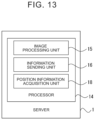
- FIG. 13 is a functional block diagram of the processor 14 of the information delivery server 1 in the fourth embodiment.
- the processor 14 includes a position information acquisition unit 18 in addition to the image processing unit 15 and the information sending unit 16 .
- the image processing unit 15 , the information sending unit 16 , and the position information acquisition unit 18 are functional modules implemented when the processor 14 of the information delivery server 1 executes computer programs stored in the memory 13 of the information delivery server 1 .
- Each of these functional modules may be implemented by a dedicated arithmetic circuit provided in the processor 14 .
- the position information acquisition unit 18 acquires the position information on the vehicle 20 moving unmanned in the target area 500 , and the information sending unit 16 sends the delivery information that includes the position information on the vehicle 20 in addition to the vehicle related images to the mobile terminal 3 of the user of the vehicle 20 . This allows the user to know the position of the vehicle 20 in the target area 500 , further enhancing a user's sense of security.
- the position information acquisition unit 18 calculates the estimated required time to complete the movement of the vehicle 20 based on the position information on the vehicle 20 , and the information sending unit 16 sends the delivery information that includes the estimated required time in addition to the vehicle related images to the mobile terminal 3 of the user of the vehicle 20 . This allows the user of the vehicle 20 to more accurately understand the movement status of the vehicle 20 , further improving the convenience of the user.
- the position information acquisition unit 18 determines whether the movement of the vehicle 20 for exiting from the parking lot will be completed by the scheduled time, based on the estimated required time, and the information sending unit 16 sends the delivery information that includes the estimated required time in addition to the vehicle related images to the mobile terminal 3 of the user of the vehicle 20 when it is determined that the movement of the vehicle 20 for exiting from the parking lot will not be completed by the scheduled time.
- This allows the user of the vehicle 20 to be notified in advance that the movement of the vehicle 20 for exiting from the parking lot will not be completed by the scheduled time, thus reducing user's anxiety due to the non-arrival of the vehicle 20 .
- FIG. 14 is a flowchart showing the control routine of the position information acquisition processing in the fourth embodiment. This control routine is executed by the processor 14 of the information delivery server 1 according to computer programs stored in the memory 13 of the information delivery server 1 .
- step S 401 the position information acquisition unit 18 determines whether the vehicle 20 is moving unmanned in the target area 500 , that is, whether the vehicle 20 is parking in, or existing from, the target area 500 . This determination is executed in the same manner as in step S 101 in FIG. 6 . When it is determined that the vehicle 20 is moving unmanned, the processing of this control routine proceeds to step S 402 .
- step S 402 the position information acquisition unit 18 acquires the position information on the vehicle 20 (for example, the output of the GNSS receiver provided in the vehicle 20 ).
- step S 403 the position information acquisition unit 18 calculates the estimated required time to complete the movement of the vehicle 20 based on the position information on the vehicle 20 .
- the position information acquisition unit 18 calculates the estimated required time by dividing the movement distance, from the current position of the vehicle 20 to the movement completion point of the vehicle 20 (parking space 520 or the boarding and alighting space 510 ), by the predetermined movement speed.
- step S 404 the position information acquisition unit 18 determines whether the vehicle 20 is moving for exiting from the parking lot.
- the processing of this control routine proceeds to step S 405 .
- step S 405 based on the estimated required time to complete the movement of the vehicle 20 , the position information acquisition unit 18 determines whether the movement of the vehicle 20 for exiting from the parking lot will be completed by the scheduled time.
- the scheduled time is set by the user of the vehicle 20 or by the parking control server 10 , for example, when the vehicle 20 is parked in the parking lot.
- the processing of this control routine proceeds to step S 406 .
- step S 406 the position information acquisition unit 18 sets the flag F to 1. After step S 406 , this control routine ends.
- step S 401 or S 404 determines whether the determination in step S 401 or S 404 is negative or the determination in S 405 is affirmative.
- step S 407 the position information acquisition unit 18 resets the flag F to 0. After step S 407 , this control routine ends.
- FIG. 15 is a flowchart showing the control routine of the information sending processing in the fourth embodiment. This control routine is executed by the processor 14 of the information delivery server 1 according to computer program stored in the memory 13 of the information delivery server 1 .
- step S 501 the information sending unit 16 determines whether the flag F is set to 1. When it is determined that the flag F is set to 1, the processing of this control routine proceeds to step S 504 .
- step S 504 the information sending unit 16 sends the delivery information to the mobile terminal 3 of the user of the vehicle 20 .
- the information sending unit 16 sends the following three types of information to the mobile terminal 3 of the user of the vehicle 20 as the delivery information: the vehicle related images showing the current status of the vehicle 20 , the position information on the vehicle 20 , and the estimated required time to complete the movement of the vehicle 20 .
- the position information on the vehicle 20 is sent, the map of the target area 500 , together with the current position of the vehicle 20 on the map, is shown.
- the position information on the vehicle 20 may be omitted from the delivery information.
- step S 501 when it is determined in step S 501 that the flag F is set to 0, the processing of this control routine proceeds to step S 502 .
- steps S 502 to S 504 are executed in the same manner as steps S 201 to S 203 in FIG. 7 .
- step S 502 When the determination in step S 502 is affirmative, at least one of the position information on the vehicle 20 and the estimated required time to complete the movement of the vehicle 20 in addition to the vehicle related images may be sent as the delivery information.
- step S 503 When the determination in step S 503 is affirmative, the position information on the vehicle 20 in addition to the vehicle related images may be sent as the delivery information.
- a vehicle information delivery device is basically the same as the vehicle information delivery device according to the first embodiment except for the points described below. Therefore, the fifth embodiment of the present disclosure will be described below with focus on the parts different from the first embodiment.
- FIG. 16 is a functional block diagram of the processor 14 of the information delivery server 1 in the fifth embodiment.
- the processor 14 includes an abnormality detection unit 19 in addition to the image processing unit 15 and the information sending unit 16 .
- the image processing unit 15 , the information sending unit 16 , and the abnormality detection unit 19 are functional modules implemented when the processor 14 of the information delivery server 1 executes computer programs stored in the memory 13 of the information delivery server 1 .
- Each of these functional modules may be implemented by a dedicated arithmetic circuit provided in the processor 14 .
- the abnormality detection unit 19 detects an abnormality related to the movement of the vehicle 20 and, when an abnormality related to the movement of the vehicle 20 is detected, the information sending unit 16 sends the delivery information to the mobile terminal 3 of the user of the vehicle 20 . This makes it possible to quickly notify the user of the vehicle 20 that an abnormality has occurred in the movement of the vehicle 20 .
- the abnormality detection unit 19 detects an abnormality related to the movement of the vehicle 20 based on the camera images taken in the target area 500 .
- the abnormality detection unit 19 determines that an abnormality has occurred in the movement of vehicle 20 .
- the abnormality detection unit 19 determines that an abnormality has occurred in the movement of the vehicle 20 .
- the abnormality detection unit 19 may detect an abnormality related to movement of the vehicle 20 based on information sent from the vehicle 20 to the information delivery server 1 (for example, position information on the vehicle 20 ).
- FIG. 17 is a flowchart showing the control routine of the information sending processing in the fifth embodiment. This control routine is executed by the processor 14 of the information delivery server 1 according to computer programs stored in the memory 13 of the information delivery server 1 .
- step S 601 when it is determined in step S 601 that no abnormality related to the movement of the vehicle 20 is detected, the processing of this control routine proceeds to step S 602 .
- steps S 602 -S 604 are executed in the same manner as steps S 201 -S 203 in FIG. 7 .
- the information sending unit 16 may send the delivery information to an output device (display, digital signage, etc.) installed in a predetermined location (such as a predetermined facility near the boarding and alighting space 510 or boarding and alighting space 510 ′ or adjacent to the target area 500 ′).
- an output device display, digital signage, etc.
- a predetermined location such as a predetermined facility near the boarding and alighting space 510 or boarding and alighting space 510 ′ or adjacent to the target area 500 ′.
- unattended parking may be performed for both autonomous vehicles and non-autonomous vehicles.
- the camera images taken by the fixed cameras 540 ′ may be acquired as the camera images taken in the target area 500 ′.
- the camera 51 may be provided on the vehicle conveyor 50 to take only the surroundings of the vehicle 20 ′.
- a computer program that causes a computer to implement the functions of the units of the processor 14 of the information delivery server 1 may be provided in a form stored in a computer-readable recording medium (storage medium).
- a computer-readable recording medium is, for example, a magnetic recording medium, an optical recording medium, or a semiconductor memory.
- the embodiments described above may be performed in any combinations.
- the vehicle 20 ′ is conveyed by the vehicle conveyor 50 in the fourth embodiment.
- the position information acquisition unit 18 acquires, for example, the output of the GNSS receiver, which is provided on the vehicle conveyor 50 , from the vehicle conveyor 50 as the position information on the vehicle 20 .
- the abnormality detection unit 19 detects an abnormality in the vehicle conveyor 50 as an abnormality related to the movement of the vehicle 20 ′ in the fifth embodiment. For example, the abnormality detection unit 19 determines that an abnormality has occurred in the movement of the vehicle 20 ′ when it is detected that the vehicle conveyor 50 comes into contact with an obstacle (for example, another vehicle conveyor, a falling object) based on the camera images taken in the target area 500 or based on the information sent from the vehicle conveyor 50 to the information delivery server 1 .
- an obstacle for example, another vehicle conveyor, a falling object
- the vehicle 20 ′ is conveyed by the vehicle conveyor 50 ′ and the control routine of the abnormality diagnosis processing shown in FIG. 12 is executed in the fourth or fifth embodiment.
Landscapes
- Engineering & Computer Science (AREA)
- Physics & Mathematics (AREA)
- General Physics & Mathematics (AREA)
- Multimedia (AREA)
- Theoretical Computer Science (AREA)
- Automation & Control Theory (AREA)
- Transportation (AREA)
- Mechanical Engineering (AREA)
- Traffic Control Systems (AREA)
Abstract
Description
-
- (1) A first aspect of the present disclosure relates to a vehicle information delivery device including an image processing unit and an information sending unit. The image processing unit is configured to generate vehicle related images based on camera images taken in a predetermined target area where unattended parking is performed. The vehicle related images indicate the status of a vehicle moving unmanned in the target area. The information sending unit is configured to send delivery information including the vehicle related images to a display terminal visually recognized by the user of the vehicle.
- (2) In the vehicle information delivery device according to (1) described above, the display terminal may be the mobile terminal of the user.
- (3) In the vehicle information delivery device according to (1) or (2) described above, the vehicle related images may be moving images indicating the status of the vehicle and having a playback speed that has been changed.
- (4) In the vehicle information delivery device according to any one of (1) to (3) described above, the information sending unit may be configured to send the delivery information to the display terminal when the movement of the vehicle is completed.
- (5) In the vehicle information delivery device according to any one of (1) to (4) described above, the camera images may include the appearance images of the vehicle.
- (6) In the vehicle information delivery device according to any one of (1) to (5) described above, the vehicle may be conveyed in the target area by a vehicle conveyor and the camera images may be images taken by a camera mounted on the vehicle conveyor.
- (7) The vehicle information delivery device according to any one of (1) to (6) described above may further include an abnormality diagnosis unit configured to perform the abnormality diagnosis of the vehicle. In the vehicle information delivery device, the vehicle may be conveyed in the target area by a vehicle conveyor, and the abnormality diagnosis unit may be configured to perform the abnormality diagnosis of the vehicle based on the image of the bottom of the vehicle taken by a camera provided on the vehicle conveyor.
- (8) In the vehicle information delivery device according to (7) described above, the abnormality diagnosis unit may be configured to send the result of the abnormality diagnosis to the mobile terminal of the user of the vehicle when an abnormality is detected in the vehicle.
- (9) The vehicle information delivery device according to any one of (1) to (8) described above may further include a position information acquisition unit configured to acquire position information on the vehicle. In the vehicle information delivery device, the delivery information may include the position information on the vehicle.
- (10) The vehicle information delivery device according to any one of (1) to (9) described above may further include a position information acquisition unit configured to acquire the position information on the vehicle. In the vehicle information delivery device, the position information acquisition unit may be configured to calculate an estimated required time to complete the movement of the vehicle based on the position information, and the delivery information may include the estimated required time.
- (11) In the vehicle information delivery device according to (10) described above, the position information acquisition unit may be configured to determine, based on the estimated required time, whether the movement of the vehicle for exiting from the parking lot will be completed by the scheduled time, and the information sending unit may be configured to send the delivery information to the display terminal when it is determined that the movement of the vehicle for exiting from the parking lot will not be completed by the scheduled time.
- (12) The vehicle information delivery device according to any one of (1) to (11) described above may further include an abnormality detection unit configured to detect an abnormality related to the movement of the vehicle. In the vehicle information delivery device, the information sending unit may be configured to send the delivery information to the display terminal when an abnormality related to the movement of the vehicle is detected.
- (13) In the vehicle information delivery device according to (12) described above, the vehicle may be conveyed in the target area by the vehicle conveyor, and the abnormality detection unit may be configured to detect an abnormality in the vehicle conveyor as the abnormality related to the movement of the vehicle.
- (14) A second aspect of the present disclosure relates to a vehicle information delivery method performed by a computer and including generating and sending. The generating generates vehicle related images based on camera images taken in a predetermined target area where unattended parking is performed. The vehicle related images indicate the status of a vehicle moving unmanned in the target area. The sending sends delivery information including the vehicle related images to a display terminal visually recognized by the user of the vehicle.
- (15) A third aspect of the present disclosure relates to a storage medium storing a computer program for delivering vehicle information. The computer program causes a computer to perform processing to generate and to send. The processing to generate generates vehicle related images based on camera images taken in the target area where unattended parking is performed. The vehicle related images indicate the status of a vehicle moving unmanned in a predetermined target area. The processing to send sends delivery information including the vehicle related images to a display terminal visually recognized by a user of the vehicle.
Claims (17)
Applications Claiming Priority (2)
| Application Number | Priority Date | Filing Date | Title |
|---|---|---|---|
| JP2022003227A JP7666338B2 (en) | 2022-01-12 | 2022-01-12 | Vehicle information distribution device, vehicle information distribution method, and computer program for vehicle information distribution |
| JP2022-003227 | 2022-01-12 |
Publications (2)
| Publication Number | Publication Date |
|---|---|
| US20230219563A1 US20230219563A1 (en) | 2023-07-13 |
| US12240442B2 true US12240442B2 (en) | 2025-03-04 |
Family
ID=87070071
Family Applications (1)
| Application Number | Title | Priority Date | Filing Date |
|---|---|---|---|
| US18/061,478 Active 2043-08-11 US12240442B2 (en) | 2022-01-12 | 2022-12-05 | Vehicle information delivery device, vehicle information delivery method, and storage medium |
Country Status (2)
| Country | Link |
|---|---|
| US (1) | US12240442B2 (en) |
| JP (1) | JP7666338B2 (en) |
Families Citing this family (1)
| Publication number | Priority date | Publication date | Assignee | Title |
|---|---|---|---|---|
| WO2024262620A1 (en) | 2023-06-22 | 2024-12-26 | 株式会社抗体医学研究所 | Integrin-inhibiting small molecule compound |
Citations (15)
| Publication number | Priority date | Publication date | Assignee | Title |
|---|---|---|---|---|
| US20110082588A1 (en) * | 2006-10-09 | 2011-04-07 | Mcdowell Jr Joseph Coleman | Automatic parking structure |
| US20170078767A1 (en) * | 2015-09-14 | 2017-03-16 | Logitech Europe S.A. | Video searching for filtered and tagged motion |
| US20170278394A1 (en) * | 2014-09-19 | 2017-09-28 | Robert Bosch Gmbh | Method and apparatus for monitoring automatic parking of a vehicle |
| JP2018204373A (en) | 2017-06-08 | 2018-12-27 | Ihi運搬機械株式会社 | Parking facility available for various type cars |
| JP2018203468A (en) | 2017-06-06 | 2018-12-27 | パナソニックIpマネジメント株式会社 | Dolly control system |
| US20200062243A1 (en) * | 2018-08-22 | 2020-02-27 | Ford Global Technologies, Llc | Autonomous parking in an indoor parking facility |
| US20200070890A1 (en) * | 2017-05-09 | 2020-03-05 | Denso Corporation | Automated parking system, automated parking vehicle, and automated parking method |
| US10590669B2 (en) | 2015-05-20 | 2020-03-17 | Stanley Robotics | Movable conveyors for moving a four-wheel vehicle |
| US20200180572A1 (en) * | 2018-12-06 | 2020-06-11 | Volkswagen Aktiengesellschaft | Parking robot for a motor vehicle and a method for operating such a parking robot |
| US20200269425A1 (en) | 2019-02-27 | 2020-08-27 | Honda Motor Co., Ltd. | Vehicle transport apparatus |
| JP2020144698A (en) | 2019-03-07 | 2020-09-10 | 本田技研工業株式会社 | Vehicle control devices, vehicle control methods, and programs |
| JP2021083034A (en) | 2019-11-22 | 2021-05-27 | トヨタ自動車株式会社 | Image data distribution system and image data display terminal |
| US20220073059A1 (en) * | 2019-05-24 | 2022-03-10 | Denso Corporation | Parking lot system, management device, and parking lot facility |
| US20230084083A1 (en) * | 2021-09-10 | 2023-03-16 | Capital One Services, Llc | Damage detection for vehicles on a transporter |
| US20230388442A1 (en) * | 2019-04-02 | 2023-11-30 | ACV Auctions Inc. | Vehicle undercarriage imaging system |
-
2022
- 2022-01-12 JP JP2022003227A patent/JP7666338B2/en active Active
- 2022-12-05 US US18/061,478 patent/US12240442B2/en active Active
Patent Citations (19)
| Publication number | Priority date | Publication date | Assignee | Title |
|---|---|---|---|---|
| US20110082588A1 (en) * | 2006-10-09 | 2011-04-07 | Mcdowell Jr Joseph Coleman | Automatic parking structure |
| US20170278394A1 (en) * | 2014-09-19 | 2017-09-28 | Robert Bosch Gmbh | Method and apparatus for monitoring automatic parking of a vehicle |
| JP2017535991A (en) | 2014-09-19 | 2017-11-30 | ローベルト ボツシユ ゲゼルシヤフト ミツト ベシユレンクテル ハフツングRobert Bosch Gmbh | Method and apparatus for monitoring automatic parking of vehicles |
| US10590669B2 (en) | 2015-05-20 | 2020-03-17 | Stanley Robotics | Movable conveyors for moving a four-wheel vehicle |
| US20170078767A1 (en) * | 2015-09-14 | 2017-03-16 | Logitech Europe S.A. | Video searching for filtered and tagged motion |
| US20200070890A1 (en) * | 2017-05-09 | 2020-03-05 | Denso Corporation | Automated parking system, automated parking vehicle, and automated parking method |
| JP2018203468A (en) | 2017-06-06 | 2018-12-27 | パナソニックIpマネジメント株式会社 | Dolly control system |
| JP2018204373A (en) | 2017-06-08 | 2018-12-27 | Ihi運搬機械株式会社 | Parking facility available for various type cars |
| US20200062243A1 (en) * | 2018-08-22 | 2020-02-27 | Ford Global Technologies, Llc | Autonomous parking in an indoor parking facility |
| US20200180572A1 (en) * | 2018-12-06 | 2020-06-11 | Volkswagen Aktiengesellschaft | Parking robot for a motor vehicle and a method for operating such a parking robot |
| US20200269425A1 (en) | 2019-02-27 | 2020-08-27 | Honda Motor Co., Ltd. | Vehicle transport apparatus |
| JP2020138617A (en) | 2019-02-27 | 2020-09-03 | 本田技研工業株式会社 | Vehicle transport device |
| JP2020144698A (en) | 2019-03-07 | 2020-09-10 | 本田技研工業株式会社 | Vehicle control devices, vehicle control methods, and programs |
| US20200285245A1 (en) * | 2019-03-07 | 2020-09-10 | Honda Motor Co., Ltd. | Vehicle control device, vehicle control method, and storage medium |
| US20230388442A1 (en) * | 2019-04-02 | 2023-11-30 | ACV Auctions Inc. | Vehicle undercarriage imaging system |
| US20220073059A1 (en) * | 2019-05-24 | 2022-03-10 | Denso Corporation | Parking lot system, management device, and parking lot facility |
| JP2021083034A (en) | 2019-11-22 | 2021-05-27 | トヨタ自動車株式会社 | Image data distribution system and image data display terminal |
| US20210158632A1 (en) | 2019-11-22 | 2021-05-27 | Toyota Jidosha Kabushiki Kaisha | Image data distribution system and image data display terminal |
| US20230084083A1 (en) * | 2021-09-10 | 2023-03-16 | Capital One Services, Llc | Damage detection for vehicles on a transporter |
Also Published As
| Publication number | Publication date |
|---|---|
| JP7666338B2 (en) | 2025-04-22 |
| US20230219563A1 (en) | 2023-07-13 |
| JP2023102623A (en) | 2023-07-25 |
Similar Documents
| Publication | Publication Date | Title |
|---|---|---|
| US11192544B2 (en) | Vehicle management system and commercial facility management system | |
| US12449500B2 (en) | Automated system for vehicle tracking | |
| US11485322B2 (en) | Vehicle information processing device and vehicle information processing method | |
| CN111479726B (en) | Parking control method and parking control device | |
| JP7185612B2 (en) | Vehicle transportation control device, vehicle transportation control method, and vehicle transportation system | |
| US11972391B2 (en) | Autonomous traveling unit, information processing method and non-transitory storage medium | |
| US10696274B1 (en) | Automated system for car access in retail environment | |
| US20200386568A1 (en) | Augmented Reality Directions Utilizing Physical Reference Markers | |
| US20180336738A1 (en) | On-Board Vehicle Parking Transaction System | |
| CN111009116A (en) | Driving assistance device, driving assistance system, driving assistance method, storage medium | |
| CN111766867A (en) | Vehicle control system, vehicle control method, and storage medium | |
| US11834075B2 (en) | Mass transportation vehicle and dispatch management device of autonomous vehicle | |
| US12240442B2 (en) | Vehicle information delivery device, vehicle information delivery method, and storage medium | |
| US20220316892A1 (en) | Control apparatus, system, vehicle, and control method | |
| KR102144778B1 (en) | System and method for providing real-time updated road information | |
| US12347244B2 (en) | Abnormality determination parking support device, method, and system | |
| US20220215309A1 (en) | Information processing apparatus, information processing system, information processing method, and terminal apparatus | |
| JP7632957B2 (en) | Information processing device, parking assistance device, and method | |
| CN111824170B (en) | Method, system, device and electronic equipment for obtaining vehicle performance information | |
| JP2020086947A (en) | Vehicle dispatch device | |
| CN115675570A (en) | Method and device for displaying obstacle information of train | |
| JP7655294B2 (en) | Notification device, notification method, and notification computer program | |
| US20240005786A1 (en) | System and method for identifying a vehicle subject to an emergency alert and dispatching of signals | |
| CN117049429A (en) | Vehicle conveying device, vehicle conveying method and storage medium | |
| JP2024109444A (en) | AVP System |
Legal Events
| Date | Code | Title | Description |
|---|---|---|---|
| AS | Assignment |
Owner name: TOYOTA JIDOSHA KABUSHIKI KAISHA, JAPAN Free format text: ASSIGNMENT OF ASSIGNORS INTEREST;ASSIGNORS:ITOH, MASAYUKI;MAEDA, IWAO;SUGANO, TATSUYA;AND OTHERS;SIGNING DATES FROM 20220923 TO 20220927;REEL/FRAME:061965/0779 |
|
| FEPP | Fee payment procedure |
Free format text: ENTITY STATUS SET TO UNDISCOUNTED (ORIGINAL EVENT CODE: BIG.); ENTITY STATUS OF PATENT OWNER: LARGE ENTITY |
|
| STPP | Information on status: patent application and granting procedure in general |
Free format text: DOCKETED NEW CASE - READY FOR EXAMINATION |
|
| STPP | Information on status: patent application and granting procedure in general |
Free format text: NON FINAL ACTION MAILED |
|
| STPP | Information on status: patent application and granting procedure in general |
Free format text: RESPONSE TO NON-FINAL OFFICE ACTION ENTERED AND FORWARDED TO EXAMINER |
|
| STPP | Information on status: patent application and granting procedure in general |
Free format text: NOTICE OF ALLOWANCE MAILED -- APPLICATION RECEIVED IN OFFICE OF PUBLICATIONS |
|
| STPP | Information on status: patent application and granting procedure in general |
Free format text: NOTICE OF ALLOWANCE MAILED -- APPLICATION RECEIVED IN OFFICE OF PUBLICATIONS |
|
| STPP | Information on status: patent application and granting procedure in general |
Free format text: PUBLICATIONS -- ISSUE FEE PAYMENT RECEIVED |
|
| STPP | Information on status: patent application and granting procedure in general |
Free format text: PUBLICATIONS -- ISSUE FEE PAYMENT VERIFIED |
|
| STCF | Information on status: patent grant |
Free format text: PATENTED CASE |