US12232199B2 - Technique for performing communication through multi-link in wireless LAN system - Google Patents
Technique for performing communication through multi-link in wireless LAN system Download PDFInfo
- Publication number
- US12232199B2 US12232199B2 US17/771,441 US202017771441A US12232199B2 US 12232199 B2 US12232199 B2 US 12232199B2 US 202017771441 A US202017771441 A US 202017771441A US 12232199 B2 US12232199 B2 US 12232199B2
- Authority
- US
- United States
- Prior art keywords
- sta
- link
- information
- transmission
- ppdu
- Prior art date
- Legal status (The legal status is an assumption and is not a legal conclusion. Google has not performed a legal analysis and makes no representation as to the accuracy of the status listed.)
- Active, expires
Links
- 238000000034 method Methods 0.000 title claims description 73
- 238000004891 communication Methods 0.000 title description 45
- 230000005540 biological transmission Effects 0.000 claims abstract description 149
- 230000004044 response Effects 0.000 claims description 53
- 230000001960 triggered effect Effects 0.000 claims 2
- 238000007726 management method Methods 0.000 description 37
- 239000000523 sample Substances 0.000 description 32
- 230000015654 memory Effects 0.000 description 24
- 230000008569 process Effects 0.000 description 22
- 238000005516 engineering process Methods 0.000 description 17
- 238000013528 artificial neural network Methods 0.000 description 14
- 230000006870 function Effects 0.000 description 14
- 230000000694 effects Effects 0.000 description 11
- VYLDEYYOISNGST-UHFFFAOYSA-N bissulfosuccinimidyl suberate Chemical compound O=C1C(S(=O)(=O)O)CC(=O)N1OC(=O)CCCCCCC(=O)ON1C(=O)C(S(O)(=O)=O)CC1=O VYLDEYYOISNGST-UHFFFAOYSA-N 0.000 description 8
- 238000010801 machine learning Methods 0.000 description 8
- OVGWMUWIRHGGJP-WVDJAODQSA-N (z)-7-[(1s,3r,4r,5s)-3-[(e,3r)-3-hydroxyoct-1-enyl]-6-thiabicyclo[3.1.1]heptan-4-yl]hept-5-enoic acid Chemical compound OC(=O)CCC\C=C/C[C@@H]1[C@@H](/C=C/[C@H](O)CCCCC)C[C@@H]2S[C@H]1C2 OVGWMUWIRHGGJP-WVDJAODQSA-N 0.000 description 7
- 101000988961 Escherichia coli Heat-stable enterotoxin A2 Proteins 0.000 description 7
- 210000002569 neuron Anatomy 0.000 description 6
- 238000013473 artificial intelligence Methods 0.000 description 5
- 230000008054 signal transmission Effects 0.000 description 5
- 230000002776 aggregation Effects 0.000 description 4
- 238000004220 aggregation Methods 0.000 description 4
- 238000004422 calculation algorithm Methods 0.000 description 4
- 239000013256 coordination polymer Substances 0.000 description 4
- 238000010586 diagram Methods 0.000 description 4
- 210000000225 synapse Anatomy 0.000 description 4
- 101000752249 Homo sapiens Rho guanine nucleotide exchange factor 3 Proteins 0.000 description 3
- 102100021689 Rho guanine nucleotide exchange factor 3 Human genes 0.000 description 3
- 230000004931 aggregating effect Effects 0.000 description 3
- 230000007423 decrease Effects 0.000 description 3
- 238000013135 deep learning Methods 0.000 description 3
- 230000001419 dependent effect Effects 0.000 description 3
- 101100395869 Escherichia coli sta3 gene Proteins 0.000 description 2
- 230000009471 action Effects 0.000 description 2
- 230000004913 activation Effects 0.000 description 2
- 230000008859 change Effects 0.000 description 2
- 230000009977 dual effect Effects 0.000 description 2
- 238000010295 mobile communication Methods 0.000 description 2
- 230000002787 reinforcement Effects 0.000 description 2
- 238000013468 resource allocation Methods 0.000 description 2
- ALQLPWJFHRMHIU-UHFFFAOYSA-N 1,4-diisocyanatobenzene Chemical compound O=C=NC1=CC=C(N=C=O)C=C1 ALQLPWJFHRMHIU-UHFFFAOYSA-N 0.000 description 1
- 101000741965 Homo sapiens Inactive tyrosine-protein kinase PRAG1 Proteins 0.000 description 1
- 102100038659 Inactive tyrosine-protein kinase PRAG1 Human genes 0.000 description 1
- 108700026140 MAC combination Proteins 0.000 description 1
- 230000003190 augmentative effect Effects 0.000 description 1
- 230000008901 benefit Effects 0.000 description 1
- 230000015556 catabolic process Effects 0.000 description 1
- 239000003795 chemical substances by application Substances 0.000 description 1
- 230000001186 cumulative effect Effects 0.000 description 1
- 125000004122 cyclic group Chemical group 0.000 description 1
- 230000003247 decreasing effect Effects 0.000 description 1
- 238000006731 degradation reaction Methods 0.000 description 1
- 230000007774 longterm Effects 0.000 description 1
- 239000011159 matrix material Substances 0.000 description 1
- 230000035755 proliferation Effects 0.000 description 1
- 239000013589 supplement Substances 0.000 description 1
- 230000001360 synchronised effect Effects 0.000 description 1
- 239000002699 waste material Substances 0.000 description 1
Images


Classifications
-
- H—ELECTRICITY
- H04—ELECTRIC COMMUNICATION TECHNIQUE
- H04W—WIRELESS COMMUNICATION NETWORKS
- H04W28/00—Network traffic management; Network resource management
- H04W28/02—Traffic management, e.g. flow control or congestion control
- H04W28/0231—Traffic management, e.g. flow control or congestion control based on communication conditions
- H04W28/0236—Traffic management, e.g. flow control or congestion control based on communication conditions radio quality, e.g. interference, losses or delay
-
- H—ELECTRICITY
- H04—ELECTRIC COMMUNICATION TECHNIQUE
- H04W—WIRELESS COMMUNICATION NETWORKS
- H04W28/00—Network traffic management; Network resource management
- H04W28/02—Traffic management, e.g. flow control or congestion control
- H04W28/0252—Traffic management, e.g. flow control or congestion control per individual bearer or channel
- H04W28/0257—Traffic management, e.g. flow control or congestion control per individual bearer or channel the individual bearer or channel having a maximum bit rate or a bit rate guarantee
-
- H—ELECTRICITY
- H04—ELECTRIC COMMUNICATION TECHNIQUE
- H04W—WIRELESS COMMUNICATION NETWORKS
- H04W28/00—Network traffic management; Network resource management
- H04W28/02—Traffic management, e.g. flow control or congestion control
- H04W28/0252—Traffic management, e.g. flow control or congestion control per individual bearer or channel
- H04W28/0263—Traffic management, e.g. flow control or congestion control per individual bearer or channel involving mapping traffic to individual bearers or channels, e.g. traffic flow template [TFT]
-
- H—ELECTRICITY
- H04—ELECTRIC COMMUNICATION TECHNIQUE
- H04W—WIRELESS COMMUNICATION NETWORKS
- H04W28/00—Network traffic management; Network resource management
- H04W28/02—Traffic management, e.g. flow control or congestion control
- H04W28/0268—Traffic management, e.g. flow control or congestion control using specific QoS parameters for wireless networks, e.g. QoS class identifier [QCI] or guaranteed bit rate [GBR]
-
- H—ELECTRICITY
- H04—ELECTRIC COMMUNICATION TECHNIQUE
- H04W—WIRELESS COMMUNICATION NETWORKS
- H04W74/00—Wireless channel access
- H04W74/08—Non-scheduled access, e.g. ALOHA
- H04W74/0808—Non-scheduled access, e.g. ALOHA using carrier sensing, e.g. carrier sense multiple access [CSMA]
-
- H—ELECTRICITY
- H04—ELECTRIC COMMUNICATION TECHNIQUE
- H04W—WIRELESS COMMUNICATION NETWORKS
- H04W76/00—Connection management
- H04W76/10—Connection setup
- H04W76/15—Setup of multiple wireless link connections
-
- H—ELECTRICITY
- H04—ELECTRIC COMMUNICATION TECHNIQUE
- H04L—TRANSMISSION OF DIGITAL INFORMATION, e.g. TELEGRAPHIC COMMUNICATION
- H04L1/00—Arrangements for detecting or preventing errors in the information received
- H04L1/08—Arrangements for detecting or preventing errors in the information received by repeating transmission, e.g. Verdan system
-
- H—ELECTRICITY
- H04—ELECTRIC COMMUNICATION TECHNIQUE
- H04L—TRANSMISSION OF DIGITAL INFORMATION, e.g. TELEGRAPHIC COMMUNICATION
- H04L1/00—Arrangements for detecting or preventing errors in the information received
- H04L1/12—Arrangements for detecting or preventing errors in the information received by using return channel
- H04L1/16—Arrangements for detecting or preventing errors in the information received by using return channel in which the return channel carries supervisory signals, e.g. repetition request signals
- H04L1/18—Automatic repetition systems, e.g. Van Duuren systems
- H04L1/1829—Arrangements specially adapted for the receiver end
-
- H—ELECTRICITY
- H04—ELECTRIC COMMUNICATION TECHNIQUE
- H04W—WIRELESS COMMUNICATION NETWORKS
- H04W84/00—Network topologies
- H04W84/02—Hierarchically pre-organised networks, e.g. paging networks, cellular networks, WLAN [Wireless Local Area Network] or WLL [Wireless Local Loop]
- H04W84/10—Small scale networks; Flat hierarchical networks
- H04W84/12—WLAN [Wireless Local Area Networks]
Definitions
- This specification relates to a technique for transmitting and receiving data in wireless communication, and more particularly, to a method and apparatus for performing communication through a multi-link in a wireless LAN system.
- a wireless local area network has been improved in various ways.
- the IEEE 802.11ax standard proposed an improved communication environment using orthogonal frequency division multiple access (OFDMA) and downlink multi-user multiple input multiple output (DL MU MIMO) techniques.
- OFDMA orthogonal frequency division multiple access
- DL MU MIMO downlink multi-user multiple input multiple output
- the new communication standard may be an extreme high throughput (EHT) standard which is currently being discussed.
- the EHT standard may use an increased bandwidth, an enhanced PHY layer protocol data unit (PPDU) structure, an enhanced sequence, a hybrid automatic repeat request (HARQ) scheme, or the like, which is newly proposed.
- the EHT standard may be called the IEEE 802.11be standard.
- time delay-sensitive traffic has also increased significantly.
- real-time audio/video transmission accounts for a large proportion.
- the need to support time delay-sensitive traffic even in a wireless environment has increased.
- various methods are required to support time delay-sensitive traffic.
- wireless LAN is a communication system that must compete equally in the Industrial Scientific and Medical (ISM) band without a channel monopoly by a central base station. Accordingly, it is relatively more difficult for a wireless LAN to support traffic sensitive to time delay, compared to other communications other than the wireless LAN. Accordingly, in the present specification, a technique for supporting traffic sensitive to time delay may be proposed.
- ISM Industrial Scientific and Medical
- the transmitting STA and the receiving STA operated only on one link. Therefore, in order for the receiving STA to transmit information on the current channel condition to the transmitting STA, the receiving STA has to transmit information on the current channel condition through channel contention on the corresponding channel.
- the measured time point and the actual time point at which the value is actually transmitted may be different.
- the difference may become very large, so that the measured value may not be meaningful.
- a method in a wireless local area network system comprises, requesting, by a receiving STA, which supports a multi-link including a first link and a second link, to a transmitting STA, information on transmission of low-latency traffic, wherein the low-latency traffic includes traffic requiring a time latency less than or equal to a threshold value; receiving, by the receiving STA from the transmitting STA, information on the first link, wherein the information on the first link includes information informing that the first link is assigned as a link for the transmission of the low-latency traffic; and transmitting, by the receiving STA to the transmitting STA, a first frame including the low-latency traffic through the first link, based on a first parameter set for the low-latency traffic.
- an STA to which the multi-link technology is applied may transmit/receive in a plurality of links, respectively.
- the STA may additionally provide information on the channel status of another link. Accordingly, the STA can transmit the channel specific value faster than the conventional standard.
- the STA since the STA does not need to transmit a separate packet to transmit information on the channel condition, there is the effect of reducing overhead.
- FIG. 1 shows an example of a transmitting apparatus and/or receiving apparatus of the present disclosure.
- FIG. 2 is a conceptual view illustrating the structure of a wireless local area network (WLAN).
- WLAN wireless local area network
- FIG. 3 illustrates a general link setup process
- FIG. 4 illustrates an example of a PPDU used in an IEEE standard.
- FIG. 5 illustrates a layout of resource units (RUs) used in a band of 20 MHz.
- FIG. 6 illustrates a layout of RUs used in a band of 40 MHz.
- FIG. 7 illustrates a layout of RUs used in a band of 80 MHz.
- FIG. 8 illustrates a structure of an HE-SIG-B field.
- FIG. 9 illustrates an example in which a plurality of user STAs are allocated to the same RU through a MU-MIMO scheme.
- FIG. 10 illustrates an operation based on UL-MU.
- FIG. 11 illustrates an example of a trigger frame.
- FIG. 12 illustrates an example of a common information field of a trigger frame.
- FIG. 13 illustrates an example of a subfield included in a per user information field.
- FIG. 14 describes a technical feature of the UORA scheme.
- FIG. 15 illustrates an example of a channel used/supported/defined within a 2.4 GHz band.
- FIG. 16 illustrates an example of a channel used/supported/defined within a 5 GHz band.
- FIG. 17 illustrates an example of a channel used/supported/defined within a 6 GHz band.
- FIG. 18 illustrates an example of a PPDU used in the present disclosure.
- FIG. 19 illustrates an example of a modified transmission device and/or receiving device of the present disclosure.
- FIG. 20 shows an example of channel bonding.
- FIG. 21 is a diagram for explaining the technical characteristics of a link used for a multi-link.
- FIG. 22 shows an example of a multi-link operation.
- FIG. 23 shows another example of a multi-link operation.
- FIG. 24 is a diagram for explaining the operations of an STA and an AP according to various embodiments.
- FIG. 25 is a flowchart illustrating an operation of an STA according to various embodiments.
- FIG. 26 is a flowchart illustrating an operation of an AP according to various embodiments of the present disclosure.
- FIG. 27 is a flowchart illustrating an operation of a receiving STA according to various embodiments of the present disclosure.
- FIG. 28 is a flowchart illustrating an operation of a transmitting STA according to various embodiments of the present disclosure.
- a or B may mean “only A”, “only B” or “both A and B”.
- a or B may be interpreted as “A and/or B”.
- A, B, or C may mean “only A”, “only B”, “only C”, or “any combination of A, B, C”.
- a slash (/) or comma used in the present specification may mean “and/or”.
- A/B may mean “A and/or B”. Accordingly, “A/B” may mean “only A”, “only B”, or “both A and B”.
- A, B, C may mean “A, B, or C”.
- At least one of A and B may mean “only A”, “only B”, or “both A and B”.
- the expression “at least one of A or B” or “at least one of A and/or B” may be interpreted as “at least one of A and B”.
- “at least one of A, B, and C” may mean “only A”, “only B”, “only C”, or “any combination of A, B, and C”.
- “at least one of A, B, or C” or “at least one of A, B, and/or C” may mean “at least one of A, B, and C”.
- a parenthesis used in the present specification may mean “for example”. Specifically, when indicated as “control information (EHT-signal)”, it may mean that “EHT-signal” is proposed as an example of the “control information”. In other words, the “control information” of the present specification is not limited to “EHT-signal”, and “EHT-signal” may be proposed as an example of the “control information”. In addition, when indicated as “control information (i.e., EHT-signal)”, it may also mean that “EHT-signal” is proposed as an example of the “control information”.
- the following example of the present specification may be applied to various wireless communication systems.
- the following example of the present specification may be applied to a wireless local area network (WLAN) system.
- WLAN wireless local area network
- the present specification may be applied to the IEEE 802.11a/g/n/ac standard or the IEEE 802.11ax standard.
- the present specification may also be applied to the newly proposed EHT standard or IEEE 802.11be standard.
- the example of the present specification may also be applied to a new WLAN standard enhanced from the EHT standard or the IEEE 802.11be standard.
- the example of the present specification may be applied to a mobile communication system.
- LTE long term evolution
- 3GPP 3rd generation partnership project
- LTE long term evolution
- 5G NR 5th Generation NR
- FIG. 1 shows an example of a transmitting apparatus and/or receiving apparatus of the present specification.
- FIG. 1 relates to at least one station (STA).
- STAs 110 and 120 of the present specification may also be called in various terms such as a mobile terminal, a wireless device, a wireless transmit/receive unit (WTRU), a user equipment (UE), a mobile station (MS), a mobile subscriber unit, or simply a user.
- the STAs 110 and 120 of the present specification may also be called in various terms such as a network, a base station, a node-B, an access point (AP), a repeater, a router, a relay, or the like.
- the STAs 110 and 120 of the present specification may also be referred to as various names such as a receiving apparatus, a transmitting apparatus, a receiving STA, a transmitting STA, a receiving device, a transmitting device, or the like.
- the STAs 110 and 120 may serve as an AP or a non-AP. That is, the STAs 110 and 120 of the present specification may serve as the AP and/or the non-AP.
- STAs 110 and 120 of the present specification may support various communication standards together in addition to the IEEE 802.11 standard.
- a communication standard e.g., LTE, LTE-A, 5G NR standard
- the STA of the present specification may be implemented as various devices such as a mobile phone, a vehicle, a personal computer, or the like.
- the STA of the present specification may support communication for various communication services such as voice calls, video calls, data communication, and self-driving (autonomous-driving), or the like.
- the STAs 110 and 120 of the present specification may include a medium access control (MAC) conforming to the IEEE 802.11 standard and a physical layer interface for a radio medium.
- MAC medium access control
- the STAs 110 and 120 will be described below with reference to a sub-figure (a) of FIG. 1 .
- the first STA 110 may include a processor 111 , a memory 112 , and a transceiver 113 .
- the illustrated process, memory, and transceiver may be implemented individually as separate chips, or at least two blocks/functions may be implemented through a single chip.
- the transceiver 113 of the first STA performs a signal transmission/reception operation. Specifically, an IEEE 802.11 packet (e.g., IEEE 802.11a/b/g/n/ac/ax/be, etc.) may be transmitted/received.
- IEEE 802.11a/b/g/n/ac/ax/be, etc. may be transmitted/received.
- the first STA 110 may perform an operation intended by an AP.
- the processor 111 of the AP may receive a signal through the transceiver 113 , process a reception (RX) signal, generate a transmission (TX) signal, and provide control for signal transmission.
- the memory 112 of the AP may store a signal (e.g., RX signal) received through the transceiver 113 , and may store a signal (e.g., TX signal) to be transmitted through the transceiver.
- the second STA 120 may perform an operation intended by a non-AP STA.
- a transceiver 123 of a non-AP performs a signal transmission/reception operation.
- an IEEE 802.11 packet (e.g., IEEE 802.11a/b/g/n/ac/ax/be packet, etc.) may be transmitted/received.
- a processor 121 of the non-AP STA may receive a signal through the transceiver 123 , process an RX signal, generate a TX signal, and provide control for signal transmission.
- a memory 122 of the non-AP STA may store a signal (e.g., RX signal) received through the transceiver 123 , and may store a signal (e.g., TX signal) to be transmitted through the transceiver.
- an operation of a device indicated as an AP in the specification described below may be performed in the first STA 110 or the second STA 120 .
- the operation of the device indicated as the AP may be controlled by the processor 111 of the first STA 110 , and a related signal may be transmitted or received through the transceiver 113 controlled by the processor 111 of the first STA 110 .
- control information related to the operation of the AP or a TX/RX signal of the AP may be stored in the memory 112 of the first STA 110 .
- the operation of the device indicated as the AP may be controlled by the processor 121 of the second STA 120 , and a related signal may be transmitted or received through the transceiver 123 controlled by the processor 121 of the second STA 120 .
- control information related to the operation of the AP or a TX/RX signal of the AP may be stored in the memory 122 of the second STA 120 .
- an operation of a device indicated as a non-AP may be performed in the first STA 110 or the second STA 120 .
- the operation of the device indicated as the non-AP may be controlled by the processor 121 of the second STA 120 , and a related signal may be transmitted or received through the transceiver 123 controlled by the processor 121 of the second STA 120 .
- control information related to the operation of the non-AP or a TX/RX signal of the non-AP may be stored in the memory 122 of the second STA 120 .
- the operation of the device indicated as the non-AP may be controlled by the processor 111 of the first STA 110 , and a related signal may be transmitted or received through the transceiver 113 controlled by the processor 111 of the first STA 110 .
- control information related to the operation of the non-AP or a TX/RX signal of the non-AP may be stored in the memory 112 of the first STA 110 .
- a device called a (transmitting/receiving) STA, a first STA, a second STA, a STA1, a STA2, an AP, a first AP, a second AP, an AP′, an AP2, a (transmitting/receiving) terminal, a (transmitting/receiving) device, a (transmitting/receiving) apparatus, a network, or the like may imply the STAs 110 and 120 of FIG. 1 .
- a device indicated as, without a specific reference numeral, the (transmitting/receiving) STA, the first STA, the second STA, the STA1, the STA2, the AP, the first AP, the second AP, the AP′, the AP2, the (transmitting/receiving) terminal, the (transmitting/receiving) device, the (transmitting/receiving) apparatus, the network, or the like may imply the STAs 110 and 120 of FIG. 1 .
- an operation in which various STAs transmit/receive a signal (e.g., a PPDU) may be performed in the transceivers 113 and 123 of FIG. 1 .
- an operation in which various STAs generate a TX/RX signal or perform data processing and computation in advance for the TX/RX signal may be performed in the processors 111 and 121 of FIG. 1 .
- an example of an operation for generating the TX/RX signal or performing the data processing and computation in advance may include: 1) an operation of determining/obtaining/configuring/computing/decoding/encoding bit information of a sub-field (SIG, STF, LTF, Data) included in a PPDU; 2) an operation of determining/configuring/obtaining a time resource or frequency resource (e.g., a subcarrier resource) or the like used for the sub-field (SIG, STF, LTF, Data) included the PPDU; 3) an operation of determining/configuring/obtaining a specific sequence (e.g., a pilot sequence, an STF/LTF sequence, an extra sequence applied to SIG) or the like used for the sub-field (SIG, STF,
- a variety of information used by various STAs for determining/obtaining/configuring/computing/decoding/decoding a TX/RX signal may be stored in the memories 112 and 122 of FIG. 1 .
- the aforementioned device/STA of the sub-figure (a) of FIG. 1 may be modified as shown in the sub-figure (b) of FIG. 1 .
- the STAs 110 and 120 of the present specification will be described based on the sub-figure (b) of FIG. 1 .
- the transceivers 113 and 123 illustrated in the sub-figure (b) of FIG. 1 may perform the same function as the aforementioned transceiver illustrated in the sub-figure (a) of FIG. 1 .
- processing chips 114 and 124 illustrated in the sub-figure (b) of FIG. 1 may include the processors 111 and 121 and the memories 112 and 122 .
- the processors 111 and 121 and memories 112 and 122 illustrated in the sub-figure (b) of FIG. 1 may perform the same function as the aforementioned processors 111 and 121 and memories 112 and 122 illustrated in the sub-figure (a) of FIG. 1 .
- a technical feature of the present specification may be performed in the STAs 110 and 120 illustrated in the sub-figure (a)/(b) of FIG. 1 , or may be performed only in the processing chips 114 and 124 illustrated in the sub-figure (b) of FIG. 1 .
- a technical feature in which the transmitting STA transmits a control signal may be understood as a technical feature in which a control signal generated in the processors 111 and 121 illustrated in the sub-figure (a)/(b) of FIG.
- the technical feature in which the transmitting STA transmits the control signal may be understood as a technical feature in which the control signal to be transferred to the transceivers 113 and 123 is generated in the processing chips 114 and 124 illustrated in the sub-figure (b) of FIG. 1 .
- a technical feature in which the receiving STA receives the control signal may be understood as a technical feature in which the control signal is received by means of the transceivers 113 and 123 illustrated in the sub-figure (a) of FIG. 1 .
- the technical feature in which the receiving STA receives the control signal may be understood as the technical feature in which the control signal received in the transceivers 113 and 123 illustrated in the sub-figure (a) of FIG. 1 is obtained by the processors 111 and 121 illustrated in the sub-figure (a) of FIG. 1 .
- the technical feature in which the receiving STA receives the control signal may be understood as the technical feature in which the control signal received in the transceivers 113 and 123 illustrated in the sub-figure (b) of FIG. 1 is obtained by the processing chips 114 and 124 illustrated in the sub-figure (b) of FIG. 1 .
- software codes 115 and 125 may be included in the memories 112 and 122 .
- the software codes 115 and 126 may include instructions for controlling an operation of the processors 111 and 121 .
- the software codes 115 and 125 may be included as various programming languages.
- the processors 111 and 121 or processing chips 114 and 124 of FIG. 1 may include an application-specific integrated circuit (ASIC), other chipsets, a logic circuit and/or a data processing device.
- the processor may be an application processor (AP).
- the processors 111 and 121 or processing chips 114 and 124 of FIG. 1 may include at least one of a digital signal processor (DSP), a central processing unit (CPU), a graphics processing unit (GPU), and a modulator and demodulator (modem).
- DSP digital signal processor
- CPU central processing unit
- GPU graphics processing unit
- modem modulator and demodulator
- 1 may be SNAPDRAGONTM series of processors made by Qualcomm®, EXYNOSTM series of processors made by Samsung®, A series of processors made by Apple®, HELIOTM series of processors made by MediaTek®, ATOMTM series of processors made by Intel® or processors enhanced from these processors.
- an uplink may imply a link for communication from a non-AP STA to an SP STA, and an uplink PPDU/packet/signal or the like may be transmitted through the uplink.
- a downlink may imply a link for communication from the AP STA to the non-AP STA, and a downlink PPDU/packet/signal or the like may be transmitted through the downlink.
- FIG. 2 is a conceptual view illustrating the structure of a wireless local area network (WLAN).
- WLAN wireless local area network
- FIG. 2 An upper part of FIG. 2 illustrates the structure of an infrastructure basic service set (BSS) of institute of electrical and electronic engineers (i.e.EE) 802.11.
- BSS infrastructure basic service set
- i.e.EE institute of electrical and electronic engineers
- the wireless LAN system may include one or more infrastructure BSSs 200 and 205 (hereinafter, referred to as BSS).
- BSSs 200 and 205 as a set of an AP and a STA such as an access point (AP) 225 and a station (STA1) 200 - 1 which are successfully synchronized to communicate with each other are not concepts indicating a specific region.
- the BSS 205 may include one or more STAs 205 - 1 and 205 - 2 which may be joined to one AP 230 .
- the BSS may include at least one STA, APs providing a distribution service, and a distribution system (DS) 210 connecting multiple APs.
- DS distribution system
- the distribution system 210 may implement an extended service set (ESS) 240 extended by connecting the multiple BSSs 200 and 205 .
- ESS 240 may be used as a term indicating one network configured by connecting one or more APs 225 or 230 through the distribution system 210 .
- the AP included in one ESS 240 may have the same service set identification (SSID).
- a portal 220 may serve as a bridge which connects the wireless LAN network (i.e.EE 802.11) and another network (e.g., 802.X).
- the wireless LAN network i.e.EE 802.11
- another network e.g., 802.X
- a network between the APs 225 and 230 and a network between the APs 225 and 230 and the STAs 200 - 1 , 205 - 1 , and 205 - 2 may be implemented.
- the network is configured even between the STAs without the APs 225 and 230 to perform communication.
- a network in which the communication is performed by configuring the network even between the STAs without the APs 225 and 230 is defined as an Ad-Hoc network or an independent basic service set (IBSS).
- FIG. 2 A lower part of FIG. 2 illustrates a conceptual view illustrating the IBSS.
- the IBSS is a BSS that operates in an Ad-Hoc mode. Since the IBSS does not include the access point (AP), a centralized management entity that performs a management function at the center does not exist. That is, in the IBSS, STAs 250 - 1 , 250 - 2 , 250 - 3 , 255 - 4 , and 255 - 5 are managed by a distributed manner. In the IBSS, all STAs 250 - 1 , 250 - 2 , 250 - 3 , 255 - 4 , and 255 - 5 may be constituted by movable STAs and are not permitted to access the DS to constitute a self-contained network.
- AP access point
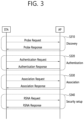
- FIG. 3 illustrates a general link setup process
- a STA may perform a network discovery operation.
- the network discovery operation may include a scanning operation of the STA. That is, to access a network, the STA needs to discover a participating network.
- the STA needs to identify a compatible network before participating in a wireless network, and a process of identifying a network present in a particular area is referred to as scanning.
- Scanning methods include active scanning and passive scanning.
- FIG. 3 illustrates a network discovery operation including an active scanning process.
- a STA performing scanning transmits a probe request frame and waits for a response to the probe request frame in order to identify which AP is present around while moving to channels.
- a responder transmits a probe response frame as a response to the probe request frame to the STA having transmitted the probe request frame.
- the responder may be a STA that transmits the last beacon frame in a BSS of a channel being scanned.
- the AP since an AP transmits a beacon frame, the AP is the responder.
- the responder is not fixed.
- the STA when the STA transmits a probe request frame via channel 1 and receives a probe response frame via channel 1, the STA may store BSS-related information included in the received probe response frame, may move to the next channel (e.g., channel 2), and may perform scanning (e.g., transmits a probe request and receives a probe response via channel 2) by the same method.
- the next channel e.g., channel 2
- scanning e.g., transmits a probe request and receives a probe response via channel 2 by the same method.
- scanning may be performed by a passive scanning method.
- a STA performing scanning may wait for a beacon frame while moving to channels.
- a beacon frame is one of management frames in IEEE 802.11 and is periodically transmitted to indicate the presence of a wireless network and to enable the STA performing scanning to find the wireless network and to participate in the wireless network.
- an AP serves to periodically transmit a beacon frame.
- STAs in the IBSS transmit a beacon frame in turns.
- the STA performing scanning stores information about a BSS included in the beacon frame and records beacon frame information in each channel while moving to another channel.
- the STA having received the beacon frame may store BSS-related information included in the received beacon frame, may move to the next channel, and may perform scanning in the next channel by the same method.
- the STA may perform an authentication process in S 320 .
- the authentication process may be referred to as a first authentication process to be clearly distinguished from the following security setup operation in S 340 .
- the authentication process in S 320 may include a process in which the STA transmits an authentication request frame to the AP and the AP transmits an authentication response frame to the STA in response.
- the authentication frames used for an authentication request/response are management frames.
- the authentication frames may include information about an authentication algorithm number, an authentication transaction sequence number, a status code, a challenge text, a robust security network (RSN), and a finite cyclic group.
- RSN robust security network
- the STA may transmit the authentication request frame to the AP.
- the AP may determine whether to allow the authentication of the STA based on the information included in the received authentication request frame.
- the AP may provide the authentication processing result to the STA via the authentication response frame.
- the STA may perform an association process in S 330 .
- the association process includes a process in which the STA transmits an association request frame to the AP and the AP transmits an association response frame to the STA in response.
- the association request frame may include, for example, information about various capabilities, a beacon listen interval, a service set identifier (SSID), a supported rate, a supported channel, RSN, a mobility domain, a supported operating class, a traffic indication map (TIM) broadcast request, and an interworking service capability.
- SSID service set identifier
- TIM traffic indication map
- the association response frame may include, for example, information about various capabilities, a status code, an association ID (AID), a supported rate, an enhanced distributed channel access (EDCA) parameter set, a received channel power indicator (RCPI), a received signal-to-noise indicator (RSNI), a mobility domain, a timeout interval (association comeback time), an overlapping BSS scanning parameter, a TIM broadcast response, and a QoS map.
- AID association ID
- EDCA enhanced distributed channel access
- RCPI received channel power indicator
- RSNI received signal-to-noise indicator
- mobility domain a timeout interval (association comeback time)
- association comeback time an overlapping BSS scanning parameter
- a TIM broadcast response and a QoS map.
- the STA may perform a security setup process.
- the security setup process in S 340 may include a process of setting up a private key through four-way handshaking, for example, through an extensible authentication protocol over LAN (EAPOL) frame.
- EAPOL extensible authentication protocol over LAN
- FIG. 4 illustrates an example of a PPDU used in an IEEE standard.
- an LTF and a STF include a training signal
- a SIG-A and a SIG-B include control information for a receiving STA
- a data field includes user data corresponding to a PSDU (MAC PDU/aggregated MAC PDU).
- PSDU MAC PDU/aggregated MAC PDU
- FIG. 4 also includes an example of an HE PPDU according to IEEE 802.11ax.
- the HE PPDU according to FIG. 4 is an illustrative PPDU for multiple users.
- An HE-SIG-B may be included only in a PPDU for multiple users, and an HE-SIG-B may be omitted in a PPDU for a single user.
- the HE-PPDU for multiple users may include a legacy-short training field (L-STF), a legacy-long training field (L-LTF), a legacy-signal (L-SIG), a high efficiency-signal A (HE-SIG A), a high efficiency-signal-B (HE-SIG B), a high efficiency-short training field (HE-STF), a high efficiency-long training field (HE-LTF), a data field (alternatively, an MAC payload), and a packet extension (PE) field.
- L-STF legacy-short training field
- L-LTF legacy-long training field
- L-SIG legacy-signal
- HE-SIG A high efficiency-signal A
- HE-SIG B high efficiency-short training field
- HE-LTF high efficiency-long training field
- PE packet extension
- the respective fields may be transmitted for illustrated time periods (i.e., 4 or 8 ⁇ s).
- An RU may include a plurality of subcarriers (or tones).
- An RU may be used to transmit a signal to a plurality of STAs according to OFDMA. Further, an RU may also be defined to transmit a signal to one STA.
- An RU may be used for an STF, an LTF, a data field, or the like.
- FIG. 5 illustrates a layout of resource units (RUs) used in a band of 20 MHz.
- resource units corresponding to different numbers of tones (i.e., subcarriers) may be used to form some fields of an HE-PPDU.
- resources may be allocated in illustrated RUs for an HE-STF, an HE-LTF, and a data field.
- a 26-unit i.e., a unit corresponding to 26 tones
- Six tones may be used for a guard band in the leftmost band of the 20 MHz band, and five tones may be used for a guard band in the rightmost band of the 20 MHz band.
- seven DC tones may be inserted in a center band, that is, a DC band, and a 26-unit corresponding to 13 tones on each of the left and right sides of the DC band may be disposed.
- a 26-unit, a 52-unit, and a 106-unit may be allocated to other bands. Each unit may be allocated for a receiving STA, that is, a user.
- the layout of the RUs in FIG. 5 may be used not only for a multiple users (MUs) but also for a single user (SU), in which case one 242-unit may be used and three DC tones may be inserted as illustrated in the lowermost part of FIG. 5 .
- FIG. 5 proposes RUs having various sizes, that is, a 26-RU, a 52-RU, a 106-RU, and a 242-RU, specific sizes of RUs may be extended or increased. Therefore, the present embodiment is not limited to the specific size of each RU (i.e., the number of corresponding tones).
- FIG. 6 illustrates a layout of RUs used in a band of 40 MHz.
- a 26-RU, a 52-RU, a 106-RU, a 242-RU, a 484-RU, and the like may be used in an example of FIG. 6 .
- five DC tones may be inserted in a center frequency, 12 tones may be used for a guard band in the leftmost band of the 40 MHz band, and 11 tones may be used for a guard band in the rightmost band of the 40 MHz band.
- a 484-RU may be used.
- the specific number of RUs may be changed similarly to FIG. 5 .
- FIG. 7 illustrates a layout of RUs used in a band of 80 MHz.
- a 26-RU, a 52-RU, a 106-RU, a 242-RU, a 484-RU, a 996-RU, and the like may be used in an example of FIG. 7 .
- seven DC tones may be inserted in the center frequency, 12 tones may be used for a guard band in the leftmost band of the 80 MHz band, and 11 tones may be used for a guard band in the rightmost band of the 80 MHz band.
- a 26-RU corresponding to 13 tones on each of the left and right sides of the DC band may be used.
- a 996-RU may be used, in which case five DC tones may be inserted.
- the RU described in the present specification may be used in uplink (UL) communication and downlink (DL) communication.
- a transmitting STA e.g., an AP
- the first STA may transmit a first trigger-based PPDU based on the first RU
- the second STA may transmit a second trigger-based PPDU based on the second RU.
- the first/second trigger-based PPDU is transmitted to the AP at the same (or overlapped) time period.
- the transmitting STA may allocate the first RU (e.g., 26/52/106/242-RU, etc.) to the first STA, and may allocate the second RU (e.g., 26/52/106/242-RU, etc.) to the second STA. That is, the transmitting STA (e.g., AP) may transmit HE-STF, HE-LTF, and Data fields for the first STA through the first RU in one MU PPDU, and may transmit HE-STF, HE-LTF, and Data fields for the second STA through the second RU.
- the transmitting STA e.g., AP
- Information related to a layout of the RU may be signaled through HE-SIG-B.
- FIG. 8 illustrates a structure of an HE-SIG-B field.
- an HE-SIG-B field 810 includes a common field 820 and a user-specific field 830 .
- the common field 820 may include information commonly applied to all users (i.e., user STAs) which receive SIG-B.
- the user-specific field 830 may be called a user-specific control field. When the SIG-B is transferred to a plurality of users, the user-specific field 830 may be applied only any one of the plurality of users.
- the common field 820 and the user-specific field 830 may be separately encoded.
- the common field 820 may include RU allocation information of N*8 bits.
- the RU allocation information may include information related to a location of an RU.
- the RU allocation information may include information related to a specific frequency band to which a specific RU (26-RU/52-RU/106-RU) is arranged.
- up to nine 26-RUs may be allocated to the 20 MHz channel.
- the RU allocation information of the common field 820 is set to “00000000” as shown in Table 1
- the nine 26-RUs may be allocated to a corresponding channel (i.e., 20 MHz).
- the RU allocation information of the common field 820 is set to “00000001” as shown in Table 1
- seven 26-RUs and one 52-RU are arranged in a corresponding channel. That is, in the example of FIG. 5 , the 52-RU may be allocated to the rightmost side, and the seven 26-RUs may be allocated to the left thereof.
- Table 1 shows only some of RU locations capable of displaying the RU allocation information.
- the RU allocation information may include an example of Table 2 below.
- “01000y2y1y0” relates to an example in which a 106-RU is allocated to the leftmost side of the 20 MHz channel, and five 26-RUs are allocated to the right side thereof.
- a plurality of STAs e.g., user-STAs
- a MU-MIMO scheme e.g., up to 8 STAs (e.g., user-STAs) may be allocated to the 106-RU, and the number of STAs (e.g., user-STAs) allocated to the 106-RU is determined based on 3-bit information (y2y1y0). For example, when the 3-bit information (y2y1y0) is set to N, the number of STAs (e.g., user-STAs) allocated to the 106-RU based on the MU-MIMO scheme may be N+1.
- a plurality of STAs (e.g., user STAs) different from each other may be allocated to a plurality of RUs.
- the plurality of STAs (e.g., user STAs) may be allocated to one or more RUs having at least a specific size (e.g., 106 subcarriers), based on the MU-MIMO scheme.
- the user-specific field 830 may include a plurality of user fields.
- the number of STAs (e.g., user STAs) allocated to a specific channel may be determined based on the RU allocation information of the common field 820 . For example, when the RU allocation information of the common field 820 is “00000000”, one user STA may be allocated to each of nine 26-RUs (e.g., nine user STAs may be allocated). That is, up to 9 user STAs may be allocated to a specific channel through an OFDMA scheme. In other words, up to 9 user STAs may be allocated to a specific channel through a non-MU-MIMO scheme.
- RU allocation when RU allocation is set to “01000y2y1y0”, a plurality of STAs may be allocated to the 106-RU arranged at the leftmost side through the MU-MIMO scheme, and five user STAs may be allocated to five 26-RUs arranged to the right side thereof through the non-MU MIMO scheme. This case is specified through an example of FIG. 9 .
- FIG. 9 illustrates an example in which a plurality of user STAs are allocated to the same RU through a MU-MIMO scheme.
- a 106-RU may be allocated to the leftmost side of a specific channel, and five 26-RUs may be allocated to the right side thereof.
- three user STAs may be allocated to the 106-RU through the MU-MIMO scheme.
- the user-specific field 830 of HE-SIG-B may include eight user fields.
- the eight user fields may be expressed in the order shown in FIG. 9 .
- two user fields may be implemented with one user block field.
- the user fields shown in FIG. 8 and FIG. 9 may be configured based on two formats. That is, a user field related to a MU-MIMO scheme may be configured in a first format, and a user field related to a non-MIMO scheme may be configured in a second format. Referring to the example of FIG. 9 , a user field 1 to a user field 3 may be based on the first format, and a user field 4 to a user field 8 may be based on the second format.
- the first format or the second format may include bit information of the same length (e.g., 21 bits).
- Each user field may have the same size (e.g., 21 bits).
- the user field of the first format (the first of the MU-MIMO scheme) may be configured as follows.
- a first bit (i.e., B0-B10) in the user field may include identification information (e.g., STA-ID, partial AID, etc.) of a user STA to which a corresponding user field is allocated.
- a second bit (i.e., B11-B14) in the user field may include information related to a spatial configuration.
- an example of the second bit (i.e., B11-B14) may be as shown in Table 3 and Table 4 below.
- information (i.e., the second bit, B11-B14) related to the number of spatial streams for the user STA may consist of 4 bits.
- the information (i.e., the second bit, B11-B14) on the number of spatial streams for the user STA may support up to eight spatial streams.
- the information (i.e., the second bit, B11-B14) on the number of spatial streams for the user STA may support up to four spatial streams for one user STA.
- a third bit (i.e., B15-18) in the user field may include modulation and coding scheme (MCS) information.
- MCS modulation and coding scheme
- the MCS information may be applied to a data field in a PPDU including corresponding SIG-B.
- An MCS, MCS information, an MCS index, an MCS field, or the like used in the present specification may be indicated by an index value.
- the MCS information may be indicated by an index 0 to an index 11.
- the MCS information may include information related to a constellation modulation type (e.g., BPSK, QPSK, 16-QAM, 64-QAM, 256-QAM, 1024-QAM, etc.) and information related to a coding rate (e.g., 1/2, 2/3, 3/4, 5/6e, etc.).
- Information related to a channel coding type e.g., LCC or LDPC
- LCC long-coding code
- a fourth bit (i.e., B19) in the user field may be a reserved field.
- a fifth bit (i.e., B20) in the user field may include information related to a coding type (e.g., BCC or LDPC). That is, the fifth bit (i.e., B20) may include information related to a type (e.g., BCC or LDPC) of channel coding applied to the data field in the PPDU including the corresponding SIG-B.
- a coding type e.g., BCC or LDPC
- the aforementioned example relates to the user field of the first format (the format of the MU-MIMO scheme).
- An example of the user field of the second format (the format of the non-MU-MIMO scheme) is as follows.
- a first bit (e.g., B0-B10) in the user field of the second format may include identification information of a user STA.
- a second bit (e.g., B11-B13) in the user field of the second format may include information related to the number of spatial streams applied to a corresponding RU.
- a third bit (e.g., B14) in the user field of the second format may include information related to whether a beamforming steering matrix is applied.
- a fourth bit (e.g., B15-B18) in the user field of the second format may include modulation and coding scheme (MCS) information.
- MCS modulation and coding scheme
- a fifth bit (e.g., B19) in the user field of the second format may include information related to whether dual carrier modulation (DCM) is applied.
- a sixth bit (i.e., B20) in the user field of the second format may include information related to a coding type (e.g., BCC or LDPC).
- FIG. 10 illustrates an operation based on UL-MU.
- a transmitting STA e.g., an AP
- may perform channel access through contending e.g., a backoff operation
- a trigger-based (TB) PPDU is transmitted after a delay corresponding to SIFS.
- TB PPDUs 1041 and 1042 may be transmitted at the same time period, and may be transmitted from a plurality of STAs (e.g., user STAs) having AIDs indicated in the trigger frame 1030 .
- An ACK frame 1050 for the TB PPDU may be implemented in various forms.
- a specific feature of the trigger frame is described with reference to FIG. 11 to FIG. 13 .
- an orthogonal frequency division multiple access (OFDMA) scheme or a MU MIMO scheme may be used, and the OFDMA and MU-MIMO schemes may be simultaneously used.
- OFDMA orthogonal frequency division multiple access
- MU MIMO MU MIMO
- FIG. 11 illustrates an example of a trigger frame.
- the trigger frame of FIG. 11 allocates a resource for uplink multiple-user (MU) transmission, and may be transmitted, for example, from an AP.
- the trigger frame may be configured of a MAC frame, and may be included in a PPDU.
- Each field shown in FIG. 11 may be partially omitted, and another field may be added. In addition, a length of each field may be changed to be different from that shown in the figure.
- a frame control field 1110 of FIG. 11 may include information related to a MAC protocol version and extra additional control information.
- a duration field 1120 may include time information for NAV configuration or information related to an identifier (e.g., AID) of a STA.
- an RA field 1130 may include address information of a receiving STA of a corresponding trigger frame, and may be optionally omitted.
- a TA field 1140 may include address information of a STA (e.g., an AP) which transmits the corresponding trigger frame.
- a common information field 1150 includes common control information applied to the receiving STA which receives the corresponding trigger frame. For example, a field indicating a length of an L-SIG field of an uplink PPDU transmitted in response to the corresponding trigger frame or information for controlling content of a SIG-A field (i.e., HE-SIG-A field) of the uplink PPDU transmitted in response to the corresponding trigger frame may be included.
- common control information information related to a length of a CP of the uplink PPDU transmitted in response to the corresponding trigger frame or information related to a length of an LTF field may be included.
- per user information fields 1160 # 1 to 1160 #N corresponding to the number of receiving STAs which receive the trigger frame of FIG. 11 are preferably included.
- the per user information field may also be called an “allocation field”.
- the trigger frame of FIG. 11 may include a padding field 1170 and a frame check sequence field 1180 .
- Each of the per user information fields 1160 # 1 to 1160 #N shown in FIG. 11 may include a plurality of subfields.
- FIG. 12 illustrates an example of a common information field of a trigger frame.
- a subfield of FIG. 12 may be partially omitted, and an extra subfield may be added.
- a length of each subfield illustrated may be changed.
- a length field 1210 illustrated has the same value as a length field of an L-SIG field of an uplink PPDU transmitted in response to a corresponding trigger frame, and a length field of the L-SIG field of the uplink PPDU indicates a length of the uplink PPDU.
- the length field 1210 of the trigger frame may be used to indicate the length of the corresponding uplink PPDU.
- a cascade identifier field 1220 indicates whether a cascade operation is performed.
- the cascade operation implies that downlink MU transmission and uplink MU transmission are performed together in the same TXOP. That is, it implies that downlink MU transmission is performed and thereafter uplink MU transmission is performed after a pre-set time (e.g., SIFS).
- a pre-set time e.g., SIFS.
- only one transmitting device e.g., AP
- a plurality of transmitting devices e.g., non-APs
- a CS request field 1230 indicates whether a wireless medium state or a NAV or the like is necessarily considered in a situation where a receiving device which has received a corresponding trigger frame transmits a corresponding uplink PPDU.
- An HE-SIG-A information field 1240 may include information for controlling content of a SIG-A field (i.e., HE-SIG-A field) of the uplink PPDU in response to the corresponding trigger frame.
- a CP and LTF type field 1250 may include information related to a CP length and LTF length of the uplink PPDU transmitted in response to the corresponding trigger frame.
- a trigger type field 1260 may indicate a purpose of using the corresponding trigger frame, for example, typical triggering, triggering for beamforming, a request for block ACK/NACK, or the like.
- the trigger type field 1260 of the trigger frame in the present specification indicates a trigger frame of a basic type for typical triggering.
- the trigger frame of the basic type may be referred to as a basic trigger frame.
- FIG. 13 illustrates an example of a subfield included in a per user information field.
- a user information field 1300 of FIG. 13 may be understood as any one of the per user information fields 1160 # 1 to 1160 #N mentioned above with reference to FIG. 11 .
- a subfield included in the user information field 1300 of FIG. 13 may be partially omitted, and an extra subfield may be added.
- a length of each subfield illustrated may be changed.
- a user identifier field 1310 of FIG. 13 indicates an identifier of a STA (i.e., receiving STA) corresponding to per user information.
- An example of the identifier may be the entirety or part of an association identifier (AID) value of the receiving STA.
- an RU allocation field 1320 may be included. That is, when the receiving STA identified through the user identifier field 1310 transmits a TB PPDU in response to the trigger frame, the TB PPDU is transmitted through an RU indicated by the RU allocation field 1320 .
- the RU indicated by the RU allocation field 1320 may be an RU shown in FIG. 5 , FIG. 6 , and FIG. 7 .
- the subfield of FIG. 13 may include a coding type field 1330 .
- the coding type field 1330 may indicate a coding type of the TB PPDU. For example, when BCC coding is applied to the TB PPDU, the coding type field 1330 may be set to ‘1’, and when LDPC coding is applied, the coding type field 1330 may be set to ‘0’.
- the subfield of FIG. 13 may include an MCS field 1340 .
- the MCS field 1340 may indicate an MCS scheme applied to the TB PPDU. For example, when BCC coding is applied to the TB PPDU, the coding type field 1330 may be set to ‘1’, and when LDPC coding is applied, the coding type field 1330 may be set to ‘0’.
- FIG. 14 describes a technical feature of the UORA scheme.
- a transmitting STA may allocate six RU resources through a trigger frame as shown in FIG. 14 .
- the AP may allocate a 1st RU resource (AID 0, RU 1), a 2nd RU resource (AID 0, RU 2), a 3rd RU resource (AID 0, RU 3), a 4th RU resource (AID 2045, RU 4), a 5th RU resource (AID 2045, RU 5), and a 6th RU resource (AID 3, RU 6).
- Information related to the AID 0, AID 3, or AID 2045 may be included, for example, in the user identifier field 1310 of FIG. 13 .
- Information related to the RU 1 to RU 6 may be included, for example, in the RU allocation field 1320 of FIG. 13 .
- the 1st to 3rd RU resources of FIG. 14 may be used as a UORA resource for the associated STA
- the 4th and 5th RU resources of FIG. 14 may be used as a UORA resource for the un-associated STA
- the 6th RU resource of FIG. 14 may be used as a typical resource for UL MU.
- an OFDMA random access backoff (OBO) of a STA1 is decreased to 0, and the STA1 randomly selects the 2nd RU resource (AID 0, RU 2).
- OBO counter of a STA2/3 is greater than 0, an uplink resource is not allocated to the STA2/3.
- a resource of the RU 6 is allocated without backoff.
- the STA1 of FIG. 14 is an associated STA
- the total number of eligible RA RUs for the STA1 is 3 (RU 1, RU 2, and RU 3), and thus the STA1 decreases an OBO counter by 3 so that the OBO counter becomes 0.
- the STA2 of FIG. 14 is an associated STA
- the total number of eligible RA RUs for the STA2 is 3 (RU 1, RU 2, and RU 3), and thus the STA2 decreases the OBO counter by 3 but the OBO counter is greater than 0.
- the STA3 of FIG. 14 is an un-associated STA
- the total number of eligible RA RUs for the STA3 is 2 (RU 4, RU 5), and thus the STA3 decreases the OBO counter by 2 but the OBO counter is greater than 0.
- FIG. 15 illustrates an example of a channel used/supported/defined within a 2.4 GHz band.
- the 2.4 GHz band may be called in other terms such as a first band.
- the 2.4 GHz band may imply a frequency domain in which channels of which a center frequency is close to 2.4 GHz (e.g., channels of which a center frequency is located within 2.4 to 2.5 GHz) are used/supported/defined.
- a plurality of 20 MHz channels may be included in the 2.4 GHz band.
- 20 MHz within the 2.4 GHz may have a plurality of channel indices (e.g., an index 1 to an index 14).
- a center frequency of a 20 MHz channel to which a channel index 1 is allocated may be 2.412 GHz
- a center frequency of a 20 MHz channel to which a channel index 2 is allocated may be 2.417 GHz
- a center frequency of a 20 MHz channel to which a channel index N is allocated may be (2.407+0.005*N) GHz.
- the channel index may be called in various terms such as a channel number or the like. Specific numerical values of the channel index and center frequency may be changed.
- FIG. 15 exemplifies 4 channels within a 2.4 GHz band.
- Each of 1st to 4th frequency domains 1510 to 1540 shown herein may include one channel.
- the 1st frequency domain 1510 may include a channel 1 (a 20 MHz channel having an index 1).
- a center frequency of the channel 1 may be set to 2412 MHz.
- the 2nd frequency domain 1520 may include a channel 6.
- a center frequency of the channel 6 may be set to 2437 MHz.
- the 3rd frequency domain 1530 may include a channel 11.
- a center frequency of the channel 11 may be set to 2462 MHz.
- the 4th frequency domain 1540 may include a channel 14. In this case, a center frequency of the channel 14 may be set to 2484 MHz.
- FIG. 16 illustrates an example of a channel used/supported/defined within a 5 GHz band.
- the 5 GHz band may be called in other terms such as a second band or the like.
- the 5 GHz band may imply a frequency domain in which channels of which a center frequency is greater than or equal to 5 GHz and less than 6 GHz (or less than 5.9 GHz) are used/supported/defined.
- the 5 GHz band may include a plurality of channels between 4.5 GHz and 5.5 GHz. A specific numerical value shown in FIG. 16 may be changed.
- a plurality of channels within the 5 GHz band include an unlicensed national information infrastructure (UNII)-1, a UNII-2, a UNII-3, and an ISM.
- the INII-1 may be called UNII Low.
- the UNII-2 may include a frequency domain called UNII Mid and UNII-2Extended.
- the UNII-3 may be called UNII-Upper.
- a plurality of channels may be configured within the 5 GHz band, and a bandwidth of each channel may be variously set to, for example, 20 MHz, 40 MHz, 80 MHz, 160 MHz, or the like.
- 5170 MHz to 5330 MHz frequency domains/ranges within the UNII-1 and UNII-2 may be divided into eight 20 MHz channels.
- the 5170 MHz to 5330 MHz frequency domains/ranges may be divided into four channels through a 40 MHz frequency domain.
- the 5170 MHz to 5330 MHz frequency domains/ranges may be divided into two channels through an 80 MHz frequency domain.
- the 5170 MHz to 5330 MHz frequency domains/ranges may be divided into one channel through a 160 MHz frequency domain.
- FIG. 17 illustrates an example of a channel used/supported/defined within a 6 GHz band.
- the 6 GHz band may be called in other terms such as a third band or the like.
- the 6 GHz band may imply a frequency domain in which channels of which a center frequency is greater than or equal to 5.9 GHz are used/supported/defined.
- a specific numerical value shown in FIG. 17 may be changed.
- the 20 MHz channel of FIG. 17 may be defined starting from 5.940 GHz.
- the leftmost channel may have an index 1 (or a channel index, a channel number, etc.), and 5.945 GHz may be assigned as a center frequency. That is, a center frequency of a channel of an index N may be determined as (5.940+0.005*N) GHz.
- an index (or channel number) of the 2 MHz channel of FIG. 17 may be 1, 5, 9, 13, 17, 21, 25, 29, 33, 37, 41, 45, 49, 53, 57, 61, 65, 69, 73, 77, 81, 85, 89, 93, 97, 101, 105, 109, 113, 117, 121, 125, 129, 133, 137, 141, 145, 149, 153, 157, 161, 165, 169, 173, 177, 181, 185, 189, 193, 197, 201, 205, 209, 213, 217, 221, 225, 229, 233.
- an index of the 40 MHz channel of FIG. 17 may be 3, 11, 19, 27, 35, 43, 51, 59, 67, 75, 83, 91, 99, 107, 115, 123, 131, 139, 147, 155, 163, 171, 179, 187, 195, 203, 211, 219, 227.
- a 240 MHz channel or a 320 MHz channel may be additionally added.
- FIG. 18 illustrates an example of a PPDU used in the present specification.
- the PPDU of FIG. 18 may be called in various terms such as an EHT PPDU, a TX PPDU, an RX PPDU, a first type or N-th type PPDU, or the like.
- the PPDU or the EHT PPDU may be called in various terms such as a TX PPDU, a RX PPDU, a first type or N-th type PPDU, or the like.
- the EHT PPDU may be used in an EHT system and/or a new WLAN system enhanced from the EHT system.
- the PPDU of FIG. 18 may represent some or all of the PPDU types used in the EHT system.
- the example of FIG. 18 may be used for both a single-user (SU) mode and a multi-user (MU) mode, or may be used only for the SU mode, or may be used only for the MU mode.
- a trigger-based PPDU (TB) on the EHT system may be separately defined or configured based on the example of FIG. 18 .
- the trigger frame described through at least one of FIGS. 10 to 14 and the UL-MU operation (e.g., the TB PPDU transmission operation) started by the trigger frame may be directly applied to the EHT system.
- an L-STF to an EHT-LTF may be called a preamble or a physical preamble, and may be generated/transmitted/received/obtained/decoded in a physical layer.
- a subcarrier spacing of the L-STF, L-LTF, L-SIG, RL-SIG, U-SIG, and EHT-SIG fields of FIG. 18 may be determined as 312.5 kHz, and a subcarrier spacing of the EHT-STF, EHT-LTF, and Data fields may be determined as 78.125 kHz.
- a tone index (or subcarrier index) of the L-STF, L-LTF, L-SIG, RL-SIG, U-SIG, and EHT-SIG fields may be expressed in unit of 312.5 kHz
- a tone index (or subcarrier index) of the EHT-STF, EHT-LTF, and Data fields may be expressed in unit of 78.125 kHz.
- the L-LTF and the L-STF may be the same as those in the conventional fields.
- the L-SIG field of FIG. 18 may include, for example, bit information of 24 bits.
- the 24-bit information may include a rate field of 4 bits, a reserved bit of 1 bit, a length field of 12 bits, a parity bit of 1 bit, and a tail bit of 6 bits.
- the length field of 12 bits may include information related to a length or time duration of a PPDU.
- the length field of 12 bits may be determined based on a type of the PPDU. For example, when the PPDU is a non-HT, HT, VHT PPDU or an EHT PPDU, a value of the length field may be determined as a multiple of 3.
- the value of the length field may be determined as “a multiple of 3”+1 or “a multiple of 3”+2.
- the value of the length field may be determined as a multiple of 3
- the value of the length field may be determined as “a multiple of 3”+1 or “a multiple of 3”+2.
- the transmitting STA may apply BCC encoding based on a 1/2 coding rate to the 24-bit information of the L-SIG field. Thereafter, the transmitting STA may obtain a BCC coding bit of 48 bits. BPSK modulation may be applied to the 48-bit coding bit, thereby generating 48 BPSK symbols. The transmitting STA may map the 48 BPSK symbols to positions except for a pilot subcarrier ⁇ subcarrier index ⁇ 21, ⁇ 7, +7, +21 ⁇ and a DC subcarrier ⁇ subcarrier index 0 ⁇ .
- the 48 BPSK symbols may be mapped to subcarrier indices ⁇ 26 to ⁇ 22, ⁇ 20 to ⁇ 8, ⁇ 6 to ⁇ 1, +1 to +6, +8 to +20, and +22 to +26.
- the transmitting STA may additionally map a signal of ⁇ 1, ⁇ 1, ⁇ 1, 1 ⁇ to a subcarrier index ⁇ 28, ⁇ 27, +27, +28 ⁇ .
- the aforementioned signal may be used for channel estimation on a frequency domain corresponding to ⁇ 28, ⁇ 27, +27, +28 ⁇ .
- the transmitting STA may generate an RL-SIG generated in the same manner as the L-SIG.
- BPSK modulation may be applied to the RL-SIG.
- the receiving STA may know that the RX PPDU is the HE PPDU or the EHT PPDU, based on the presence of the RL-SIG.
- a universal SIG may be inserted after the RL-SIG of FIG. 18 .
- the U-SIG may be called in various terms such as a first SIG field, a first SIG, a first type SIG, a control signal, a control signal field, a first (type) control signal, or the like.
- the U-SIG may include information of N bits, and may include information for identifying a type of the EHT PPDU.
- the U-SIG may be configured based on two symbols (e.g., two contiguous OFDM symbols). Each symbol (e.g., OFDM symbol) for the U-SIG may have a duration of 4 ⁇ s.
- Each symbol of the U-SIG may be used to transmit the 26-bit information. For example, each symbol of the U-SIG may be transmitted/received based on 52 data tomes and 4 pilot tones.
- A-bit information (e.g., 52 un-coded bits) may be transmitted.
- a first symbol of the U-SIG may transmit first X-bit information (e.g., 26 un-coded bits) of the A-bit information, and a second symbol of the U-SIG may transmit the remaining Y-bit information (e.g. 26 un-coded bits) of the A-bit information.
- the transmitting STA may obtain 26 un-coded bits included in each U-SIG symbol.
- the transmitting STA may perform BPSK modulation on the interleaved 52-coded bits to generate 52 BPSK symbols to be allocated to each U-SIG symbol.
- One U-SIG symbol may be transmitted based on 65 tones (subcarriers) from a subcarrier index ⁇ 28 to a subcarrier index +28, except for a DC index 0.
- the 52 BPSK symbols generated by the transmitting STA may be transmitted based on the remaining tones (subcarriers) except for pilot tones, i.e., tones ⁇ 21, ⁇ 7, +7, +21.
- the A-bit information (e.g., 52 un-coded bits) generated by the U-SIG may include a CRC field (e.g., a field having a length of 4 bits) and a tail field (e.g., a field having a length of 6 bits).
- the CRC field and the tail field may be transmitted through the second symbol of the U-SIG.
- the CRC field may be generated based on 26 bits allocated to the first symbol of the U-SIG and the remaining 16 bits except for the CRC/tail fields in the second symbol, and may be generated based on the conventional CRC calculation algorithm.
- the tail field may be used to terminate trellis of a convolutional decoder, and may be set to, for example, “000000”.
- the A-bit information (e.g., 52 un-coded bits) transmitted by the U-SIG (or U-SIG field) may be divided into version-independent bits and version-dependent bits.
- the version-independent bits may have a fixed or variable size.
- the version-independent bits may be allocated only to the first symbol of the U-SIG, or the version-independent bits may be allocated to both of the first and second symbols of the U-SIG.
- the version-independent bits and the version-dependent bits may be called in various terms such as a first control bit, a second control bit, or the like.
- the version-independent bits of the U-SIG may include a PHY version identifier of 3 bits.
- the PHY version identifier of 3 bits may include information related to a PHY version of a TX/RX PPDU.
- a first value of the PHY version identifier of 3 bits may indicate that the TX/RX PPDU is an EHT PPDU.
- the PHY version identifier of 3 bits may be set to a first value.
- the receiving STA may determine that the RX PPDU is the EHT PPDU, based on the PHY version identifier having the first value.
- the version-independent bits of the U-SIG may include a UL/DL flag field of 1 bit.
- a first value of the UL/DL flag field of 1 bit relates to UL communication, and a second value of the UL/DL flag field relates to DL communication.
- the version-independent bits of the U-SIG may include information related to a TXOP length and information related to a BSS color ID.
- the EHT PPDU when the EHT PPDU is divided into various types (e.g., various types such as an EHT PPDU related to an SU mode, an EHT PPDU related to a MU mode, an EHT PPDU related to a TB mode, an EHT PPDU related to extended range transmission, or the like), information related to the type of the EHT PPDU may be included in the version-dependent bits of the U-SIG.
- various types e.g., various types such as an EHT PPDU related to an SU mode, an EHT PPDU related to a MU mode, an EHT PPDU related to a TB mode, an EHT PPDU related to extended range transmission, or the like
- information related to the type of the EHT PPDU may be included in the version-dependent bits of the U-SIG.
- the U-SIG may include: 1) a bandwidth field including information related to a bandwidth; 2) a field including information related to an MCS scheme applied to EHT-SIG; 3) an indication field including information related to whether a dual subcarrier modulation (DCM) scheme is applied to EHT-SIG; 4) a field including information related to the number of symbol used for EHT-SIG; 5) a field including information related to whether the EHT-SIG is generated across a full band; 6) a field including information related to a type of EHT-LTF/STF; and 7) information related to a field indicating an EHT-LTF length and a CP length.
- DCM dual subcarrier modulation
- Preamble puncturing may be applied to the PPDU of FIG. 18 .
- the preamble puncturing implies that puncturing is applied to part (e.g., a secondary 20 MHz band) of the full band.
- a STA may apply puncturing to the secondary 20 MHz band out of the 80 MHz band, and may transmit a PPDU only through a primary 20 MHz band and a secondary 40 MHz band.
- a pattern of the preamble puncturing may be configured in advance. For example, when a first puncturing pattern is applied, puncturing may be applied only to the secondary 20 MHz band within the 80 MHz band. For example, when a second puncturing pattern is applied, puncturing may be applied to only any one of two secondary 20 MHz bands included in the secondary 40 MHz band within the 80 MHz band. For example, when a third puncturing pattern is applied, puncturing may be applied to only the secondary 20 MHz band included in the primary 80 MHz band within the 160 MHz band (or 80+80 MHz band).
- puncturing may be applied to at least one 20 MHz channel not belonging to a primary 40 MHz band in the presence of the primary 40 MHz band included in the 80 MHz band within the 160 MHz band (or 80+80 MHz band).
- Information related to the preamble puncturing applied to the PPDU may be included in U-SIG and/or EHT-SIG.
- a first field of the U-SIG may include information related to a contiguous bandwidth
- second field of the U-SIG may include information related to the preamble puncturing applied to the PPDU.
- the U-SIG and the EHT-SIG may include the information related to the preamble puncturing, based on the following method.
- the U-SIG may be configured individually in unit of 80 MHz.
- the PPDU may include a first U-SIG for a first 80 MHz band and a second U-SIG for a second 80 MHz band.
- a first field of the first U-SIG may include information related to a 160 MHz bandwidth
- a second field of the first U-SIG may include information related to a preamble puncturing (i.e., information related to a preamble puncturing pattern) applied to the first 80 MHz band
- a first field of the second U-SIG may include information related to a 160 MHz bandwidth
- a second field of the second U-SIG may include information related to a preamble puncturing (i.e., information related to a preamble puncturing pattern) applied to the second 80 MHz band.
- an EHT-SIG contiguous to the first U-SIG may include information related to a preamble puncturing applied to the second 80 MHz band (i.e., information related to a preamble puncturing pattern), and an EHT-SIG contiguous to the second U-SIG may include information related to a preamble puncturing (i.e., information related to a preamble puncturing pattern) applied to the first 80 MHz band.
- the U-SIG and the EHT-SIG may include the information related to the preamble puncturing, based on the following method.
- the U-SIG may include information related to a preamble puncturing (i.e., information related to a preamble puncturing pattern) for all bands. That is, the EHT-SIG may not include the information related to the preamble puncturing, and only the U-SIG may include the information related to the preamble puncturing (i.e., the information related to the preamble puncturing pattern).
- the U-SIG may be configured in unit of 20 MHz. For example, when an 80 MHz PPDU is configured, the U-SIG may be duplicated. That is, four identical U-SIGs may be included in the 80 MHz PPDU. PPDUs exceeding an 80 MHz bandwidth may include different U-SIGs.
- the EHT-SIG of FIG. 18 may include the technical feature of the HE-SIG-B shown in the examples of FIGS. 8 to 9 as it is.
- the EHT-SIG may be referred to by various names such as a second SIG field, a second SIG, a second type SIG, a control signal, a control signal field, and a second (type) control signal.
- the EHT-SIG may include N-bit information (e.g., 1-bit information) regarding whether the EHT-PPDU supports the SU mode or the MU mode.
- N-bit information e.g., 1-bit information
- the EHT-SIG may be configured based on various MCS schemes. As described above, information related to an MCS scheme applied to the EHT-SIG may be included in U-SIG.
- the EHT-SIG may be configured based on a DCM scheme. For example, among N data tones (e.g., 52 data tones) allocated for the EHT-SIG, a first modulation scheme may be applied to half of contiguous tones, and a second modulation scheme may be applied to the remaining half of the contiguous tones.
- a transmitting STA may use the first modulation scheme to modulate specific control information through a first symbol and allocate it to half of the contiguous tones, and may use the second modulation scheme to modulate the same control information by using a second symbol and allocate it to the remaining half of the contiguous tones.
- information e.g., a 1-bit field
- An HE-STF of FIG. 18 may be used for improving automatic gain control estimation in a multiple input multiple output (MIMO) environment or an OFDMA environment.
- An HE-LTF of FIG. 18 may be used for estimating a channel in the MIMO environment or the OFDMA environment.
- the EHT-STF of FIG. 18 may be set in various types.
- a first type of STF e.g., 1 ⁇ STF
- An STF signal generated based on the first type STF sequence may have a period of 0.8 ⁇ s, and a periodicity signal of 0.8 ⁇ s may be repeated 5 times to become a first type STF having a length of 4 ⁇ s.
- a second type of STF e.g., 2 ⁇ STF
- An STF signal generated based on the second type STF sequence may have a period of 1.6 ⁇ s, and a periodicity signal of 1.6 ⁇ s may be repeated 5 times to become a second type STF having a length of 8 ⁇ s.
- an example of a sequence for configuring an EHT-STF i.e., an EHT-STF sequence
- the following sequence may be modified in various ways.
- the EHT-STF may be configured based on the following sequence M.
- M ⁇ 1, ⁇ 1, ⁇ 1,1,1,1, ⁇ 1,1,1,1,1,1, ⁇ 1,1 ⁇ ⁇ Equation 1>
- the EHT-STF for the 20 MHz PPDU may be configured based on the following equation.
- the following example may be a first type (i.e., 1 ⁇ STF) sequence.
- the first type sequence may be included in not a trigger-based (TB) PPDU but an EHT-PPDU.
- (a:b:c) may imply a duration defined as b tone intervals (i.e., a subcarrier interval) from a tone index (i.e., subcarrier index) ‘a’ to a tone index ‘c’.
- the equation 2 below may represent a sequence defined as 16 tone intervals from a tone index ⁇ 112 to a tone index 112.
- EHT-STF( ⁇ 112:16:112) ⁇ M ⁇ *(1+ j )/sqrt(2)
- EHT-STF(0) 0 ⁇ Equation 2>
- the EHT-STF for the 40 MHz PPDU may be configured based on the following equation.
- the following example may be the first type (i.e., 1 ⁇ STF) sequence.
- EHT-STF( ⁇ 240:16:240) ⁇ M, 0, ⁇ M ⁇ *(1+ j )/sqrt(2) ⁇ Equation 3>
- the EHT-STF for the 80 MHz PPDU may be configured based on the following equation.
- the following example may be the first type (i.e., 1 ⁇ STF) sequence.
- EHT-STF( ⁇ 496:16:496) ⁇ M, 1,— M, 0,— M, 1,— M ⁇ *(1+ j )/sqrt(2) ⁇ Equation 4>
- the EHT-STF for the 160 MHz PPDU may be configured based on the following equation.
- the following example may be the first type (i.e., 1 ⁇ STF) sequence.
- EHT-STF( ⁇ 1008:16:1008) ⁇ M, 1,— M, 0,— M, 1,— M, 0,— M,— 1, M, 0,— M, 1,— M 1 ⁇ *(1 +j )/sqrt(2) ⁇ Equation 5>
- Equation 6 a sequence for lower 80 MHz may be identical to Equation 4.
- a sequence for upper 80 MHz may be configured based on the following equation.
- EHT-STF( ⁇ 496:16:496) ⁇ M, ⁇ 1, M, 0,— M, 1,— M ⁇ *(1+ j )/sqrt(2) ⁇ Equation 6>
- Equation 7 to Equation 11 below relate to an example of a second type (i.e., 2 ⁇ STF) sequence.
- EHT-STF( ⁇ 120:8:120) ⁇ M, 0, ⁇ M ⁇ *(1+ j )/sqrt(2) ⁇ Equation 7>
- the EHT-STF for the 40 MHz PPDU may be configured based on the following equation.
- EHT-STF( ⁇ 248:8:248) ⁇ M,— 1,— M, 0, M,— 1, M 1 ⁇ *(1+ j )/sqrt(2)
- EHT-STF( ⁇ 248) 0
- EHT-STF(248) 0 ⁇ Equation 8>
- EHT-STF( ⁇ 504:8:504) ⁇ M, ⁇ 1, M, ⁇ 1 , ⁇ M, ⁇ 1, M, 0 , ⁇ M, 1, M, 1 , ⁇ M, 1 , ⁇ M ⁇ *(1+ j )/sqrt(2) ⁇ Equation 9>
- the EHT-STF for the 160 MHz PPDU may be configured based on the following equation.
- EHT-STF( ⁇ 1016:16:1016) ⁇ M, ⁇ 1, M, ⁇ 1 , ⁇ M, ⁇ 1, M, 0 , ⁇ M, 1, M, 1 , ⁇ M, 1 , ⁇ M, 0 , ⁇ M, 1 , ⁇ M, 1, M, 1 , ⁇ M, 0 , ⁇ M, 1, M, 1 , ⁇ M, 1 , ⁇ M 1 , ⁇ M 1 ⁇ *(1+ j )/sqrt(2)
- a sequence for lower 80 MHz may be identical to Equation 9.
- a sequence for upper 80 MHz may be configured based on the following equation.
- EHT-STF( ⁇ 504:8:504) ⁇ M, 1 , ⁇ M, 1, M, 1 , ⁇ M, 0 , ⁇ M, 1, M, 1 , ⁇ M, 1 , ⁇ M ⁇ *(1+ j )/sqrt(2)
- EHT-STF( ⁇ 504) 0
- EHT-STF(504) 0 ⁇ Equation 11>
- the EHT-LTF may have first, second, and third types (i.e., 1 ⁇ , 2 ⁇ , 4 ⁇ LTF).
- the first/second/third type LTF may be generated based on an LTF sequence in which a non-zero coefficient is arranged with an interval of 4/2/1 subcarriers.
- the first/second/third type LTF may have a time length of 3.2/6.4/12.8 ⁇ s.
- a GI e.g., 0.8/1/6/3.2 ⁇ s having various lengths may be applied to the first/second/third type LTF.
- Information related to a type of STF and/or LTF may be included in a SIG-A field and/or SIG-B field or the like of FIG. 18 .
- a PPDU (e.g., EHT-PPDU) of FIG. 18 may be configured based on the example of FIG. 5 and FIG. 6 .
- an EHT PPDU transmitted on a 20 MHz band i.e., a 20 MHz EHT PPDU
- a 20 MHz EHT PPDU may be configured based on the RU of FIG. 5 . That is, a location of an RU of EHT-STF, EHT-LTF, and data fields included in the EHT PPDU may be determined as shown in FIG. 5 .
- An EHT PPDU transmitted on a 40 MHz band i.e., a 40 MHz EHT PPDU, may be configured based on the RU of FIG. 6 . That is, a location of an RU of EHT-STF, EHT-LTF, and data fields included in the EHT PPDU may be determined as shown in FIG. 6 .
- a tone-plan for 80 MHz may be determined when the pattern of FIG. 6 is repeated twice. That is, an 80 MHz EHT PPDU may be transmitted based on a new tone-plan in which not the RU of FIG. 7 but the RU of FIG. 6 is repeated twice.
- 23 tones may be configured in a DC region. That is, a tone-plan for an 80 MHz EHT PPDU allocated based on OFDMA may have 23 DC tones. Unlike this, an 80 MHz EHT PPDU allocated based on non-OFDMA (i.e., a non-OFDMA full bandwidth 80 MHz PPDU) may be configured based on a 996-RU, and may include 5 DC tones, 12 left guard tones, and 11 right guard tones.
- a tone-plan for 160/240/320 MHz may be configured in such a manner that the pattern of FIG. 6 is repeated several times.
- the PPDU of FIG. 18 may be determined (or identified) as an EHT PPDU based on the following method.
- a receiving STA may determine a type of an RX PPDU as the EHT PPDU, based on the following aspect.
- the RX PPDU may be determined as the EHT PPDU: 1) when a first symbol after an L-LTF signal of the RX PPDU is a BPSK symbol; 2) when RL-SIG in which the L-SIG of the RX PPDU is repeated is detected; and 3) when a result of applying “modulo 3” to a value of a length field of the L-SIG of the RX PPDU is detected as “0”.
- the receiving STA may detect a type of the EHT PPDU (e.g., an SU/MU/Trigger-based/Extended Range type), based on bit information included in a symbol after the RL-SIG of FIG. 18 .
- a type of the EHT PPDU e.g., an SU/MU/Trigger-based/Extended Range type
- the receiving STA may determine the RX PPDU as the EHT PPDU, based on: 1) a first symbol after an L-LTF signal, which is a BPSK symbol; 2) RL-SIG contiguous to the L-SIG field and identical to L-SIG; 3) L-SIG including a length field in which a result of applying “modulo 3” is set to “0”; and 4) a 3-bit PHY version identifier of the aforementioned U-SIG (e.g., a PHY version identifier having a first value).
- the receiving STA may determine the type of the RX PPDU as the EHT PPDU, based on the following aspect.
- the RX PPDU may be determined as the HE PPDU: 1) when a first symbol after an L-LTF signal is a BPSK symbol; 2) when RL-SIG in which the L-SIG is repeated is detected; and 3) when a result of applying “modulo 3” to a value of a length field of the L-SIG is detected as “1” or “2”.
- the receiving STA may determine the type of the RX PPDU as a non-HT, HT, and VHT PPDU, based on the following aspect.
- the RX PPDU may be determined as the non-HT, HT, and VHT PPDU: 1) when a first symbol after an L-LTF signal is a BP SK symbol; and 2) when RL-SIG in which L-SIG is repeated is not detected.
- the receiving STA detects that the RL-SIG is repeated, when a result of applying “modulo 3” to the length value of the L-SIG is detected as “0”, the RX PPDU may be determined as the non-HT, HT, and VHT PPDU.
- a signal represented as a (TX/RX/UL/DL) signal, a (TX/RX/UL/DL) frame, a (TX/RX/UL/DL) packet, a (TX/RX/UL/DL) data unit, (TX/RX/UL/DL) data, or the like may be a signal transmitted/received based on the PPDU of FIG. 18 .
- the PPDU of FIG. 18 may be used to transmit/receive frames of various types.
- the PPDU of FIG. 18 may be used for a control frame.
- An example of the control frame may include a request to send (RTS), a clear to send (CTS), a power save-poll (PS-poll), BlockACKReq, BlockAck, a null data packet (NDP) announcement, and a trigger frame.
- the PPDU of FIG. 18 may be used for a management frame.
- An example of the management frame may include a beacon frame, a (re-)association request frame, a (re-)association response frame, a probe request frame, and a probe response frame.
- the PPDU of FIG. 18 may be used for a data frame.
- the PPDU of FIG. 18 may be used to simultaneously transmit at least two or more of the control frames, the management frame, and the data frame.
- FIG. 19 illustrates an example of a modified transmission device and/or receiving device of the present specification.
- Each device/STA of the sub-figure (a)/(b) of FIG. 1 may be modified as shown in FIG. 19 .
- a transceiver 630 of FIG. 19 may be identical to the transceivers 113 and 123 of FIG. 1 .
- the transceiver 630 of FIG. 19 may include a receiver and a transmitter.
- a processor 610 of FIG. 19 may be identical to the processors 111 and 121 of FIG. 1 .
- the processor 610 of FIG. 19 may be identical to the processing chips 114 and 124 of FIG. 1 .
- a memory 620 of FIG. 19 may be identical to the memories 112 and 122 of FIG. 1 .
- the memory 620 of FIG. 19 may be a separate external memory different from the memories 112 and 122 of FIG. 1 .
- a power management module 611 manages power for the processor 610 and/or the transceiver 630 .
- a battery 612 supplies power to the power management module 611 .
- a display 613 outputs a result processed by the processor 610 .
- a keypad 614 receives inputs to be used by the processor 610 .
- the keypad 614 may be displayed on the display 613 .
- a SIM card 615 may be an integrated circuit which is used to securely store an international mobile subscriber identity (IMSI) and its related key, which are used to identify and authenticate subscribers on mobile telephony devices such as mobile phones and computers.
- IMSI international mobile subscriber identity
- a speaker 640 may output a result related to a sound processed by the processor 610 .
- a microphone 641 may receive an input related to a sound to be used by the processor 610 .
- 40 MHz channel bonding may be performed by combining two 20 MHz channels.
- 40/80/160 MHz channel bonding may be performed in the IEEE 802.11ac system.
- the STA may perform channel bonding for a primary 20 MHz channel (P20 channel) and a secondary 20 MHz channel (S20 channel).
- a backoff count/counter may be used in the channel bonding process.
- the backoff count value may be chosen as a random value and decremented during the backoff interval. In general, when the backoff count value becomes 0, the STA may attempt to access the channel.
- the STA performing channel bonding, determines whether an S20 channel has maintained an idle state for a certain period of time (for example, point coordination function interframe space (PIFS)). If the S20 channel is in an idle state, the STA may perform bonding on the P20 channel and the S20 channel. That is, the STA may transmit a signal (PPDU) through a 40 MHz channel (that is, a 40 MHz bonding channel) including a P20 channel and the S20 channel.
- PIFS point coordination function interframe space
- FIG. 20 shows an example of channel bonding.
- the primary 20 MHz channel and the secondary 20 MHz channel may make up a 40 MHz channel (primary 40 MHz channel) through channel bonding. That is, the bonded 40 MHz channel may include a primary 20 MHz channel and a secondary 20 MHz channel.
- Channel bonding may be performed when a channel contiguous to the primary channel is in an idle state. That is, the Primary 20 MHz channel, the Secondary 20 MHz channel, the Secondary 40 MHz channel, and the Secondary 80 MHz channel can be sequentially bonded. However, if the secondary 20 MHz channel is determined to be in the busy state, channel bonding may not be performed even if all other secondary channels are in the idle state. In addition, when it is determined that the secondary 20 MHz channel is in the idle state and the secondary 40 MHz channel is in the busy state, channel bonding may be performed only on the primary 20 MHz channel and the secondary 20 MHz channel.
- An STA (AP and/or non-AP STA) of the present specification may support multi-link communication. That is, the STA may transmit and receive signals simultaneously through the first link and the second link based on the multi-link. That is, the multi-link may refer to a technique in which one STA simultaneously transmits and receives signals through a plurality of links. For example, transmitting a signal through one link and receiving a signal through another link may also be included in multi-link communication.
- An STA supporting multi-link may use a plurality of links in the first time period and use only one link in the second time period.
- FIG. 21 is a diagram for explaining the technical characteristics of a link used for a multi-link.
- a link used for a multi-link may have at least one of the following technical characteristics.
- the link-related features described below are an example, and additional technical features could be applied.
- each link used for a multi-link may be included in a different band. That is, when a multi-link supporting the first and second links is used, each of the first link and the second link is included in the 2.4 GHz band, the 5 GHz band, or the 6 GHz band, but the first link and the second link may be included in different bands.
- a first link 2110 and a second link 2120 may be used for a multi-link.
- the first link 2110 of FIG. 21 may be included in, for example, a 5 GHz band.
- the second link 2120 of FIG. 21 may be included in, for example, a 6 GHz band.
- Each link used for a multi-link may be included in the same band.
- all links may be included in the same band, or the first/second link may be included in the first band and the third link may be included in the second band.
- a multi-link may be configured based on different RF modules (for example, IDFT/IFFT blocks). Additionally or alternatively, a plurality of links included in the multi-link may be discontinuous in the frequency domain. That is, a frequency gap may exist in a frequency domain corresponding to the first link and a frequency domain corresponding to the second link among the plurality of links.
- the first link 2110 may include a plurality of channels 2111 , 2112 , 2113 , and 2114 .
- the STA may apply existing channel bonding to a plurality of channels 2111 , 2112 , 2113 , and 2114 . That is, when a plurality of channels 2111 , 2112 , 2113 , and 2114 are idle for a specific time period (for example, during PIFS), a plurality of channels ( 2111 , 2112 , 2113 , 2114 ) may be configured as one bonding channel, and one bonding channel may operate as one link 2110 .
- some (for example, 2111 , 2112 , 2114 ) of a plurality of channels may operate as one link 2110 through the preamble puncturing technique newly proposed in the IEEE 802.11ax standard.
- the above-described characteristics may be equally applied to the second link 2120 .
- An upper limit may be set on the number of channels included (and/or maximum bandwidth) in one link used for a multi-link. For example, as in the example of FIG. 21 , a maximum of four channels may constitute one link. Additionally or alternatively, the maximum bandwidth of one link may be 160 MHz, 240 MHz, or 320 MHz. Additionally or alternatively, one link may include only contiguous channels. The above specific numbers could be changed.
- a procedure for identifying/specifying/determining a link used for a multi-link is related to an aggregation (or channel aggregation) procedure.
- the STA may perform multi-link communication by aggregating a plurality of links. That is, the STA may perform 1) a first procedure of identifying/specifying/determining a link aggregated for multi-link, and 2) performing a second procedure of performing multi-link communication through the identified/specific/determined link.
- the STA may perform the first and second procedures as separate procedures, or may simultaneously perform the first and second procedures through one procedure.
- the STA may transmit/receive information on a plurality of links constituting a multi-link.
- the AP may transmit identification information on a band in which multi-link capability is supported and/or identification information on a channel in which multi-link capability is supported, through a Beacon, a Probe Response, an Association Response, or other control frames.
- the AP may transmit identification information about an aggregated channel to the user STA.
- the user STA may also transmit identification information on a band in which multi-link capability is supported and/or identification information on a channel in which multi-link capability is supported, through a Probe Request, an Association Response, and other control frames. For example, when the user STA can perform communication by aggregating some channels within the 5 GHz band and some channels within the 6 GHz band, the user STA may transmit identification information on the aggregated channels to the AP.
- Any one of the plurality of links constituting the multi-link may operate as a primary link.
- Primary Links can perform various functions. For example, the STA may perform aggregation on another link when the backoff-value of the primary link is 0 (and/or when the primary link is idle during PIFS). Information on such a primary link may also be included in a Beacon, a Probe Request/Response, and an Association Request/Response.
- the User-STA/AP may specify/determine/acquire a band and/or a channel on which the multi-link is performed, through a negotiation procedure for exchanging information on their respective capabilities.
- the STA may specify/determine/acquire, through a negotiation procedure, a first candidate band/channel that can be used for a first link, a second candidate band/channel that can be used for a second link, and a third candidate band/channel that can be used for a third link.
- the STA may perform a procedure of identifying/specifying/determining a link aggregated for multi-link. For example, the STA may aggregate at least two bands/channels, based on the backoff-count and/or the clear channel assessment (CCA) sensing result (Busy/Idle or not) of the first candidate band/channel, the second candidate band/channel, and the third candidate band/channel. For example, when the backoff count value of the first candidate band/channel is 0, the STA may aggregate the second candidate band/channel that has maintained the idle state for a specific period (during PIFS). That is, the STA may determine/specify the first candidate band/channel as the first link for the multi-link, may determine/specify the second candidate band/channel as the second link for the multi-link, and may perform multi-link communication through the first and second links.
- CCA clear channel assessment
- the STA may perform multi-link communication through the first and second links. For example, the STA may transmit a PPDU of the same length over both the first and second links. Alternatively, the STA receives the transmitting PPDU through the first link, and may receive the receiving PPDU through the second link during the overlapping time period. The STA may perform communication through all aggregated links in a specific time interval, and may use only one link in another time interval.
- the multi-link technology may be a technology in which an STA including two or more radio frequency (RF) circuits (or RF units) can transmit/receive independently in each RF circuit.
- RF radio frequency
- Each RF circuit may perform transmission in a predetermined channel based on contention or resource allocation by a trigger frame. And the data transmitted by each RF circuit may not affect other RFs.
- the RF circuit when multi-link is used/applied, there is an effect that channels can be used efficiently.
- the RF circuit since the RF circuit performs channel contention in each channel, it can only determine whether the channel in which the RF circuit operates is in the Busy/Idle state. Thereafter, when the channel on which the RF circuit operates is in the idle state, data could be transmitted.
- each RF circuit can transmit/receive data, a function to manage it on the MAC layer may be additionally required.
- FIG. 22 shows an example of a multi-link operation.
- an STA may include two RF circuits.
- the two RF circuits can operate on Link 1 and Link 2 respectively.
- the first RF circuit may operate in Link 1 .
- the second RF circuit may operate in Link 2 .
- the STA may receive DL data in Link 1 and transmit an ACK.
- the STA may transmit UL data in Link 2 and receive an ACK. That is, the transmission of an uplink frame (for example, UL data) and transmission of a downlink frame (for example, DL data) in Link 1 and Link 2 may be performed, respectively.
- signal transmission and reception in Link 1 and Link 2 may be performed independently.
- FIG. 23 shows another example of a multi-link operation.
- EDCA may be prohibited in Link 2 . Accordingly, the STA may need to be allocated resources based on the Trigger frame in order to transmit the uplink frame.
- the STA may transmit UL data without a trigger frame.
- the STA may transmit UL data through channel contention.
- the STA may transmit/receive UL data in Link 2 based on the Trigger frame.
- Low-latency communication may refer to a technology for supporting time delay-sensitive traffic (hereinafter, low-latency traffic).
- the time delay may mean latency defined in the IEEE 802.11ax standard.
- the time delay may mean a time from a time point at which a frame is received by the queue of the MAC layer to a time point at which the frame is deleted from the queue of the MAC layer.
- the frame may come into the queue of the MAC layer of the transmitting STA (for example, AP). Thereafter, the frame may be transmitted through the PHY layer of the transmitting STA. The frame may be successfully received by the receiving STA.
- the transmitting STA may receive an ACK/Block ACK frame, or the like from the receiving STA.
- the transmitting STA may delete the frame from the queue of the MAC layer.
- the time delay may mean a time from when a frame is received by the queue of the MAC layer until the frame is deleted from the queue of the MAC layer.
- the transmitting STA may be referred to as an access point (AP).
- the receiving STA may be referred to as an STA.
- the present specification may propose various technologies for supporting traffic sensitive to the above-described time delay.
- the traffic may include various types of traffic.
- traffic may be divided into at least two types of traffic.
- the first traffic may be traffic sensitive to time delay.
- the second traffic may be traffic that is not sensitive to time delay.
- Classification of traffic according to time delay may be only one example, and classification criteria may be set in various ways.
- the classification criteria may include at least one time delay, whether it is for machine type communication, or importance.
- traffic described in this specification may refer to a type of traffic different from the conventional traffic.
- the traffic described in the present specification may mean traffic having a new access category (AC) different from the conventional one.
- AC new access category
- latency traffic may mean traffic having a different quality of service (QoS) and/or traffic identifier (TID) from the related art.
- QoS quality of service
- TID traffic identifier
- traffic related to a specific conventional AC may be defined as latency traffic (or low-latency traffic).
- the remaining AC may be defined as normal traffic, which is not the latency traffic.
- latency traffic and normal traffic could have the same AC (or QoS/TID).
- latency traffic and normal traffic may be distinguished from each other based on various identification fields (for example, a bit of the PHY preamble and/or a bit of the MAC header).
- a buffer status report (BSR) Control subfield is defined as one of the variants of the Queue Size subfield included in the QoS Control field and the A-Control subfield included in the HT Control field.
- the AP may more efficiently allocate UL resources for uplink transmission of the STA. For example, the AP may receive information about the buffer state of the STA connected to the AP. The AP may configure a trigger frame for the STA based on the information on the buffer state of the STA. That is, in the following example, the UL resource for uplink transmission may include a UL resource used for UL MU communication. The STA may perform UL-MU communication through the UL resource allocated by the AP.
- one link of the multi-link may be allocated as a link for transmission of low-latency traffic.
- the operation of the AP and the STA in the link for the transmission of low-latency traffic may be described below.
- the STA and the AP may perform at least one of the following operations.
- AP and/or STA can use the EDCA Parameter with priority, when transmitting a frame of low-latency traffic.
- the AP may agree to use the first link to transmit low-latency traffic with the STA.
- an STA that has agreed to use the first link may be referred to as a first STA.
- STAs that do not agree to use the first link may be referred to as a second STA.
- the second STA may transmit traffic other than the low-latency traffic through the first link.
- the second STA connected to the AP transmits traffic corresponding to AC_VO
- an STA that is allocated an OFDMA UL Resource must use the MU EDCA Parameter, not the EDCA Parameter.
- the MU EDCA parameter can be used with a larger value than the EDCA parameter. Therefore, when the MU EDCA parameter is used, the rank may be set relatively low when the STA transmits a frame (or signal).
- the first STA when the first STA, which agreed to use the first link to transmit low-latency traffic, transmits low-latency traffic even though OFDMA UL Resource is allocated, the first STA can use EDCA parameters other than MU EDCA parameters. Accordingly, the first STA may perform transmission having priority over the second STA.
- MU EDCA Parameter and EDCA Parameter may refer to a set of parameters related to an access category. That is, the MU EDCA Parameter and the EDCA Parameter are not a single value, but may include various values (or parameters) related to AC_VO (voice), AC_VI (video), AC_BE (best effort), and/or AC_BK (background).
- the EDCA parameter may include values of CWmin, CWmax, AIFSN, and/or TXOP Limit related to AC_VO, AC_VI, AC_BE, and/or AC_BK.
- the AP may set it to make it more difficult for the STA to obtain a transmission opportunity than when the EDCA parameter is used.
- the third STA may be allocated a UL MU resource based on the trigger frame.
- the third STA may transmit uplink data based on the UL MU resource.
- the third STA may transmit uplink data based on channel contention.
- the fourth STA may give up the UL MU resource allocation.
- the fourth STA may transmit uplink data only through channel contention.
- the AP may set parameters used in the third STA and the fourth STA differently. For example, when the third STA performs the channel access (or channel contention), the AP may set the MU EDCA parameter to be used. The AP may set the EDCA parameter to be used when the fourth STA performs the channel access (or channel contention). Accordingly, by differently setting parameters used for the channel access (or channel contention) by the third STA and the fourth STA, there is an effect of ensuring fairness.
- the first STA may use an EDCA Parameter rather than an MU EDCA Parameter when transmitting low-latency traffic even though OFDMA UL Resource is allocated.
- the MU EDCA parameter should be used.
- the first STA may use an EDCA parameter instead of an MU EDCA parameter. Since the first STA can transmit with priority, in relation to the transmission of low-latency traffic, there is an effect of improving latency.
- UL OFDMA RUs should be frequently allocated for low-latency traffic because the maximum allowable time delay value is short.
- UL OFDMA RUs should be generously allocated even if they are wasted. Such RU allocation may degrade the overall performance of the BSS.
- the AP may allocate an OFDMA RU to match the traffic. That is, the AP may limit the degradation of the overall BSS performance to only the first link. Accordingly, the AP may allocate an OFDMA RU in consideration of the overall performance of the BSS in a link other than the first link (that is, the second link).
- the management frame may be transmitted/received on another link (that is, the second link).
- the management frame may be mainly used to transmit information necessary for data transmissions, such as feedback, buffer status report, power saving, and the like.
- the transmission of the management frame itself may waste resources for data frame transmission. Therefore, according to an embodiment, the Management frame may be transmitted in the second link, the first link may be used only for transmission of low-latency traffic. In this case, there is an effect that latency performance can be improved.
- the first link is allocated as a link for low-latency traffic transmission may be described with reference to FIG. 24 .
- FIG. 24 is a diagram for explaining the operations of an STA and an AP according to various embodiments.
- an STA and an AP may support multi-link.
- the multi-link may include a first link 2410 and a second link 2420 .
- the first link 2410 may be assigned to transmit low-latency traffic.
- the second link 2420 may be used to transmit general traffic.
- the STA may use an EDCA parameter different from the EDCA parameter used in the second link 2420 .
- EDCA parameters may be used in the first link 2410 .
- the MU EDCA parameter may be used in the second link 2420 .
- the STA in the first link 2410 , may be allocated a UL resource by a trigger frame.
- transmission of the management frame in the first link 2410 may be prohibited. Accordingly, the STA and the AP may transmit/receive the management frame for the first link 2410 through the second link 2420 . In addition, the STA and the AP may transmit/receive a management frame for the second link 2420 through the second link 2420 .
- the STA and the AP may exchange indication information on a link to be allocated for transmission of low-latency traffic among multi-links in the Probe, Authentication, and Association steps. Based on the above steps, the link to be allocated for the transmission of low-latency traffic may be determined.
- the STA may determine/select a link to be used for transmission of low-latency traffic among the multi-link after receiving information about the multi-link in which the current BSS operates from the AP.
- the STA may transmit information about the determined link to the AP.
- the STA may determine a preferred link as a link to be used for transmission of low-latency traffic among the multi-link after receiving information about the multi-link in which the BSS currently operates from the AP.
- the AP may determine or change the link or the preferred link determined/selected by the STA as a link for low-latency traffic.
- the AP may transmit information about the confirmed or changed link to the STA.
- the STA may not determine/select a link to be used for transmission of low-latency traffic.
- the AP may determine an appropriate link based on the current BSS situation, and transmit information about the determined link to the STA.
- FIG. 25 is a flowchart illustrating an operation of an STA according to various embodiments.
- the STA may establish a connection with the AP.
- the STA may establish a connection with the AP based on steps S 310 to S 340 shown in FIG. 3 .
- the STA and the AP may support multi-link.
- the STA and the AP may transmit/receive a frame through a first link and a second link.
- the first link and the second link may operate independently of each other.
- step S 2520 the STA may request the AP to allocate the first link as a link for transmission of low-latency traffic.
- the STA may request to allocate the first link, among the first link and the second link, as a link for transmission of low-latency traffic.
- the STA may transmit link indication information (that is, indication information about the first link) to the AP for transmission of low-latency traffic.
- link indication information that is, indication information about the first link
- the STA may transmit link indication information for transmission of low-latency traffic to the AP based on the MAC Payload of the PPDU.
- the MAC Payload of the PPDU may include link indication information for transmission of low-latency traffic.
- the STA may transmit link indication information for transmission of low-latency traffic to the AP based on the MAC header of the PPDU.
- the MAC header of the PPDU may include link indication information for transmission of low-latency traffic.
- the STA may perform a channel connection in order to transmit a frame (or PPDU) including link indication information for transmission of low-latency traffic, and the like to the AP.
- the STA may exchange link indication information for transmission of low-latency traffic with the AP.
- the STA may receive information about the multi-link in which the current BSS operates from the AP.
- the STA may determine/select the first link as a link to be used for transmission of low-latency traffic among multi-links.
- the STA may transmit indication information related to the first link to the AP.
- the indication information about the first link may include information for requesting to allocate the first link as a link for the transmission of low-latency traffic.
- the STA may receive information about the multi-link in which the current BSS operates from the AP.
- the STA may transmit information indicating that the first link is preferred as a link for transmission of low-latency traffic to the AP.
- the STA may receive information informing that the first link is determined/selected/allocated as a link for transmission of low-latency traffic from the AP.
- the STA may transmit low-latency traffic through the first link.
- the STA may transmit low-latency traffic through the first link determined/selected/allocated as a link for transmission of low-latency traffic.
- the first link may be prohibited from transmitting/receiving a management frame.
- the STA may transmit/receive a management frame through the second link.
- the STA may transmit low-latency traffic to the AP through the EDCA connection. For example, the STA may determine whether the radio channel (that is, the first link) maintains an Idle state during AIFS configured for low-latency traffic. If the wireless channel is maintained in the idle state during AIFS configured for low-latency traffic, the STA may perform a back-off (BO) operation based on a contention window (CW) configured for low-latency traffic.
- BO back-off
- CW contention window
- the STA when receiving low-latency traffic through the UL-MU connection, may be allocated time/frequency/spatial resources for UL-MU communication based on previously exchanged information.
- the information exchanged in advance may include link indication information for transmission of low-latency traffic (that is, indication information about the first link).
- the STA may be allocated a time/frequency/space resource suitable for low-latency traffic based on the trigger frame.
- the trigger frame may include information about time/frequency/space resources suitable for low-latency traffic.
- the trigger frame may be related to the trigger frame shown in FIG. 11 .
- the STA may be allocated a UL resource based on the UORA technique shown in FIG. 14 .
- the STA may transmit capability information regarding whether to support low-latency traffic to the AP. That is, the STA may transmit information on whether low-latency traffic is supported through a beacon, a probe request frame, a probe response frame, an association request frame, an association response frame, other management frames, or other control frames.
- the STA may transmit “capability information on whether to support link indication information for transmission of low-latency traffic” to the AP.
- “Capability information on whether to support link indication information for transmission of low-latency traffic” may mean information about whether link indication information for transmission of low-latency traffic can be reported to the AP according to the example described above.
- the STA may transmit “capability information on whether to support link indication information for transmission of low-latency traffic” through a beacon, a probe request, a probe response, an association request, an association response, other management frames, or other control frames, etc.
- FIG. 26 is a flowchart illustrating an operation of an AP according to various embodiments of the present disclosure.
- the AP may establish a connection with the STA.
- the STA may establish a connection with the AP based on steps S 310 to S 340 shown in FIG. 3 .
- the STA and the AP may support multi-link.
- the STA and the AP may transmit/receive a frame through a first link and a second link.
- the first link and the second link may operate independently of each other.
- the AP may receive link indication information for transmission of low-latency traffic.
- Link indication information for transmission of low-latency traffic may include information (or a signal) for requesting to allocate one of the multi-link links as a link for transmission of low-latency traffic.
- the AP may receive information (or signal) for requesting to allocate the first link, among the first link and the second link, as a link for transmission of low-latency traffic from the STA.
- the AP may receive link indication information for transmission of low-latency traffic (that is, indication information for the first link) from the STA.
- the AP may receive link indication information for transmission of low-latency traffic from the STA, based on the MAC Payload of the PPDU.
- the MAC Payload of the PPDU may include link indication information for transmission of low-latency traffic.
- the AP may receive link indication information for transmission of low-latency traffic from the STA based on the MAC header of the PPDU.
- the MAC header of the PPDU may include link indication information for transmission of low-latency traffic.
- the STA may perform a channel connection in order to transmit a PPDU including link indication information for transmission of low-latency traffic, and the like, to the AP. That is, the AP may receive the PPDU received through the channel connection from the STA.
- the PPDU may include link indication information and the like for transmission of low-latency traffic.
- the AP may exchange link indication information for transmission of low-latency traffic with the STA.
- the AP may transmit information about the multi-link in which the current BSS operates to the STA.
- the STA may determine/select the first link as a link to use for transmission of low-latency traffic among multi-link (that is, the first link and the second link).
- the AP may receive indication information about the first link from the STA.
- the indication information about the first link may include information for requesting to allocate the first link as a link for the transmission of low-latency traffic.
- the AP may transmit information about the multi-link in which the current BSS operates to the STA.
- the AP may receive information indicating that the first link is preferred as a link to be used for transmission of low-latency traffic from the STA.
- the AP may allocate a link for the transmission of low-latency traffic.
- the AP may allocate one of the multi-link as a link for transmission of low-latency traffic based on the link indication information for transmission of low-latency traffic received from the STA.
- the AP may allocate the first link, among the first link and the second link, as a link for transmission of low-latency traffic based on the indication information about the first link received from the STA.
- the indication information about the first link may include information for requesting to allocate the first link as a link for the transmission of low-latency traffic.
- the AP may allocates the first link, among the first link and the second link, as a link for the transmission of low-latency traffic.
- the AP may transmit information informing that the first link is determined/selected/allocated as a link for transmission of low-latency traffic to the STA.
- step S 2640 the AP may receive low-latency traffic (or data) from the STA.
- the AP may transmit low-latency traffic through a link determined/selected/allocated as a link for transmission of low-latency traffic.
- the AP may transmit low-latency traffic through the first link determined/selected/allocated as a link for transmission of low-latency traffic.
- the STA may transmit low-latency traffic to the AP through the EDCA connection. That is, the AP may receive, from the STA, the low-latency traffic transmitted through the EDCA connection. For example, the STA may determine whether the radio channel (that is, the first link) maintains an Idle state during AIFS configured for low-latency traffic. If the wireless channel is maintained in the idle state during AIFS configured for low-latency traffic, the STA may perform a back-off (BO) operation based on a contention window (CW) configured for low-latency traffic.
- BO back-off
- CW contention window
- the AP when receiving low-latency traffic through the UL-MU connection, may allocate time/frequency/spatial resources for UL-MU communication to the STA based on the information exchanged in advance.
- the information exchanged in advance may include indication information about a link (that is, the first link) for transmission of low-latency traffic.
- the AP may allocate time/frequency/space resources suitable for low-latency traffic based on the trigger frame.
- the trigger frame may include information about time/frequency/space resources suitable for low-latency traffic.
- the trigger frame may be related to the trigger frame shown in FIG. 11 .
- the STA may be allocated a UL resource based on the UORA technique shown in FIG. 14 .
- the first link may be prohibited from transmitting/receiving a management frame.
- the AP may transmit/receive a management frame through the second link.
- the AP may complete the reception of low-latency traffic (or data) from the STA.
- the AP may change a link for transmission of low-latency traffic to a link for transmission of normal traffic.
- the AP may maintain a link allocated as a link for transmission of low-latency traffic. Thereafter, the AP may receive low-latency traffic from the second STA through the link assigned as a link for transmission of low-latency traffic.
- the AP may transmit capability information regarding whether to support low-latency traffic to the STA. That is, the AP may transmit information on whether low-latency traffic is supported through a beacon, a probe request frame, a probe response frame, an association request frame, an association response frame, other management frames, or other control frames.
- the AP may transmit “capability information on whether to support link indication information for transmission of low-latency traffic” to the STA.
- “Capability information on whether to support link indication information for transmission of low-latency traffic” may mean information about whether link indication information for transmission of low-latency traffic can be reported to the AP according to the example described above.
- the AP may transmit “capability information on whether to support link indication information for transmission of low-latency traffic” through a beacon, a probe request, a probe response, an association request, an association response, other management frames, other control frames, or the like.
- FIG. 27 is a flowchart illustrating an operation of a receiving STA according to various embodiments of the present disclosure.
- the receiving STA may request information about the transmission of low-latency traffic to the transmitting STA.
- the receiving STA and the transmitting STA may support a multi-link including a first link and a second link.
- the receiving STA and the transmitting STA may transmit/receive data through the first link and the second link.
- the first link and the second link may operate independently of each other.
- the receiving STA may transmit uplink data through the second link while receiving downlink data through the first link.
- the low-latency traffic may include traffic requiring a time delay less than or equal to a threshold value.
- information about the transmission of low-latency traffic may include information about a link to be allocated for the transmission of low-latency traffic of the multi-link.
- the receiving STA may request information about a link to be allocated for low-latency traffic transmission from the transmitting STA.
- the receiving STA may request information about a link to be allocated for transmission of low-latency traffic among the first link and the second link to the transmitting STA.
- the receiving STA may exchange information about a link to be allocated for transmission of low-latency traffic among multi-link with the transmitting STA.
- the receiving STA may receive information about the multi-link in which the current BSS operates from the transmitting STA.
- the receiving STA may recommend a link to be allocated for transmission of low-latency traffic among the multi-link, based on the information on the multi-link.
- the receiving STA may recommend a first link among the first link and the second link as a link to be allocated for transmission of low-latency traffic.
- the receiving STA may recommend the first link to the transmitting STA as a link to be allocated for transmission of low-latency traffic.
- the receiving STA may transmit information about a preferred link to the transmitting STA as a link to be allocated for transmission of low-latency traffic.
- the receiving STA may transmit, before requesting information about the transmission of low-latency traffic, capability information on whether to support low-latency traffic to the transmitting STA.
- “Capability information on whether to support link indication information for transmission of low-latency traffic” may mean information about whether link indication information for transmission of low-latency traffic can be reported to the AP according to the example described above. Capability information on whether to support low-latency traffic may be transmitted through a beacon, a probe request, a probe response, an association request, an association response, other management frames, other control frames, or the like.
- the receiving STA may transmit “capability information on whether to support link indication information for transmission of low-latency traffic” to the transmitting STA before requesting information about the transmission of low-latency traffic.
- “Capability information on whether to support link indication information for transmission of low-latency traffic” may be transmitted through a beacon, a probe request, a probe response, an association request, an association response, other management frames, other control frames, or the like.
- the receiving STA may receive information about the first link from the transmitting STA.
- the information about the first link may include information indicating that the first link is assigned/determined/selected as a link for the transmission of low-latency traffic.
- the information about the first link may further include information that exchange of a management frame for the first link is prohibited.
- the receiving STA may transmit a first frame including low-latency traffic to the transmitting STA through the first link.
- the receiving STA may transmit a first frame including low-latency traffic to the transmitting STA through the first link, based on the first parameter set for low-latency traffic.
- the receiving STA may perform channel access based on the first parameter set.
- the receiving STA may transmit the first frame through the first link based on the channel access.
- the receiving STA may transmit a second frame including traffic distinguished from low-latency traffic through the second link.
- the receiving STA may transmit the second frame over the second link based on a second parameter set that is distinct from the first parameter set.
- traffic that is distinguished from low-latency traffic may include normal traffic other than low-latency traffic.
- the first parameter set and/or the second parameter set may be associated with an access category.
- the first parameter set may include information on channel access parameters related to AC_BK (background), AC_BE (best effort), AC_VI (video), and/or AC_VO (voice).
- Channel access parameters may include AIFS, CWmin, CWmax and/or TXOP limit.
- the first parameter set may include AIFS, CWmin, CWmax, and/or TXOP limit parameter information related to AC_BK.
- the first parameter set may include AIFS, CWmin, CWmax, and/or TXOP limit parameter information related to AC_BE.
- the first parameter set may include AIFS, CWmin, CWmax, and/or TXOP limit parameter information related to AC_VI.
- the first parameter set may include AIFS, CWmin, CWmax, and/or TXOP limit parameter information related to AC_VO.
- the first parameter set may include an Enhanced Distributed Channel Access (EDCA) parameter.
- the second parameter set may include a Multi-User Enhanced Distributed Channel Access (MU EDCA) parameter.
- EDCA Enhanced Distributed Channel Access
- MU EDCA Multi-User Enhanced Distributed Channel Access
- the first link may be configured to prohibit the exchange of management frames for the first link. Accordingly, the receiving STA may transmit the management frame for the first link through the second link. The receiving STA may receive the management frame for the first link through the second link.
- the receiving STA may receive a trigger frame for transmission of low-latency traffic from the transmitting STA.
- the trigger frame may include information about the allocated resource for the transmission of low-latency traffic.
- the receiving STA may transmit low-latency traffic based on the allocated resource for the transmission of low-latency traffic.
- FIG. 28 is a flowchart illustrating an operation of a transmitting STA according to various embodiments of the present disclosure.
- the transmitting STA may receive a request for information about the transmission of low-latency traffic from the receiving STA.
- the receiving STA and the transmitting STA may support a multi-link including a first link and a second link.
- the receiving STA and the transmitting STA may transmit/receive data through the first link and the second link.
- the first link and the second link may operate independently of each other.
- the transmitting STA may receive uplink data through the second link while transmitting downlink data through the first link.
- the low-latency traffic may include traffic requiring a time delay less than or equal to a threshold.
- information about the transmission of low-latency traffic may include information about the link to be allocated for the transmission of low-latency traffic among the multi-link.
- the transmitting STA may receive from the receiving STA a request for information about a link to be allocated for low-latency traffic transmission.
- the transmitting STA may receive a request for information about a link to be allocated for transmission of low-latency traffic among the first link and the second link from the receiving STA.
- the transmitting STA may exchange information about a link to be allocated for transmission of low-latency traffic among multi-link with the receiving STA.
- the transmitting STA may transmit information about the multi-link in which the current BSS operates to the receiving STA.
- the transmitting STA may receive information about a preferred link as a link to be allocated for transmission of low-latency traffic from the receiving STA.
- the transmitting STA may transmit, before receiving a request for information on the transmission of low-latency traffic, capability information on whether to support low-latency traffic to the receiving STA.
- Capability information on whether to support low-latency traffic may be transmitted through a beacon, a probe request, a probe response, an association request, an association response, other management frames, other control frames, or the like.
- the transmitting STA may transmit “capability information on whether to support link indication information for the transmission of low-latency traffic” to the receiving STA, before receiving a request for information on the transmission of low-latency traffic.
- “Capability information on whether to support link indication information for transmission of low-latency traffic” may be transmitted through a beacon, a probe request, a probe response, an association request, an association response, other management frames, other control frames, and the like.
- the transmitting STA may transmit information about the first link to the receiving STA.
- the information about the first link may include information indicating that the first link is assigned/determined/selected as a link for the transmission of low-latency traffic.
- the transmitting STA may determine/select a link to be allocated for the reception of low-latency traffic, based on the information about the multi-link in which the BSS operates. As an example, when the second link is congested, the transmitting STA may determine/select the first link among the first link and the second link as a link for transmission of low-latency traffic.
- the information about the first link may further include information that exchange of a management frame for the first link is prohibited.
- step S 2830 the transmitting STA may receive a first frame including low-latency traffic from the receiving STA through the first link.
- the transmitting STA may receive a first frame including low-latency traffic from the receiving STA through a first link, based on a first parameter set for low-latency traffic. For example, the receiving STA may perform channel access based on the first parameter set. The receiving STA may transmit the first frame through the first link based on the channel access. Accordingly, the transmitting STA may receive the first frame from the receiving STA through the first link.
- the transmitting STA may receive a second frame including traffic distinguished from low-latency traffic through the second link.
- the transmitting STA may receive the second frame over the second link based on a second parameter set that is distinct from the first parameter set.
- traffic that is distinguished from low-latency traffic may include normal traffic other than low-latency traffic.
- the first parameter set and/or the second parameter set may be associated with an access category.
- the first parameter set may include information on channel access parameters related to AC_BK (background), AC_BE (best effort), AC_VI (video), and/or AC_VO (voice).
- Channel access parameters may include AIFS, CWmin, CWmax and/or TXOP limit.
- the first parameter set may include AIFS, CWmin, CWmax, and/or TXOP limit parameter information related to AC_BK.
- the first parameter set may include AIFS, CWmin, CWmax, and/or TXOP limit parameter information related to AC_BE.
- the first parameter set may include AIFS, CWmin, CWmax, and/or TXOP limit parameter information related to AC_VI.
- the first parameter set may include AIFS, CWmin, CWmax, and/or TXOP limit parameter information related to AC_VO.
- the first parameter set may include an Enhanced Distributed Channel Access (EDCA) parameter.
- the second parameter set may include a Multi-User Enhanced Distributed Channel Access (MU EDCA) parameter.
- EDCA Enhanced Distributed Channel Access
- MU EDCA Multi-User Enhanced Distributed Channel Access
- the first link may be configured to prohibit the exchange of management frames for the first link. Accordingly, the transmitting STA may receive the management frame for the first link through the second link. The transmitting STA may transmit a management frame for the first link through the second link.
- the transmitting STA may transmit a trigger frame for transmission of low-latency traffic to the receiving STA.
- the trigger frame may include information about the allocated resource for the transmission of low-latency traffic.
- the transmitting STA may receive low-latency traffic based on the allocated resource for the transmission of low-latency traffic.
- the technical features of the present disclosure described above may be applied to various devices and methods.
- the above-described technical features of the present disclosure may be performed/supported through the apparatus of FIGS. 1 and/or 19 .
- the above-described technical features of the present disclosure may be applied only to a part of FIGS. 1 and/or 19 .
- the technical features of the present disclosure described above may be implemented based on the processing chips 114 and 124 of FIG. 1 , may be implemented based on the processors 111 and 121 and the memories 112 and 122 of FIG. 1 , or may be implemented based on the processor 610 and the memory 620 of FIG. 19 .
- the apparatus of the present disclosure includes a processor and a memory coupled to the processor.
- the processor may be configured to request, to a transmitting STA, information on transmission of low-latency traffic, wherein the low-latency traffic includes traffic requiring a time latency less than or equal to a threshold value; receive, from the transmitting STA, information on a first link, wherein the information on the first link includes information informing that the first link is assigned as a link for the transmission of the low-latency traffic; and transmit, to the transmitting STA, a first frame including the low-latency traffic through the first link, based on a first parameter set for the low-latency traffic.
- a CRM proposed by the present disclosure may store instructions which perform operations including the steps of requesting, to a transmitting STA, information on transmission of low-latency traffic, wherein the low-latency traffic includes traffic requiring a time latency less than or equal to a threshold value; receiving, from the transmitting STA, information on a first link, wherein the information on the first link includes information informing that the first link is assigned as a link for the transmission of the low-latency traffic; and transmitting, to the transmitting STA, a first frame including the low-latency traffic through the first link, based on a first parameter set for the low-latency traffic.
- the instructions stored in the CRM of the present disclosure may be executed by at least one processor.
- At least one processor related to CRM in the present disclosure may be the processors 111 and 121 or the processing chips 114 and 124 of FIG. 1 , or the processor 610 of FIG. 19 .
- the CRM of the present disclosure may be the memories 112 and 122 of FIG. 1 , the memory 620 of FIG. 19 , or a separate external memory/storage medium/disk.
- the foregoing technical features of the present specification are applicable to various applications or business models.
- the foregoing technical features may be applied for wireless communication of a device supporting artificial intelligence (AI).
- AI artificial intelligence
- Machine learning refers to a field of study on methodologies for defining and solving various issues in the area of artificial intelligence.
- Machine learning is also defined as an algorithm for improving the performance of an operation through steady experiences of the operation.
- An artificial neural network is a model used in machine learning and may refer to an overall problem-solving model that includes artificial neurons (nodes) forming a network by combining synapses.
- the artificial neural network may be defined by a pattern of connection between neurons of different layers, a learning process of updating a model parameter, and an activation function generating an output value.
- the artificial neural network may include an input layer, an output layer, and optionally one or more hidden layers. Each layer includes one or more neurons, and the artificial neural network may include synapses that connect neurons. In the artificial neural network, each neuron may output a function value of an activation function of input signals input through a synapse, weights, and deviations.
- a model parameter refers to a parameter determined through learning and includes a weight of synapse connection and a deviation of a neuron.
- a hyper-parameter refers to a parameter to be set before learning in a machine learning algorithm and includes a learning rate, the number of iterations, a mini-batch size, and an initialization function.
- Learning an artificial neural network may be intended to determine a model parameter for minimizing a loss function.
- the loss function may be used as an index for determining an optimal model parameter in a process of learning the artificial neural network.
- Machine learning may be classified into supervised learning, unsupervised learning, and reinforcement learning.
- Supervised learning refers to a method of training an artificial neural network with a label given for training data, wherein the label may indicate a correct answer (or result value) that the artificial neural network needs to infer when the training data is input to the artificial neural network.
- Unsupervised learning may refer to a method of training an artificial neural network without a label given for training data.
- Reinforcement learning may refer to a training method for training an agent defined in an environment to choose an action or a sequence of actions to maximize a cumulative reward in each state.
- Machine learning implemented with a deep neural network is referred to as deep learning, and deep learning is part of machine learning.
- machine learning is construed as including deep learning.
- the foregoing technical features may be applied to wireless communication of a robot.
- Robots may refer to machinery that automatically process or operate a given task with own ability thereof.
- a robot having a function of recognizing an environment and autonomously making a judgment to perform an operation may be referred to as an intelligent robot.
- Robots may be classified into industrial, medical, household, military robots and the like according uses or fields.
- a robot may include an actuator or a driver including a motor to perform various physical operations, such as moving a robot joint.
- a movable robot may include a wheel, a brake, a propeller, and the like in a driver to run on the ground or fly in the air through the driver.
- the foregoing technical features may be applied to a device supporting extended reality.
- Extended reality collectively refers to virtual reality (VR), augmented reality (AR), and mixed reality (MR).
- VR technology is a computer graphic technology of providing a real-world object and background only in a CG image
- AR technology is a computer graphic technology of providing a virtual CG image on a real object image
- MR technology is a computer graphic technology of providing virtual objects mixed and combined with the real world.
- MR technology is similar to AR technology in that a real object and a virtual object are displayed together.
- a virtual object is used as a supplement to a real object in AR technology, whereas a virtual object and a real object are used as equal statuses in MR technology.
- XR technology may be applied to a head-mount display (HMD), a head-up display (HUD), a mobile phone, a tablet PC, a laptop computer, a desktop computer, a TV, digital signage, and the like.
- HMD head-mount display
- HUD head-up display
- a device to which XR technology is applied may be referred to as an XR device.
- the claims recited in the present specification may be combined in a variety of ways.
- the technical features of the method claim of the present specification may be combined to be implemented as a device, and the technical features of the device claims of the present specification may be combined to be implemented by a method.
- the technical characteristics of the method claim of the present specification and the technical characteristics of the device claim may be combined to be implemented as a device, and the technical characteristics of the method claim of the present specification and the technical characteristics of the device claim may be combined to be implemented by a method.
Landscapes
- Engineering & Computer Science (AREA)
- Computer Networks & Wireless Communication (AREA)
- Signal Processing (AREA)
- Mobile Radio Communication Systems (AREA)
Abstract
Description
| TABLE 1 | ||||||||||
| 8 bits indices | ||||||||||
| (B7 B6 B5 B4 | Number | |||||||||
| B3 B2 B1 B0) | #1 | #2 | #3 | #4 | #5 | #6 | #7 | #8 | #9 | of entries |
| 00000000 | 26 | 26 | 26 | 26 | 26 | 26 | 26 | 26 | 26 | 1 |
| 00000001 | 26 | 26 | 26 | 26 | 26 | 26 | 26 | 52 | 1 |
| 00000010 | 26 | 26 | 26 | 26 | 26 | 52 | 26 | 26 | 1 |
| 00000011 | 26 | 26 | 26 | 26 | 26 | 52 | 52 | 1 |
| 00000100 | 26 | 26 | 52 | 26 | 26 | 26 | 26 | 26 | 1 |
| 00000101 | 26 | 26 | 52 | 26 | 26 | 26 | 52 | 1 |
| 00000110 | 26 | 26 | 52 | 26 | 52 | 26 | 26 | 1 |
| 00000111 | 26 | 26 | 52 | 26 | 52 | 52 | 1 |
| 00001000 | 52 | 26 | 26 | 26 | 26 | 26 | 26 | 26 | 1 |
| TABLE 2 | ||||||||||
| 8 bits indices | ||||||||||
| (B7 B6 B5 B4 | Number | |||||||||
| B3 B2 B1 B0) | #1 | #2 | #3 | #4 | #5 | #6 | #7 | #8 | #9 | of |
| 01000y2y1y0 | 106 | 26 | 26 | 26 | 26 | 26 | 8 |
| 01001y2y1y0 | 106 | 26 | 26 | 26 | 52 | 8 |
| TABLE 3 | |||||||||||
| NSTS | NSTS | NSTS | NSTS | NSTS | NSTS | NSTS | NSTS | Total | Number | ||
| Nuser | B3 . . . B0 | [1] | [2] | [3] | [4] | [5] | [6] | [7] | [8] | NSTS | of |
| 2 | 0000-0011 | 1-4 | 1 | 2-5 | 10 | ||||||
| 0100-0110 | 2-4 | 2 | 4-6 | ||||||||
| 0111-1000 | 3-4 | 3 | 6-7 | ||||||||
| 1001 | 4 | 4 | 8 | ||||||||
| 3 | 0000-0011 | 1-4 | 1 | 1 | 3-6 | 13 | |||||
| 0100-0110 | 2-4 | 2 | 1 | 5-7 | |||||||
| 0111-1000 | 3-4 | 3 | 1 | 7-8 | |||||||
| 1001-1011 | 2-4 | 2 | 2 | 6-8 | |||||||
| 1100 | 3 | 3 | 2 | 8 | |||||||
| 4 | 0000-0011 | 1-4 | 1 | 1 | 1 | 4-7 | 11 | ||||
| 0100-0110 | 2-4 | 2 | 1 | 1 | 6-8 | ||||||
| 0111 | 3 | 3 | 1 | 1 | 8 | ||||||
| 1000-1001 | 2-3 | 2 | 2 | 1 | 7-8 | ||||||
| 1010 | 2 | 2 | 2 | 2 | 8 | ||||||
| TABLE 4 | |||||||||||
| NSTS | NSTS | NSTS | NSTS | NSTS | NSTS | NSTS | NSTS | Total | Number | ||
| Nuser | B3 . . . B0 | [1] | [2] | [3] | [4] | [5] | [6] | [7] | [8] | NSTS | of |
| 5 | 0000-0011 | 1-4 | 1 | 1 | 1 | 1 | 5-8 | 7 | |||
| 0100-0101 | 2-3 | 2 | 1 | 1 | 1 | 7-8 | |||||
| 0110 | 2 | 2 | 2 | 1 | 1 | 8 | |||||
| 6 | 0000-0010 | 1-3 | 1 | 1 | 1 | 1 | 1 | 6-8 | 4 | ||
| 0011 | 2 | 2 | 1 | 1 | 1 | 1 | 8 | ||||
| 7 | 0000-0001 | 1-2 | 1 | 1 | 1 | 1 | 1 | 1 | 7-8 | 2 | |
| 8 | 0000 | 1 | 1 | 1 | 1 | 1 | 1 | 1 | 1 | 8 | 1 |
M={−1,−1,−1,1,1,1,−1,1,1,1,−1,1,1,−1,1} <
EHT-STF(−112:16:112)={M}*(1+j)/sqrt(2)
EHT-STF(0)=0 <
EHT-STF(−240:16:240)={M,0,−M}*(1+j)/sqrt(2) <
EHT-STF(−496:16:496)={M,1,—M,0,—M,1,—M}*(1+j)/sqrt(2) <
EHT-STF(−1008:16:1008)={M,1,—M,0,—M,1,—M,0,—M,—1,M,0,—M,1,—M1}*(1+j)/sqrt(2) <
EHT-STF(−496:16:496)={−M,−1,M,0,—M,1,—M}*(1+j)/sqrt(2) <
EHT-STF(−120:8:120)={M,0,−M}*(1+j)/sqrt(2) <
EHT-STF(−248:8:248)={M,—1,—M,0,M,—1,M1}*(1+j)/sqrt(2)
EHT-STF(−248)=0
EHT-STF(248)=0 <Equation 8>
EHT-STF(−504:8:504)={M,−1,M,−1,−M,−1,M,0,−M,1,M,1,−M,1,−M}*(1+j)/sqrt(2) <Equation 9>
EHT-STF(−1016:16:1016)={M,−1,M,−1,−M,−1,M,0,−M,1,M,1,−M,1,−M,0,−M,1,−M,1,M,1,−M,0,−M,1,M,1,−M,1,−M1}*(1+j)/sqrt(2)
EHT-STF(−8)=0,EHT-STF(8)=0,
EHT-STF(−1016)=0,EHT-STF(1016)=0 <Equation 10>
EHT-STF(−504:8:504)={−M,1,−M,1,M,1,−M,0,−M,1,M,1,−M,1,−M}*(1+j)/sqrt(2)
EHT-STF(−504)=0,
EHT-STF(504)=0 <
Claims (10)
Applications Claiming Priority (3)
| Application Number | Priority Date | Filing Date | Title |
|---|---|---|---|
| KR20190132530 | 2019-10-23 | ||
| KR10-2019-0132530 | 2019-10-23 | ||
| PCT/KR2020/014224 WO2021080265A1 (en) | 2019-10-23 | 2020-10-19 | Technique for performing communication through multi-link in wireless lan system |
Publications (2)
| Publication Number | Publication Date |
|---|---|
| US20220394795A1 US20220394795A1 (en) | 2022-12-08 |
| US12232199B2 true US12232199B2 (en) | 2025-02-18 |
Family
ID=75619455
Family Applications (1)
| Application Number | Title | Priority Date | Filing Date |
|---|---|---|---|
| US17/771,441 Active 2042-02-03 US12232199B2 (en) | 2019-10-23 | 2020-10-19 | Technique for performing communication through multi-link in wireless LAN system |
Country Status (2)
| Country | Link |
|---|---|
| US (1) | US12232199B2 (en) |
| WO (1) | WO2021080265A1 (en) |
Families Citing this family (7)
| Publication number | Priority date | Publication date | Assignee | Title |
|---|---|---|---|---|
| US20230262805A1 (en) * | 2022-02-11 | 2023-08-17 | Apple Inc. | Triggered multi-link access coordination |
| US11700191B1 (en) * | 2022-03-11 | 2023-07-11 | Dell Products L.P. | Packet replication for delay-sensitive traffic |
| EP4561254A4 (en) * | 2022-08-24 | 2025-10-15 | Samsung Electronics Co Ltd | ELECTRONIC DEVICE FOR CONTROLLING A PLURALITY OF CONNECTIONS AND METHOD FOR OPERATING AN ELECTRONIC DEVICE |
| EP4369828A1 (en) * | 2022-11-12 | 2024-05-15 | Avago Technologies International Sales Pte. Limited | Synchronization/coordination/control link or channel system or method |
| US12041134B1 (en) | 2023-04-11 | 2024-07-16 | Bank Of America Corporation | System and method for replication and transmission of critical data using ultra reliable low latency communication network architecture |
| WO2025048621A1 (en) * | 2023-09-01 | 2025-03-06 | 엘지전자 주식회사 | Method and device for transmitting and receiving traffic in wireless lan system |
| WO2025076665A1 (en) * | 2023-10-09 | 2025-04-17 | 北京小米移动软件有限公司 | Low latency service data transmission method and device, and storage medium |
Citations (9)
| Publication number | Priority date | Publication date | Assignee | Title |
|---|---|---|---|---|
| US20160198500A1 (en) * | 2015-01-07 | 2016-07-07 | Qualcomm Incorporated | Station contention behavior in uplink multiple user protocols |
| KR20170030759A (en) | 2015-09-10 | 2017-03-20 | 주식회사 아이티엘 | Method and apparatus for uplink transmission and acknowledgment in response thereto for multiple channel access in high efficiency wireless lan |
| US20180198726A1 (en) * | 2017-01-06 | 2018-07-12 | Canon Kabushiki Kaisha | QoS MANAGEMENT FOR MULTI-USER AND SINGLE USER EDCA TRANSMISSION MODE IN WIRELESS NETWORKS |
| US20180227891A1 (en) * | 2015-09-30 | 2018-08-09 | Zte Corporation | Access method and device for wireless network |
| US20180278697A1 (en) | 2017-03-27 | 2018-09-27 | Intel IP Corporation | [5g next generation wi-fi] on the fly traffic steering for collocated multi-band aggregation |
| US20190215884A1 (en) * | 2018-01-10 | 2019-07-11 | Qualcomm Incorporated | Mechanisms to support secondary channel operation |
| US20200296763A1 (en) * | 2019-03-12 | 2020-09-17 | Avago Technologies International Sales Pte. Limited | Multi-user (mu) enhanced distributed channel access (edca) termination signaling |
| US20220240264A1 (en) * | 2021-01-22 | 2022-07-28 | Nxp Usa, Inc. | High priority medium access |
| US20220361193A1 (en) * | 2021-05-07 | 2022-11-10 | Mediatek Singapore Pte. Ltd. | Priority service access using edca channel access technology in a wireless network |
-
2020
- 2020-10-19 US US17/771,441 patent/US12232199B2/en active Active
- 2020-10-19 WO PCT/KR2020/014224 patent/WO2021080265A1/en not_active Ceased
Patent Citations (9)
| Publication number | Priority date | Publication date | Assignee | Title |
|---|---|---|---|---|
| US20160198500A1 (en) * | 2015-01-07 | 2016-07-07 | Qualcomm Incorporated | Station contention behavior in uplink multiple user protocols |
| KR20170030759A (en) | 2015-09-10 | 2017-03-20 | 주식회사 아이티엘 | Method and apparatus for uplink transmission and acknowledgment in response thereto for multiple channel access in high efficiency wireless lan |
| US20180227891A1 (en) * | 2015-09-30 | 2018-08-09 | Zte Corporation | Access method and device for wireless network |
| US20180198726A1 (en) * | 2017-01-06 | 2018-07-12 | Canon Kabushiki Kaisha | QoS MANAGEMENT FOR MULTI-USER AND SINGLE USER EDCA TRANSMISSION MODE IN WIRELESS NETWORKS |
| US20180278697A1 (en) | 2017-03-27 | 2018-09-27 | Intel IP Corporation | [5g next generation wi-fi] on the fly traffic steering for collocated multi-band aggregation |
| US20190215884A1 (en) * | 2018-01-10 | 2019-07-11 | Qualcomm Incorporated | Mechanisms to support secondary channel operation |
| US20200296763A1 (en) * | 2019-03-12 | 2020-09-17 | Avago Technologies International Sales Pte. Limited | Multi-user (mu) enhanced distributed channel access (edca) termination signaling |
| US20220240264A1 (en) * | 2021-01-22 | 2022-07-28 | Nxp Usa, Inc. | High priority medium access |
| US20220361193A1 (en) * | 2021-05-07 | 2022-11-10 | Mediatek Singapore Pte. Ltd. | Priority service access using edca channel access technology in a wireless network |
Non-Patent Citations (1)
| Title |
|---|
| Fang, et al., "Multi-Link Architecture and Requirement Discussion", doc.: IEEE 802.11-2019/1095r1, Sep. 2019, 22 pages. |
Also Published As
| Publication number | Publication date |
|---|---|
| WO2021080265A1 (en) | 2021-04-29 |
| US20220394795A1 (en) | 2022-12-08 |
Similar Documents
| Publication | Publication Date | Title |
|---|---|---|
| US12035397B2 (en) | Channel access of non-STR MLD in multi-link | |
| US12120763B2 (en) | Mapping of TID and link in multi-link | |
| US11641685B2 (en) | Techniques for performing multi-link communication in wireless local area network system | |
| US12425924B2 (en) | Technique for performing low latency communication in wireless LAN system | |
| US12101668B2 (en) | Method and device for performing low latency communication in wireless LAN system | |
| US12219644B2 (en) | Method for changing channel in multi-links | |
| US11871447B2 (en) | Channel access in multi-link | |
| US20220394756A1 (en) | Multi-link channel access | |
| US12232199B2 (en) | Technique for performing communication through multi-link in wireless LAN system | |
| US12120741B2 (en) | Multi-link RTS and CTS transmissions | |
| US12302248B2 (en) | Technique for performing multi-link communication in wireless communication system | |
| US12170926B2 (en) | Access category for low latency | |
| US12177709B2 (en) | Negotiation for low-latency queue | |
| US12089255B2 (en) | Multi-link RTS and CTS transmissions | |
| US20220279587A1 (en) | Ofdma random access method for low latency | |
| US20230164842A1 (en) | Multi-link channel access | |
| US20230083654A1 (en) | Ack transmission in multi-link | |
| US12219617B2 (en) | Process for transmitting and receiving low-latency data in wireless LAN system | |
| US12452921B2 (en) | Method and device for multi-link EDCA information sharing | |
| US12200778B2 (en) | Method for performing low latency communication in wireless LAN system | |
| US12113618B2 (en) | Method and apparatus for receiving PPDU over broadband in wireless LAN system | |
| US20220330096A1 (en) | Resource allocation adjustment for low-latency queue | |
| US20220369159A1 (en) | Buffer report for low latency | |
| US20230146617A1 (en) | Resource allocation for low-latency transmission | |
| US12058551B2 (en) | Frame drop report for low latency |
Legal Events
| Date | Code | Title | Description |
|---|---|---|---|
| FEPP | Fee payment procedure |
Free format text: ENTITY STATUS SET TO UNDISCOUNTED (ORIGINAL EVENT CODE: BIG.); ENTITY STATUS OF PATENT OWNER: LARGE ENTITY |
|
| AS | Assignment |
Owner name: LG ELECTRONICS INC., KOREA, REPUBLIC OF Free format text: ASSIGNMENT OF ASSIGNORS INTEREST;ASSIGNORS:KIM, SUHWOOK;KIM, JEONGKI;CHOI, JINSOO;SIGNING DATES FROM 20220424 TO 20220425;REEL/FRAME:060375/0694 |
|
| STPP | Information on status: patent application and granting procedure in general |
Free format text: DOCKETED NEW CASE - READY FOR EXAMINATION |
|
| STPP | Information on status: patent application and granting procedure in general |
Free format text: NOTICE OF ALLOWANCE MAILED -- APPLICATION RECEIVED IN OFFICE OF PUBLICATIONS |
|
| STPP | Information on status: patent application and granting procedure in general |
Free format text: PUBLICATIONS -- ISSUE FEE PAYMENT VERIFIED |
|
| STCF | Information on status: patent grant |
Free format text: PATENTED CASE |